
Abstract
This technical paper, based on engineering application aiming to promote secure and cost effective energy solution to all whoever connected to Smart Grid in general and in particular to those who are in solar or wind powered communities. At present, the solar technology has some issues at implementation level. In order to gain more popularity and to increase the customer confidence, the main key points need to be addressed and fixed. Some of the key points that are degrading the performance are like (1) The inability of solar panel to deliver consistently at varying higher temperatures, (2) Accumulation of dust specifically in places like Rajastan (India) where it demands frequent cleaning, (3) Hard water issues for cleaning purpose and difficulties in maintaining soft water plants at solar powered communities, (4) Frequent clouds and rains. To overcome these lapses and compensate, at BEES we are exploring the possibilities to utilize other renewable sources. For instance, how the threats like rains / stored water will be put to use and convert to our advantage and compensate the solar losses and other lapses. As per the initial investigation into this, we understand that our integrated system can comfortably achieve 4 h lead in 8 h span of expected solar power having capacity of 5 KW. In this paper we are describing few methods to show how one can generate extra power which can either extend the number of energy available hours or compensate the circumstantial losses in Smart Grid because of environmental conditions.
Access provided by Autonomous University of Puebla. Download conference paper PDF
Keywords
1 Introduction
This Local Power Generation System (LPGS) basically comprises a Guided Turbine, Torque Motor, PMG, Control System, Power Storage and Power Management Unit. This LPGS utilizes existing local infrastructure for energy recovery [1]. This system design can generate a maximum electrical output of up to five kilowatts (5 kW). LPGS of this size can get better benefit in terms of cost and simplicity from different methods in the design, planning and installation than those which are applied in larger traditional power systems. Latest developments in power generation technology have made it possible a cost effective source of power which can be implemented even in some of the world’s most remote / unreachable places and is also emerging as a modular, scalable and adaptable power source. The system design is in adherence to all standards and it ensures compatibility of all electrical appliances to be used. Some of the examples of devices which can be powered by LPGS are light bulbs, fans, heaters, TV and AC etc. Usually, Pico-hydro power systems are found in suburbs or where abundant water resources like canals are available. Figure 1 shows a block diagram of conventional system with associated hydro, mechanical and electrical power losses, whereas Fig. 2 shows a system overview diagram of proposed LPGS system in town area. This system operates utilizing stored water from an overhead tank placed a few meters high from ground, typically 64 feet high. From this overhead tank, water flows down through the piping system. This down path distance is called “ net Head” and it allows the water jet force to accelerate for prime moving system. And thus, the turbine will rotate the shaft of generator to produce electricity. In this application research, an effort is made to show the potential of stored water along with using a torque controlling motor as an alternative renewable energy source.

Conventional system with associated losses

LPGS system overview diagram
The flow of water inside the PVC pipelines has potential of kinetic energy to rotate small scale turbine which in turn drives the generator shaft for electrical power generation.
After generating the required power, this water can be redistributed to houses either for household routine activities or for power generation again. That means the power can be generated using stored waters and at the same time those household activities are done without extra price on the water bill consumption.
This system can store the generated power by means of battery charging for future use especially in power blackout periods. The system proposed here is having approximate power capacity of 5 KW.
2 System Design Planning
Planning is the most critical stage in this applied research project as it determines the feasibility and practicality of the proposed LPGS system. Some factors enlisted here which determine the feasibility of the system:
-
i.
The amount of Potential Energy and Kinetic Energy available from the water resource infrastructure and from the flow inside the pipelines. It is based on the pressure, quantity of water at disposal and the frictional losses in the pipeline structure and material.
-
ii.
Torque controller design and functionality (torque controller block diagram as shown in Fig. 3)
-
iii.
The generator design model and type
-
iv.
The guided turbine design model and the type (a typical pelton wheel is shown in Fig. 4)
-
v.
Storage and power management unit
-
vi.
Type of complex loads
-
A.
Theoretical Power Estimation from basic formulae
In general, the feasibility and practicality of the proposed LPGS system is based on the following potential input and output power equation:
Power (in) = H × Q × g - - - - (1)
Power (out) = H × Q × g × η - - - - (2)
Whereas, Power (in) = Input power (Hydro power)
P(out) = Output power (Generator output)
H = Head (meter)
Q = Water flow rate (liter/second)
g = gravity (9.81m/s^2)
η = efficiency
From the above equations (1) and (2), both H and Q are very significant parameters in local power generation system. Head is a gauge of falling water on turbine, which is basically downward distance from the top of the penstock to the guided turbine at the bottom. On the other hand, Q is the amount of water flows within one second. Usually, the water flow obtainable is more than required as the flow needed for LPGS are small. Therefore, it is essential to gauge the H carefully, because the greater the H, the greater the Power (in) and thus results in higher RPM of the turbine rotation. For the proposed system, the biggest loss usually occurs when the power in the water pipeline is converted into rotating, mechanical power by hitting the turbine blades, i.e. 30% of the total hydro power going out from the nozzle. A further 20% to 30% will be lost in the generator when the mechanical power is converted to electricity. Thus, the rule of thumb for efficiency to estimate the potential output power is normally 50%.
-
B.
Head Gauge in practicality: While determining the H (water downfall), the Static Head and the Dynamic Head are carefully considered. The Static Head is the downward distance between the top of the PVC pipe and the point where the water is hitting the turbine. The Dynamic Head is Static Head minus the pressure or head losses due to friction and turbulence in the PVC pipes, elbow bends etc.. These head losses are the function of parameters like category type, diameter, distance of the piping, and the number of bends or elbows. Static Head can be used to estimate power availability and determine general feasibility and practicability, but Dynamic Head is used to measure the real power obtainable. There are various methods of head measurement. However, as the proposed LPGS system uses stored water which is further distributed for household purposes, the easiest and most practical method for determining Head is to use water-filled tube and calibrated pressure gauge. In this procedure, the pressure gauge reading is in PSI and can be converted to Head in meters using the following equation of pressure to head conversion: Head = 0.704 × Pressure Eq. (3) Where, H = Head (meter) P = Pressure (psi). Equation (3) shows that the water pressure at customers / patrons’ end is a very important parameter to be determined in the design and development of the proposed LPGS system. The water pressure represents the Dynamic Head of the system which is useful to determine the real power obtainable [2].
-
C.
Q (Water flow rate) Measurement: The most widely used method of flow measurement for small streams is the bucket method. Throughout in this process, the flow rate of the channelized water is diverted into a container or barrel and the time duration it takes for the container to fill is noted. As the volume of the container is already known, the flow rate can be easily obtained by dividing this volume by the time it is taking to fill up the container. For instance, in our application, the flow rate of water that filled 100 L container in three minute, that is 33.33 L per minute.
-
D.
PVC pipe System and Frictional Loss: PVC piping is used to carry water to guided turbine. This is usually known as penstock which comprises pipe from the overhead tank to the turbine with a valve or gate that controls the rate of water flow. Pressure meter also used near the turbine to note pressure readings. The planned LPGS system will have the water source which is meant for day to day household usage. Therefore, the system must be developed with capacity to produce high water pressure to rotate the guided turbine at reasonably higher speed and at the same time the water can be recycled such that it can used to other household activities. In order to do so, a torque controlling motor is also incorporated to compensate dynamic losses if any during the run time. Figure 5 illustrates the LPGS functional block diagram. The design is done by properly selecting the diameters, elbows, fittings and valve and every effort is put to minimize the use of these accessories to reduce frictional losses. Obviously, it is essential to minimize the piping system length between the water source and the turbine. But for practical limitations we could not leverage the best out of it onsite for this LPGS, however, to achieve the rated power output we used little higher capacity motors and generators to cope up with the circumstantial losses. By considering all these matters, the proposed LPGS piping scheme is assumed to have minor friction losses which can be neglected. This means the Dynamic or net hydro power at the users’ end is more or less similar to hydro power to the turbine. The following are the list of accessories that are used in the system to carry the water from source to turbine with recirculation feature.
-
E.
Valve—ball valve ½” (inlet valve)
-
F.
Valve—ball valve 1” (outlet valve)
-
G.
Recirculation Motor 70 W
-
H.
Impeller pump ½ HP
-
I.
100 L Syntex tanks for recirculation
-
J.
Nozzle—variable
-
K.
Elbow—90°
-
L.
Tee—flanged
-
M.
Straight connector
-
N.
Pressure Gauge—0 to 10 bar
-
O.
Main pipe—diameter ½”
-
P.
Design and development of suitable generator type: Power Generating system for LPGS is selected based on the following concerns: (A). The total expected power of the system. (B). Category of supply system and electrical loads to be connected: Alternating Current or Direct Current (C). Accessible generating capacity in the marketplace (D). Generator with compact size and affordable price. LPGS uses PMG AC generator of synchronous type machine. This is because the system is expected to support AC electrical appliances where as a DC generator with size above 5 kW is said expensive and has brush gear that requires appreciable maintenance. And also, the components like switches for higher DC currents are expected to be more expensive compare to their AC equivalent components. However, in LPGS, DC power is generated after rectification to store the energy (battery charging) so as to reduce the wear and tear on PMG AC Generator. Permanent magnets are made up of rare earth magnets and used on rotor. Rare earth magnets have higher flux density and therefore it reduces the weight of the machine when compare to the wire wound coils. And also, as the magnets are placed on the rotor, it is possible to achieve higher speed than the speed obtained if coils are placed on the rotor. Here the axial Flux machine topology is used, because it offers higher performance in less complicated structure [3]. Its functionality is same as radial flux generators but its rotor arrangement is in axial direction. Comparing to the Axial type, in Radial type machines the adjustment of the air gap cannot be done easily and chances of producing vibrations and noises are high. It gives better mass to torque ratio but on negative side it has a larger length, therefore the place required to install the radial flux type is bit larger [4].
-
Q.
Turbine Type Selection and design calculations: The turbine type and the power plant calculations are very important in the design and development of LPGS which is basically an extended version of pico hydro power system. The most commonly available models are of impulse and reaction type turbines. The reaction type turbine is usually immersed deep in water and is inside a pressure casing. While designing some extra effort need to be put such that the clearance between the rotating element and casing are minimized. Whereas, the impulse turbine can work in open and operate with higher water jet force. And also, the impulse turbines are less expensive than reaction turbines as there is no need for specialized pressure casing and no extra effort needed to maintain the clearance. Based on the these considerations, the impulse turbine is better fit with the proposed LPGS as the hydro power is in the water jet force. Pelton wheel shown in Fig. 4 is the most common and well known type of impulse turbine. The turbine size and other design parameters are based on the speed range and power capacity of alternator to be used. Pelton wheel turbine is very versatile in a way that it is does not always limited to high Head. Particularly in LPGS, it is expected, yet times a lower water pressure conditions, therefore, along with the water jet force, a torque motor controller as shown in Fig. 3 is also used to give additional mechanical power.
Fig. 3 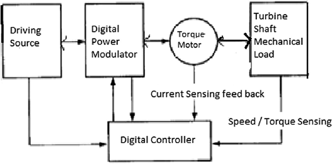
Functional block of torque drive module
Fig. 4 
Typical petrol wheel
Fig. 5 
LPGS functional block diagram
Some of the important parameters and design calculations:
(1). Calculation of water flow rate:
The water flow rate can be calculated by the measuring the river or stream flow velocity and its cross sectional area, then
Q = A × V
A = Area of channel,
V = Velocity of stream
(2) Calculation of Power:
P= ρ* g* Q* Hj ‘ρ’ is the density of fluid and g is the gravity.
d. Calculation of the Turbine Speed (N)
The relation between the specific speed (Ns) and the Net Head is given as
Ns= 85.49×√Nj/Hn.243, Where Nj =No. of jets and N= Ns*Hn5/4/√P
(3). Runner Design:
The mean velocity of the free jet emerging from the nozzle of the turbine is determined from the net head, by the equation
Vj = Cv√2gHn
At the best efficiency point the circumferential speed of the runner is connected with the jet velocity via the relation.
U = (0.46-0.47)*Vj, therefore the Diameter of runner ‘D’ = 60*U/πN
Where N is the speed of runner in rpm.
(4). Nozzle Dia or Jet ‘d’ = √4Q/πVj.
(5). No. of Buckets ‘Z’ = 15 + D/2d
(6). Efficiency of turbine
Torque T= Q*D*( Vj – U), Power transferred by shaft ‘Ps’ = 2π NT/60
Efficiency ɳt = Ps/Pj
-
R.
Types of Electrical Loads: Electrical loads that are normally connected to LPGS system are LED or regular light bulbs, Charge Controllers, TV, exhaust or indoor fans, refrigerators and AC etc. For economical models for communities which supported by Govt. or other agencies the proposed LPGS system can be designed for generating capacities much lower for lesser price compared to the existing systems. Therefore, the system, if required, can be used for charging and store the power. The storage module allows future use of electrical loads especially during the power blackouts and can assure secured energy for emergency devices like Medical gadgets, LED lighting, mobile phone battery charging etc. particularly during the prolonged stormy days when solar energy cannot come at the rescue. Though there are many options available for storage technology [5], here for this LPGS project, keeping the low cost and affordability in mind mainly two types of rechargeable batteries are considered for providing power to small loads which are Lead-Acid and Nickel–Cadmium (Ni-Cad). Based on the power generating capacity, the size of the storage is decided Ni-Cad is preferred for Medical gadgets and mobile applications as it is easier to handle and reliable. Lead-Acid suits for regular domestic loads like LED Bulbs, TV, Fan etc. Contrary to Lead-Acid, Ni-Cad works better and gives prolonged life if it is fully discharged before re-charging. Whereas, the Lead-Acid batteries should never be fully discharged to protect them from permanent damage.


3 Major Issues in the Development of LPGS Power System
There are few concerns in the development of the proposed LPGS system. One is related to civil works, choosing appropriate location, building its own shed for small scale PVC piping system or penstock from the overhead water tank to the turbine, and the second is to deal with specially made guided turbine and clubbing with torque motor along with torque drive controller and the third is Integrating the system modules for better performance as the turbine, TM and PMG all parts determine the functionality and performance of the proposed system.
Design criteria for torque motor module.
The selection of torque motor drive depends on various factors such as:
-
(1)
Steady state governing variables such as speed of the motor verses torque characteristics, speed regulation and control, speed range, efficiency, duty cycle, speed variations, rating etc.)
-
(2)
Operational requirement values like acceleration, deceleration, starting, braking, and speed
-
(3)
reversal etc.
-
(4)
Energy sources requirements: like source types, their capacity, voltage and current magnitude, power factor, harmonics etc.
-
(5)
Capital cost and running cost, maintenance requirements like MTBF etc.
-
(6)
Space limitations and weight constraints.
-
(7)
Neighborhood, environment and location.
-
(8)
Quality, standards, Reliability
4 Conclusion
There are three important things which assure LPGS System to function better as an alternative energy system for electrical power generation intending mainly for small scale utility needs that include domestic usage. These are (1) the pressure of water which is supplied thru the PVC pipe representing the Head (downstream water), (2) the flow rate of water and (3) the torque required to overcome the inertia. This is achieved through a torque motor. This torque motor also ensures consistent required RPM. The first two are often prone to circumstantial change and therefore, it is better to determine both the parameters prior to erection and installation for probable output power estimation. As the friction loss depends on the PVC pipe fitting and other infrastructure, the use of flexible or adjustable nozzle is another solution. Pressure can be varied accordingly to compensate the pressure loss by achieving optimum pressure value. This can be made possible by using an impeller in conjunction with torque motor. And also, the design of guided turbine and the selection of generator in terms of their type, size and capacity are equally important in developing the proposed LPGS System. In the forthcoming paper there will be more details on methods and testing to evaluate the proposed LPGS system performance.
References
European Small Hydropower Association (ESHA): Energy Recovery in Existing Infrastructures with Small Hydropower Plants, Sixth Framework Programme, Publication by Mhylab, Switzerland (2010)
Al-Abedin Syed MA, Naushad Ali MM, Hossain FS, Haque SA, Siddique AH. Prospect of a pico hydro power plant based on irrigation pump in perspective of rural areas in Bangladesh. International Islamic University Chittagong, Bangladesh. The Petroleum Institute, Abu Dhabi, UAE
Indirajith K, Kumar R(2017) Output power calculations: analytical design of axial flux PMG for low speed direct drive wind applications. J Electric Electron Eng
Anyuan C, Nilssen R, Nysveen A (2010) Performance comparisons among radial-flux, multistage axial-flux, and three-phase transverse-flux PM machines for downhole applications. IEEE Trans Ind Appl 46(2):779–789
Mars N, Krouz F, Louar F, Sabita L (2017) Comparison study of different dynamic battery model, Published: 2017 international conference on green energy conversion systems (GECS)
Author information
Authors and Affiliations
Corresponding author
Editor information
Editors and Affiliations
Rights and permissions
Copyright information
© 2022 The Author(s), under exclusive license to Springer Nature Singapore Pte Ltd.
About this paper

Cite this paper
Lolla, S.M., Pulluri, H., Nidamarti, B., Nallanthighal, R.S. (2022). Exploring Alternative Energy Sources to Supplement and Cover the Downtime of Wind and Solar to Improve the Resilience of Smart Grids. In: Pillai, R.K., Ghatikar, G., Sonavane, V.L., Singh, B.P. (eds) ISUW 2020. Lecture Notes in Electrical Engineering, vol 847. Springer, Singapore. https://doi.org/10.1007/978-981-16-9008-2_34
Download citation
DOI: https://doi.org/10.1007/978-981-16-9008-2_34
Published:
Publisher Name: Springer, Singapore
Print ISBN: 978-981-16-9007-5
Online ISBN: 978-981-16-9008-2
eBook Packages: EnergyEnergy (R0)