
Abstract
In recent years, the self-assembly of amphiphiles has been exploited to create nanostructures with controlled architecture and morphology. Maneuvering the intermolecular interactions between organic molecules offers attractive routes to tune the morphology of self-assembled structures. These structures can act as templates or nanoreactors for the creation of different inorganic materials. Amphiphiles have a significant role in regulating the nucleation and growth process of nanomaterials during liquid-phase synthesis. Dynamic equilibrium structures of micelles are employed in fine-tuning the colloidal stability, size distribution, and morphology of a variety of inorganic materials, polymers, etc. The synthesis of inorganic materials in the presence of organic additives offers nanostructured composites with superior properties. Microemulsions are employed as nanoreactors for the synthesis of size-controlled nanoparticles of lipids, polymers, metals, etc. The application of block copolymers in the production and ordering of nanomaterials is gaining increasing attention. Molecular self-assembly has become a key tool in the fabrication of a variety of materials with potential applications in biomaterials development, as carriers for drug delivery and templates for ordered nanostructures. Thus, this chapter focuses on the principles of the self-assembly process, its role in controlling the structure of materials and its applications in the emerging areas of materials development.
Access provided by Autonomous University of Puebla. Download chapter PDF
Keywords
12.1 Introduction
Amphiphiles undergo spontaneous association into longer and meticulous arrangements. In this process, molecular building blocks organize into a well-ordered structure, by virtue of specific mutual interactions [1, 2]. Self-assembly processes, related to amphiphilic molecules, offer a unique platform for developing new nanomaterials for advanced scientific applications [3]. Nature created the maturation of biomolecules from the primordial by self-assembly and eventually shaped a colossal amount of complex biological systems. In biological systems, self-assembly is omnipresent and the assembled structures have their exclusive cellular functions. Thus, the self-assembly processes of amphiphiles have drawn significant interest for the past few decades due to their explicit biological system mimicking competence such as assembly of proteins and lipids apace with comprehensive utilization in biological applications. Contemporary advancements in the area of nanotechnology accelerated the amalgamation of elementary processes of self-association with the progressive concept for the design of hierarchical nanostructures. Inauguration of stimuli-responsive amphiphilic assembly–disassembly mechanism grants new methods for producing diverse bionanotechnology applications. Hence, studying amphiphilic self-assembly is imperative to the present effort of nanotechnology as this process caters to the direction of creating molecular building blocks [4,5,6,7].
12.2 Self-Assembly of Amphiphiles
Amphiphiles are natural or synthesized molecules that contain two distinct parts; namely, a hydrophilic part (water-loving, polar) designated as “head” group and a hydrophobic part (fat-loving, ‘tail” group), which are able to aggregate into various nanostructures [8]. In conventional amphiphiles, the fat-loving tail often consists of a long hydrocarbon chain (either saturated or unsaturated), whereas the water-loving head can be ionic (cationic/anionic) or nonionic in nature. Typical hydrophilic head groups of the nonionic surfactants are polyhydroxyl or polyether units. Unlike ionic surfactants, these surfactants do not dissociate upon dissolving in an aqueous medium and possess a wide range of properties based on the ratio of hydrophilic-lipophilic balance (HLB). The most common nonionic surfactants are polyglycerol alkyl ethers, ester-linked molecules, Spans (sorbitan esters), Brij and Tweens, etc. Cationic surfactants are composed of a positively charged headgroup and a halide counterpart. Cetyltrimethylammonium bromide (CTAB) and dodecyltrimethylammonium bromide (DTAB) are widely used cationic amphiphiles. Anionic surfactants generally consist of negatively charged headgroups (carboxylate, sulfate, sulfonate and phosphate) and positively charged counterparts (Na+, K+ or NH4+ ions). Sodium bis(2-ethylhexyl) sulfosuccinate, with the trade name Aerosol-OT (AOT) and sodium dodecyl sulfate (SDS) are common examples of anionic surfactant. In zwitterionic amphiphiles such as phospholipid phosphatidylcholine, the headgroups have both positive and negative charge moieties. The chemical structures of some surfactants are shown in Fig. 12.1.

Structures of a few common surfactants under different categories
When dissolved in water, the polar head group of the surfactant interacts with the water, whereas the nonpolar tail migrates toward the interface (either toward air or nonpolar liquid). Thus, the interruption of cohesive energy at the interface helps the formation of micelles, vesicles, lamellae, etc. Micelles are equilibrium assemblies of amphiphile/ surfactant molecules dispersed in a liquid medium. Micelles are formed when the concentration of amphiphile reaches above a threshold value known as the critical micelle concentration (CMC). In a normal micelle, polar or ionic heads create an outer shell in association with water, whereas nonpolar hydrophobic tails are seized in the interior. The amphiphilic molecules can also form micelles in nonpolar organic mediums. These micelle aggregates are termed as inverse or reverse micelles. In inverse (reverse) micelles, the polar head groups are situated at the core, while the tails extend outwards to the solvent medium. In addition to micelles, amphiphiles help in the formation of microemulsions which are clear and thermodynamically stable liquid dispersions containing water, oil and surfactant. Often, in microemulsions, the aggregates are much larger in size. There are mainly three varieties of microemulsions such as direct (oil dispersed in water, o/w), reversed (water dispersed in oil, w/o), and bicontinuous. They have large liquid cores surrounded by a surfactant monolayer which stabilizes the dispersion. The microemulsion domains are typically studied by making ternary-phase diagrams mainly consisting of two immiscible liquids and a surfactant. Most of the microemulsions use water and oil as two immiscible liquids. The shape of micelles is mainly spherical. However, other shapes like bilayers, ellipsoids, and cylinders also exist. In a few cases, micelles can grow very long and entangle like long-chain polymer. The amphiphiles do not always associate with micelles and in some cases, they associate into extended flat lamellae without forming a closed structure (so-called lamellar structure). Closed bilayer structures are known as vesicles which encircle an aqueous pool and are surrounded by an aqueous solution. It composes of a bilayer of amphipathic molecules, in which the hydrophilic heads of the outer layer are exposed to the outer side, whereas the hydrophilic heads of the inner layer make the inner hydrophilic core. The hydrophobic tails are situated in between the bilayers of two concentric circles. The schematic representation of micelles, vesicles, and lamellae is shown in Fig. 12.2. The formation of these self-assembled structures based on critical packing parameters is discussed in the following section.

Schematic representation of different structures formed by amphiphiles
12.2.1 Morphological Control of Self-Assembled Structures
12.2.1.1 Surfactant Assemblies
The self-association of amphiphilic molecules results in a large variety of structures such as spherical micelles, anisotropic micelles, bilayers, vesicles, liposomes, microemulsions, liquid crystalline dispersions, etc. The morphology of these aggregates is governed by the interaction of hydrophilic and hydrophobic forces responsible for the self-assembly process [9, 10]. The hydrophobic effect due to the hydrocarbon tails favors the self-assembly process. On the other hand, the solvation of the hydrophilic head group restricts the packing of amphiphilic molecules and hence opposes the self-assembly. The electrostatic repulsion between the head groups of ionic surfactants also contributes toward limiting the growth of self-assembled structure. In general, the stability of association structures in solution depends on the hydration of the polar head groups and insertion of the nonpolar tail in the solvent. The amphiphile self-assemble into various supramolecular structures mainly due to the combined effect of various noncovalent interactions such as solvation, hydrogen bonding, hydrophobic effect, etc. The other important interparticle interaction involved in amphiphile self-assembly, specifically with ionic amphiphiles self-assembly is denoted by the Derjaguin, Landau, Vervey, and Overbeek (DLVO) theory [11]. This theory is the key foundation to rationalize the interfacial forces acted among charged amphiphiles and explain their agglomeration behavior in solution [12]. Further, the geometry (size and shape) of self-assembled structures depends on various additional factors like surfactant concentration, nature of surfactant, ionic strength of the medium, nature of the counterion, temperature, pH and nature of the additives, etc. The prediction of the geometry of a self-assembled structure in a surfactant-water system was a subject of major interest in the past. Consequently, some models have been proposed, which are helpful in predicting the shape of self-assembled structures in the surfactant-water system. The morphology of self-assemblies is satisfactorily explained by the geometric packing models [13, 14]. According to this model, the three main factors that dictate the geometry of a surfactant aggregate are length (l) and the volume (v) of the hydrophobic chain and the effective interfacial (head group) area (ao) of the surfactant molecule. For a hydrocarbon chain, the length (l) and volume (v) of the surfactant tail can be found by the Tanford formulae using the following equations:
“n” represents is the number of carbon atoms in the linear alkyl chain.
The head group area of the surfactant molecule can be obtained from surface tension (γ) data using Gibbs adsorption isotherm. Surfactants are amphiphilic in nature and in their presence, the surface tension of water decreases due to the adsorption of molecules at the surface. A steady reduction in γ followed by a linear decrease can be seen in the plot of γ versus log C (concentration of surfactant). Once CMC is attained, no change in γ occurs. From the slope of the linear portion of γ versus -logC plot, the surface excess concentration Γ (number of moles of surfactants per unit area (m2) at the interface) can be determined using Gibb’s equation.
According to the Gibbs relationship, at constant temperature, the surface tension γ and the surface excess (Γ) for a single surfactant component can be simply expressed as follows:
where C, R, and T represent the surfactant concentration, gas constant, and absolute temperature, respectively.
The area per molecule can be obtained from Γ, by using the relation,
where NA is Avogadro's number. For ionic surfactants having carboxylate, sulfate, headgroups, etc., the area per surfactant is usually in the range of 0.4 nm2, while for nonionic surfactants it is much higher (1–2 nm2). Israelachivili and coworkers [14] suggested that the geometry of aggregated structures formed in the solution is a resultant of the optimum packing of molecules into aggregates. The optimum packing of surfactants into a surfactant assembly can be defined by a dimensionless parameter known as the critical packing parameter. The critical packing parameter (N) depends on the length (l) and volume (v) of the hydrophobic part, and the effective head group area (ao) of the surfactant molecule.
The packing parameter for different geometries of aggregates is different as per simple geometric calculations. For instance, the volume and surface area of a spherical micelle of radius, R and aggregation number, N can be expressed as
Here v and ao are the volume and headgroup area of the single surfactant molecule.
Since the maximum radius of a spherical micelle can be the length of the hydrocarbon part, l. by rearranging the Eqs. 12.5 and 12.6, we get
or in in the form of packing parameter, we can write it as
Therefore, if the value of N is less than 1/3, the aggregates will preferably result in spherical geometry. In a similar manner, if the packing parameter is calculated for cylindrical geometry, N will be between 1/3 and 1/2, while for curved bilayer or vesicles, it is 1/2. For flat bilayers, the packing parameter approaches 1, whereas, for reverse micelles, the value of N is > 1.
In the case of vesicles, bilayers etc., there is another factor known as curvature energy, which is very crucial in controlling the geometry of the aggregates. As per the model of Helfrich [15], the free energy (F) per unit area (A) of a bilayer is related to the bilayer curvature by the equation
where c1 and c2 represent two principal curvatures of the bilayer and cs represents spontaneous curvature. The rigidity of the bilayer is related to \(\kappa _{s}\), the bending modulus which is of the order of \({\text{k}}\beta {\text{T}}\), where \({\text{k}}\beta\) is Boltzmann constant. The different aggregate structure which can be anticipated from the packing parameter is shown in Fig. 12.3.

Different aggregate structures which can be predicted from critical packing factor
It is worth mentioning that the packing considerations of the surfactant molecule are built in the spontaneous curvature of the bilayers. For instance, if the interaction between the polar head groups of the surfactant results in a smaller packing area as compared to the hydrophobic tail interactions, the surfactant monolayer will tend to curve in such a way that the polar headgroups are on the inner side of the monolayer. On the other hand, if the interaction between the headgroups leads to the larger packing in comparison to the tail–tail interaction, the polar headgroups arrange themselves on the outer side of the monolayer.
12.2.1.2 Block Copolymer
The concept of amphiphile can be extended to macromolecular polymer-based amphiphiles by linking hydrophilic/hydrophobic polymer blocks. Block copolymers are mainly macromolecular compounds having two or more chemically dissimilar blocks conjugated to each other by covalent bonds. These materials exhibit amphiphilic character when the two blocks show different polarities [16]. The investigation of self-assembly characteristics of these compounds is an interesting research area to explore due to their rich structural polymorphism and different applications such as lithography for microelectronics, photovoltaics, drug delivery, nanostructure formation, etc. [16,17,18,19]. Further, block copolymer self-assembly can produce well-ordered structures of different morphologies such as spheres, cylinders, lamellae, vesicles, bicontinuous structures, and many other complexes or hierarchical assemblies [20]. Depending on the absolute and relative block lengths, the nature and architecture of the blocks, these copolymers form a diverse set of nanostructures that range from discrete micelles to vesicles to even gel-forming continuous network structures [16]. Recent progress in the synthesis route facilitate the preparation of block copolymers with desired molecular weights, compositions and architectures [16]. Like conventional surfactants, the self-assembly of these compounds in an aqueous medium is entropy driven arising out of gain in entropy due to destruction of water structures around the hydrophobic blocks [16].
Figure 12.4 shows a typical phase diagram of a block copolymer–water two-component system. At low and very high block copolymer concentrations normal and reverse micelles are formed. Liquid crystalline structures with different microstructures are formed at copolymer concentrations in between these two extremes [21]. Micelles formed are usually core–shell types with the core comprising hydrophobic blocks and the corona comprising the hydrophilic blocks.

Typical phase diagram of a block copolymer–water two-component system
Self-assembly behavior of many of these block copolymers is strongly dependent on temperature because of the differential solubility of the different blocks [22]. The solubility of the blocks in general decreases with an increase in temperature and they show phase separation at characteristic temperatures called cloud points [22]. Besides, micellar structural changes from spherical to rod-like or to disk-like shapes or to layered vesicle-like structures are also observed on approaching the phase separation temperatures [23]. These are attributed to changing critical packing parameters of the self-assembled structures as a function of temperature. Some of the block copolymers also exhibit critical behavior because of the onset of micellar attractive interaction and resulting micellar cluster formation on the verge of phase separation [24].
Self-assembly characteristics of block copolymers in water are also sensitive to the presence of additives that modulate the solubility characteristics of the blocks. Water structure making salts, hydrophobic solvents and solvents like glycerol increases the hydrophobicity of the copolymers and promotes the formation of aggregates [25]. Water structure breaking salts and solvents like ethanol, on the other hand, have disrupting influence on the self-assembled structure formation [25]. Triblock copolymers like Pluronics form a rich set of self-assembled structures in water-block copolymer–oil three-component systems [21].
12.2.2 Kinetics of Micellization of Amphiphiles
The primary requirement for the formation of self-assembly of amphiphile is the lowest free energy state at equilibrium. Generally, the self-assembly of the structure of amphiphile has lower entropy than the individual counterparts. Thus, the self-assembly of amphiphilic molecules is governed by the interfacial energy of the micellar core with solvent and the conformational distortion energy of the soluble chains and the favorable increase in entropy of the solvent molecules. Micelles are generally considered as spherically aggregated inert structures of amphiphile molecules. However, they are in dynamic equilibrium with individual amphiphile which is continuously replaced among bulk and micelles. Further, the micelles themselves undergo dissolution and reforming. Therefore, there are two relaxation processes occurred in micelle solutions [26]. The fast relaxation process of relaxation time, τ1 (order of microseconds) is related to the exchange of amphiphile monomers among micelles and the surrounding bulk phase through the collision process. The second slow relaxation time, τ2 (in the order of milliseconds to minutes) is associated with the process of complete disruption of micelles. The micellar relaxation kinetics are dependent on the concentration of micelle, temperature, and pressure of the micellar solution. A schematic illustration of the two relaxation times, τ1 and τ2 related to micelle formation is shown in Fig. 12.5.

Schematic illustration of the two relaxation times, τ1 and τ2 for an amphiphile solution above CMC (reproduced with permission A. Patist et al., Colloids Surf. A: Physicochem. Eng. Asp. 176 (2001) 3–16, Copyright © 2001 Elsevier Science B. V. [26]
Hadgiivanova et al. [27] demonstrated a new free-energy-based theoretical approximation to the kinetics of amphiphile micellization, where the different stages of aggregation are considered as constrained path ways on a single free energy landscape. They have identified three stages of micelle formation such as nucleation, growth, and relaxation steps of well-separated time. The first stage is involved with homogeneous nucleation of micelles, which are dependent on the concentration of surfactant, rate of nucleation, and critical size of nuclei. The first stage is much longer than the other two as it is an activated process. The growth stage is diffusion limited for the concentration of surfactant slightly higher than CMC and it is either diffusion limited or kinetically limited for higher concentrations. Depending on the surfactant concentration, the micelle size may be either bigger or smaller than its equilibrium size at the end of the growth stage. In the relaxation stage, micelles relax to the equilibrium size by fission (a decrease in aggregate size) or fusion (an enhancement in aggregate concentration) process.
Kinetics of formation of block copolymer self-assembled aggregates is slower by a few orders of magnitude than that of ionic surfactants owing to their higher molecular mass [28]. Many of the aqueous block copolymer systems thus exhibit time-dependent micellar structural changes and even leads to the formation of kinetically arrested metastable systems [29, 30]. Quite expectedly such tendencies increase with an increase in hydrophobicity and molecular weight of the copolymers making their kinetics of aggregate formation increasingly sluggish.
12.3 Principle of Nanomaterials Synthesis
The nanostructured materials deal with the property-decisive phenomenon that happens in typically the size range of 1–100 nm. The most important part to be focused on is to what the accord between their structures and compositions is, and how their interface supervises the property of the material as a whole [31]. Mainly two different types of methods are often used for producing nanostructures. The first one is the bottom-up method where the material is manufactured from atomic or molecular species through chemical reactions, which enables the particles to grow in size to produce nano-sized structures. These nanostructures can sometimes form in parallel and be nearly identical, with no long-range order. [32, 33]. An opposite approach is to break a bulk material into smaller pieces using chemical, mechanical or other forms of energy, called the top-down method [34]. In this, lithographic techniques are used to design materials. Materials science desires a handy policy to link these two approaches and to permit the production of materials with a satisfactory resolution [35, 36]. There are many instances of self-assembly connecting top-down and bottom-up constructions [37]. However, bottom-up self-assembly is surprisingly beneficial because it grants the accumulation of structures too small to be manipulated independently into the ordered arrangements or patterns. Researchers have developed varieties of soft-chemical approaches based on bottom-up self-assembly to formulate nanoparticles of well-defined composition, shape, and size. These soft-chemical approaches for the preparation of nanomaterials include the coprecipitation method, sol–gel process, hydrothermal synthesis, high-temperature reactions, microwave irradiation synthesis and polyol method, sonochemical synthesis, microemulsion, etc. [38,39,40]. In all these synthesis methodologies, the formation of nanoparticles undergoes two important processes, namely nucleation and growth.
12.3.1 Nucleation
In soft-chemical approaches, the nucleation process kicks off the evolution of a new phase from a solution. The atoms or molecules of the reactants reshuffle into a cluster of products, which has the ability to grow irreversibly to a macroscopically bigger size. The cluster or group is entitled as a nucleus or critical nuclei [41]. When nucleation occurs without the presence of foreign particles or crystals in the solution, it is termed as homogeneous nucleation. On the other hand, if the nucleation is induced by the existence of any foreign particles in the solution, it is termed as heterogeneous nucleation. These two together are termed as primary nucleation. In contrary to primary nucleation, secondary nucleation comes into the picture when crystals of the same substance induce nucleation.
The main driving force behind nucleation and subsequent growth of a crystal is supersaturation. This depends on the chemical potential of a molecule in solution (µs) and that in the bulk of the crystal phase (µc) as follows:
Thus, using thermodynamics we can write from Eq. (12.12):
where T is the absolute temperature, k is the Boltzmann constant and S is the supersaturation ratio [42]. The solution is termed as supersaturated, when \(\Delta \mu > 0\), thereby confirming the possibility of nucleation and/or growth, whereas \(\Delta \mu < 0\) suggests that the solution is under saturated and dissolution will take place. Now, this supersaturation ratio can have different forms based on the system under consideration. The mathematical expression for the degree of supersaturation is given below:
where ni is the number of ith ions in the molecule of the crystal, and ai and ai,e are the activities of the ith species in supersaturated solution and in equilibrium state, respectively.
Now, let us look at the thermodynamics of homogeneous nuclei formation. Figure 12.6 shows the (a) free energy diagram for nucleation explaining the existence of a “critical nucleus” and (b) a representative plot of nucleation rate, J as a function of supersaturation, S showing critical supersaturation. The total free energy of nanoparticles is the summation of the bulk free energy (ΔGv) and surface free energy (ΔGS), as shown in Fig. 12.6a [43]. Thus, for a spherical particle with surface energy γ, radius r, and the free energy of the bulk crystal Gv, the total free energy ΔG is given by Eq. 12.5. The bulk free energy (ΔGv) depends on the degree of supersaturation and is given by Eq. 12.16, where kβ is Boltzmann’s constant, S is the supersaturation ratio and V is its molar volume.
The surface free energy and crystal free energy are always positive and negative, respectively. Thus, a maximum free energy can be found which a nucleus will surpass to produce a stable nucleus. This critical value of radius can be obtained by equating the first derivative of ΔG with respect to r equal to zero. The critical radius which indicates the minimum size at which a particle can form in the solution without getting dissolved is given in Eq. 12.18. It is evident from the equation that the possibility of nucleation in a given system increases with the increase in supersaturation as critical radius decrease [44].
The rate of nucleation, J which is defined as the number of nuclei formed per unit time per unit volume is expressed by an Arrhenius-type equation (Eq. 12.19) with the activation barrier equal to ΔGcrit:
From a representative plot of J as a function of S (Fig. 12.6b), we can clearly see that up to a certain value of supersaturation, nucleation rate is essentially zero and then it starts increasing exponentially from there. This critical supersaturation (Δμc) point describes the allegedly metastable zone showing crystal growth can advance without having collateral nucleation.

a Schematic representation of the free energy diagram for nucleation explaining the existence of a “critical nucleus” and b a representative plot of nucleation rate, J as a function of supersaturation, S showing critical supersaturation
Equation 12.17 and 12.18 have shown us that the \(\Delta G_{crit}\) and \(r_{crit}\) both are highly dependent on the surface free energy parameter, i.e., \(\gamma\). Thus, any change in this parameter will have a certain effect on the nucleation process. Presence of foreign substances decreases the value of \(\Delta G_{crit}\) and \(r_{crit}\) at constant supersaturation and making nucleation more favorable [45]. Decrease in \(\gamma\) also declines the value of critical supersaturation, thus making the heterogeneous nucleation much more feasible than homogeneous nucleation at low supersaturated states. Now, this reduction in surface free energy is maximum when the foreign substance and the crystallizing substance are identical which leads to secondary nucleation.
12.3.2 Growth
Crystal growth is another intricate process where an atom or molecule is deposited over the surface of the crystal, which leads to the increase of size. This growth process can either be reaction limited or diffusion limited. Most of the cases have shown to be diffusion controlled only where temperature and concentration gradient has played a major role in defining the rate of growth as the new material is added to the surface of the particle [46]. There are various theories of nucleation and growth of nanoparticles available in the literature. We will be discussing a few here to get an overall idea about the same.
-
(a)
LaMer mechanism
The inaugural idea of nucleation and growth was given by LaMer [47] where he separated the nucleation and growth into two different stages (Fig. 12.7). He investigated the preparation of sulfur sols from the decomposition of sodium thiosulphate and proposed two distinct steps where nucleation is the formation of free sulfur from thiosulphate and growth is the formation of sulfur sols. The full process is further fractioned into three parts. (A) at first, the concentration of the free monomer is raised in solution, (B) the second part is the “burst nucleation” that reduces the free monomer concentration and at this point, nucleation is almost arrested due to very low monomer concentration, (C) the third portion is diffusion mediated growth in the solution. Changes in the reactant concentration during all three stages are depicted in Fig. 12.7 [48, 49].
Fig. 12.7 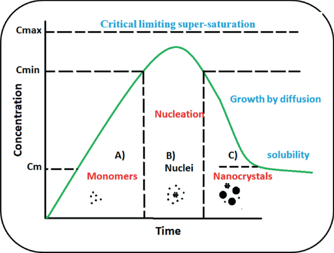
Schematic illustration of the changes in reactant concentration as per LaMer mechanism of nucleation and growth
-
(b)
Ostwald ripening
In 1900 another theory was published to describe the growth phenomenon of crystal in solution which was termed as Ostwald ripening [50]. In his theory, he described the crystal growth where smaller particles are being consumed by larger particles and the main cause behind this is the solubility of nanoparticles in size-dependent manner. Greater solubility and the surface energy of smaller nanoparticles in solution enforce them to redissolve and grow larger ones even larger. A detailed mathematical explanation of Ostwald ripening is described by different research groups [51, 52]. Digestive ripening is basically just the opposite of Ostwald ripening where larger particles redissolve and smaller particles grow [53].
-
(c)
Finke–Watzky mechanism
Another mechanism was proposed for describing nucleation and growth of nanoparticles which is called as the Finke–Watzky two-step mechanism. In this nonclassical process, nucleation and growth both occur simultaneously [54]. This model fits well in various systems including the synthesis of iridium, platinum, ruthenium, and rhodium [55,56,57].

12.3.3 Role of Surfactants in Nanomaterials Synthesis
Irrespective of the synthesis approach, the preparation of nanomaterials always comprises nucleation and growth processes. The separation between them is tremendously difficult in the aqueous-based chemical synthesis approaches. The polydispersity of nanoparticles is remarkably decreased when nucleation and growth steps are well separated, which is extremely difficult to achieve. As far as thermodynamics is concerned, without any stabilizer the agglomeration of smaller particles in solution is inevitable. This agglomeration can take place at any stage of synthesis and thus making it a subject of investigation. Mainly two kinds of stabilization can be imparted to nanoparticles. First, electrostatic stabilization by means of repulsion between charged species at the surface and secondly, steric stabilization by virtue of surface fictionalization or capping the surface by long-chain moieties such as surfactants and polymers [58]. The second one is quite common and mostly followed due to its easy fabrication and chemical stability in a wide pH range [59].
Various surfactant molecules are used for the stabilization of nanoparticles in solution and the prevention of nanoparticles aggregation in solution by forming robust coating around the particles during synthesis or post-synthesis process. In addition to this, surfactant amphiphiles are also used as templates or nanoreactors for the synthesis of different shaped controlled nanoparticles [60]. The tuning of the nucleation process with the assistance of surfactant amphiphiles has a significant degree of control over the size distribution of the synthesized nanoparticles. Therefore, nanoparticles synthesis by surfactant self-assembly has been extensively used due to its superior ability in controlling the structural morphology and size of nanoparticles [61,62,63]. Specifically, nanoparticles–amphiphiles soft interactions are accountable for nanoparticles functionalization, colloidal and chemical stability procedures.
12.4 Self-Assemblies as a Template for Nanomaterials Synthesis
12.4.1 Surfactant Assisted Synthesis
Self-assembly process is ubiquitous in nature. There are several examples in living organisms, where the self-assembly process fabricates unique structures. For example, in bones, teeth, spines, shells, etc., the biomineralization takes place through a self-assembly process on a protein scaffold. In these structures, the organic template and inorganic minerals interact at molecular level and results in the structures with remarkable properties in spite of having very soft templates and brittle minerals as the constituting elements. The use of synthetic templates, inspired by nature is evolving as one of the promising routes for the fabrication of novel materials with controlled architecture inspired by nature. Recently, there is a growing interest in the preparation of hollow inorganic nanomaterials having well-defined geometrical features because of their characteristic properties such as controlled geometry and pore size, low density, huge specific area, and high mechanical and thermal stability. Owing to their fascinating properties, these hollow nanomaterials have tremendous potential for diverse technological applications ranging from everyday materials and processes, medical and health care, energy applications, electronics, and information technology applications to environmental remediation. A number of materials have been involved in pharmaceutical formulations, cosmetics, paint industry, catalysis, as well as for dyes and ink. The geometrical parameters of nanostructures including size, shape, composition, architecture, and surface area are some of the most important parameters to define various important properties of inorganic nanomaterials. Hence a lot of efforts have been made to exploit the fabrication of well-defined inorganic nanostructures using various methods involving physical as well as chemical routes. The involvement of sacrificial templates such as polymeric nanoparticles, self-assembled structures, etc., in the fabrication of nanomaterials with controlled size, morphology, and surface properties have also emerged as a growing field.
The self-assembly templating method has revolutionized the fabrication of smaller well-defined hollow nanomaterials having diameters in the nanometer range. Self-assemblies of amphiphilic molecules are one of the most promising templates to synthesize nanomaterials having defined architecture and high surface area. As discussed above, the self-association of amphiphilic molecules such as ionic/nonionic surfactants results in different structures and the morphology of these self-assembled structures is decided by a number of factors including, surfactant concentration, temperature, and nature of surfactant molecule as well as additives, if any. Self-assembled structures are dynamic in nature and are very receptive to the changes made in the constituting solutions. Hence, their microstructure and properties can be tuned easily by changing the concentration of surfactant, addition of inorganic electrolytes or organic additives as well as by varying the pH and temperature of the medium. For example, in the case of ionic micelles, the addition of inorganic electrolytes decreases intermicellar repulsion as it screens the charge at the micelle surface. This changes the packing parameter, which in turn changes the morphology of the aggregates. Organic hydrotropes (hydrotropes are used to solubilize hydrophobic compounds in water medium by means other than micellar solubilization) are very effective in inducing the morphological changes in ionic aggregates by decreasing the surface charge at the micellar surface. The swelling of the micelles also takes place due to the solubilization of organic additives in the hydrophobic cores of the aggregates. Similarly, the change in the temperature of the solution results in the alteration of the head group area of the ionic and nonionic surfactants. As a consequence, the packing parameter of the surfactant changes and results in a change in the size and shape of the aggregates [64,65,66,67,68,69]. Hence, one of the major advantages of using self-assemblies as templates is that the morphology and porosity of the materials can be tuned to the desired extent by tuning the parameters affecting the microstructure of self-assemblies. Amphiphilic block copolymers have also been broadly employed for designing hollow nanostructures and ordered mesoporous materials. The polymeric micelles have a core composed of a hydrophobic block of copolymers and corona made up of the hydrophilic group of copolymers. The core of the micelles acts as a template of the hollow nanostructures and corona acts as a reservoir of the inorganic precursors [70].
The synthesis of inorganic materials, such as silica, titania, alumina, hydroxyapatite, metal oxide, metal phosphate, etc., using self-assembled structures as a template, has been a topic of tremendous importance [71]. There are several reports in which the employment of self-assembly during synthesis has resulted in materials with controlled geometry, and defined porous structure and are found to be very promising for diverse applications. MCM-41, belonging to the family of silicates is a well-known porous material with very high surface areas of the order of 1000 m2/g with a pore size ranging from 2 to 20 nm and ordered arrays of cylindrical mesopores with very regular pore morphology [72]. During the synthesis of MCM-41, the hexagonal arrays of rod-like micelles of cationic surfactant, cetyltrimethylammonium bromide are employed as a template. The synthesis of material takes place at the surface of the templates and during calcination, the organic template is removed leaving a highly ordered porous material. Due to the large surface area of these materials, the possibility of reactant molecules reacting with the catalyst surface increases. These materials are widely used for catalytic applications. Since, the discovery of mesoporous molecular sieves by Kuroda et al., known as KSW-1 [73] and FSM-16, [74] and by Exxon Mobil, called M41S [72] a great deal of attention has been given to the investigation of mesoporous silica materials due to their wide range of applications. Recently, hollow silica spheres (HSS) with significant inner spaces, high specific surface area, mesoporous structure, and amorphous shell were synthesized using cetyltrimethylammonium bromide micelles as a soft template. The composite membrane prepared by mixing HSS with waterborne polyurethane showed improved water vapor permeability, water resistance, and mechanical performance [75]. In another study, hollow silica nanospheres with a highly uniform size were prepared using a micellar template with a core–shell-corona architecture composed of a triblock copolymer, poly (styrene-b-2-vinyl pyridine-b-ethylene oxide). The empty space in the hollow particle could be regulated by the size of the core regulated by the chain length of the polystyrene block, while the shell thickness of nanospheres could be tuned by altering the concentration of the inorganic precursors [76].
Porous hydroxyapatite has attracted increasing interest because of its biocompatibility, bioactivity, osteointegration, osteoconductivity, and composition similarity with human bones and teeth. Hydroxyapatite is an inorganic material belonging to the apatite group, which is comprised of calcium, phosphate, and hydroxide. The chemical formula of hydroxyapatite is Ca5(PO4)3(OH), which is commonly written as Ca10(PO4)6(OH)2 suggesting the presence of two entities in the crystal unit cell. Bone is a hybrid structure comprised of inorganic needle-shaped carbonated and calcium-deficient hydroxyapatite nanocrystals and the organic part is mainly composed of the collagen matrix. The collagen matrix controls the nanoscale structure of hydroxyapatite and dictates its properties. Inspired by biomineralization, a great deal of attention has been paid by the chemists to the biomimetic synthesis of hydroxyapatite having controlled dimensional, morphological, and architectural features by using nanostructured self-assemblies as templates. The involvement of synthetic polymers and surfactant assemblies similar to that of collagen matrix during synthesis of hydroxyapatite could mimic biomineralization and leads to materials with characteristic morphology and porosity. Due to its excellent properties, synthetic hydroxyapatite has been extensively used in a range of biomedical applications including repairing and regeneration of damaged bones, as a filler for bone defects, and to replace amputated bones and as a bone graft. Hydroxyapatite has also been applied as a coating material to prosthetic implants in order to provide biocompatibility and bioactivity to implants.
The morphology and porosity of hydroxyapatite play an important role in making it a suitable material for biomedical applications. The presence of pores in hydroxyapatite supports the in-growth of bone tissue and full assimilation with the bones. Recently, porous hydroxyapatite is also being considered as a potential carrier for various molecules such as drugs, osteogenic agents, etc., which are used in treating bone infection, diseases, etc. There are several reports, which show the preparation of hydroxyapatite with controllable properties and porous structure using self-assemblies as templates. Stupp and coworkers employed ordered nanofibrous self-assemblies of peptide amphiphiles [77, 78] as nucleating centers for the mineralization of hydroxyapatite. They have also synthesized apatite-based materials using homopolymer poly(amino acids) and synthetic polyelectrolytes [79]. Self-assemblies of surfactants, as well as block copolymers, have been found very promising in dictating the geometry and porosity of hydroxyapatite. The usage of spherical micelles of cationic surfactant cetrimide as a template during synthesis resulted in spherical particles of hydroxyapatite, while in the presence of rod-like micelles of cetyltrimethylammonium bromide, the hydroxyapatite nanoparticles formed were rod-shaped [80,81,82]. Similarly, well-aligned hydroxyapatite nanorods were formed due to the templating by hexagonal liquid crystalline phase of a nonionic surfactant, Triton X-100, [83]. Several groups have also prepared hydroxyapatite nanostructures using self-assemblies as a template for drug delivery applications. Calcium-deficient hydroxyapatite hollow nanorods having mesopores on their surface were prepared using P123 and tween-60 as templates. The nanorods showed enhanced protein load and sustained release behavior with a cumulative release of 84.2% over a period of 72 h [84]. In another study, hydroxyapatite hollow nanoparticles (HA HNPs) prepared using core–shell micelles composed of pluronic P123 and Tween-60 showed much higher drug loading for vancomycin drug as compared to nanoparticles prepared in the absence of micelles. In the presence of citric acid used as a cosurfactant, the morphology of the HA HNPs changed from nanospheres to nanotubes and the drug loading efficiency improved further due to the presence of a layer of citrate molecules on the hydroxyapatite surface [85]. An anticancer drug paclitaxel loaded in hydroxyapatite-collagen composites showed enhanced toxicity toward highly metastatic MDA-MB-231 cells in comparison to that of poorly metastatic MCF-7 cells through in-vitro studies. However, the collagen-containing free paclitaxel in the absence of hydroxyapatite was nontoxic toward both the cancer cells suggesting that hydroxyapatite-collagen composite could be employed as a promising drug carrier for paclitaxel [86]. The textural properties of hollow mesoporous carbonated HAp microsphere (CHAM) fabricated using sodium dodecyl sulfate (SDS) mediated precipitation can be controlled by changing the concentration of SDS. The CHAMs showed excellent biodegradability, high loading efficiency for cis-diammineplatinum (II) dichloride and a pH-dependent sustained release of drug. In vitro studies showed that drug-loaded CHAMs have high toxicity toward human squamous cell carcinoma [87].
Mesoporous “transition metal oxides” in particular, titania (TiO2) have also drawn the attention due to the their intrinsic optical and electronic properties. The mesoporous titania shows extraordinary performance in applications such as photocatalysis and optical devices, which has made it to play a substantial role in solar-energy-based photovoltaic devices. Similarly, the high surface area, larger pore volume, and ordered pore structure of mesoporous TiO2 make them desirable for various applications. For example, mesoporous TiO2 (anatase phase) is highly desirable in photovoltaic applications as the photoanodes as high surface area mesoporous TiO2 maximizes the dye-loading capacity and results in high photovoltaic efficiency [87]. There are several reports presenting the surfactant template-assisted synthesis of mesoporous TiO2 [88]. Several liquid-crystalline phases of ionic/nonionic surfactants are being employed as a template during the synthesis of mesoporous TiO2 [89].
12.4.2 Block Copolymer Mediated Nanomaterial Synthesis
Numerous nano-sized self-assembled structures that are formed by block copolymers are good templating agents for generating nanostructured materials with desired and tunable structural properties. Various types of nanostructures formed by using these materials as templates are discussed here. Of late, block copolymer micellar systems are the preferred choice over those of classical surfactants for use as nanocontainers to form metal nanoparticles because of their better kinetic stability and a more robust core-corona structure, which provide better stability to the nano particles against Ostwald ripening [16, 90, 91]. By incorporating coordination properties in the constituting blocks, we can also induce selectivity in nano particle formation [16, 90, 91]. When physically adsorbed on metal nanoparticles, these block copolymers can stabilize them and in addition, can facilitate their integration into different systems where hydrophobic surface poses a problem [92]. Some block copolymers act as reductants thus avoiding the use of environmentally hazardous reagents and the material properties can be tuned by simply changing the composition of the block copolymers [93]. The presence of block copolymers like Pluronic F127 helps in promoting the formation of nanonetwork and dendritic metal structures with tunable surface properties [94]. In these cases, the copolymer used at a concentration below its CMC indicating that the formation and growth of metal nanostructure occurred along the unaggregated free copolymer chains. Finally, metal nanoparticles formed and dispersed in block copolymer three-dimensional liquid crystalline structures can make nanocomposite materials with suitable mechanical, optical, and electrical properties [95, 96].
According to IUPAC notation, a mesoporous material consists of pores with diameters in the range of 2–50 nm. Apart from silica, which is the most commonly used material for this, other materials like alumina, carbon niobium, tantalum, titanium, zirconium, cerium, and tin too reported to form mesoporous structure [97, 98]. Mesoporous materials have tremendous applications in drug delivery, catalysis, biosensing, ion exchange, optics, and photovoltaics. Block copolymers are widely used to form mesoporous oxides because of their nontoxic and biodegradable nature.
Traditionally, top-down lithographic techniques were used to form structural patterns at nanoscale. These methods are expensive and are inherently slow in pattern writing. Bottom-up self-assembly processes involving block copolymers are thus being considered as a suitable alternative to these traditional methods. Selective etching of one block from the self-assembled structures formed in block copolymer films can be used to form templates for making nanopatterns of magnetic and metal nanoparticles for application in photovoltaics, biosensing, etc. [99].
12.5 Microemulsions as Nanoreactors for Synthesis of Nanomaterials
Schulman et al. proposed the word microemulsion in 1959 [100]. It is a special case of reverse micelles. Reverse micelles are formed when surfactant molecules are dispersed in organic solvents [101]. These spherical aggregates having polar head groups pointed toward the core can also be formed in presence of water molecules. However, larger aggregates are generally appeared in presence of water molecules. If the water to surfactant ratio is greater than 15 (W° > 15), then aggregates formed contain a large amount of water molecules, which are termed as microemulsions [102]. Microemulsions are easily differentiated from emulsions through their transparency, low viscosity, and thermodynamic stability. Microemulsions consist of two immiscible liquid (oil and water) phases, where one phase is dispersed in the other by an interfacial film of surfactant molecules. In microemulsions, both immiscible phases are brought into a macroscopically homogeneous and thermodynamically stable single phase with the help of interfacial surfactants film accumulated at the oil–water interface. Microemulsion contains at minimum three components, such as water (a polar phase), oil (a nonpolar phase), and a surfactant. In many cases, a cosurfactant or cosolvent is added to form a microemulsion. Based on the content of these components and hydrophilic-lipophilic balance (HLB) value, the microdroplets exist in the form of oil-swollen micelles dispersed in water as oil-in-water (O/W) microemulsion (Fig. 12.8a) or water-swollen micelles dispersed in oil as for water-in-oil (W/O) microemulsion, also known as reverse microemulsion (Fig. 12.8b). It is well established that the W/O microemulsions are formed when surfactants with low HLB values (3–6) are used, whereas the formation of O/W microemulsions occurred with surfactants with high HLBs (8–18). On the other hand, microdomains of oil and water are interdispersed within the system in case of bicontinuous microemulsion (Fig. 12.8c). Among these, nano-sized water droplets dispersed in an oil phase have been extensively studied as nanoreactors for aqueous reactions wherein particle formation takes place and size of the droplets decide the size of nanoparticles as well as their polydispersity [103,104,105,106]. Other factors such as surface-active agent, the concentration of aqueous reactants, and temperature played important role in controlling of particles size.

a Schematic illustration of water-in-oil (W/O) microemulsion, b oil-in-water (O/W) microemulsion, and c bicontinuous microemulsion
The formation of microemulsion in a three-component system of water, oil, and surfactant can be depicted as shown in Fig. 12.9. Water-in-oil microemulsion can be prepared by dispersing water in a hydrocarbon-based continuous phase and positioned to the oil apex of the triangular phase diagram of water/oil/surfactant. In this region, thermodynamically guided surfactant molecules self-assembled to form reverse micelles. However, these micelles are in dynamic equilibrium with individual amphiphiles. They frequently collide through Brownian motion and merge to produce dimers, which may exchange contents and then separated. Thus, the inorganic/organic precursor loaded inside the micelles mixed thoroughly. This exchange process is central to the synthesis of nanoparticles in the core of reverse micelles. Thus, the reverse micelles mainly act as “nanoreactors” and offer the desired condition for controlled nucleation and growth of particles [107]. In the latter stages of growth, the surfactant layer forms a robust coating on the surface of nanoparticles; thereby reduce the nanoparticle aggregation through steric stabilization [108].

A hypothetical phase diagram of a microemulsion system comprising of oil (O), water (W), and surfactant + cosurfactant (S)
The first step of nanoparticle synthesis in a microemulsion is the reaction between the reactant and the precipitating agent or the two reactants trapped in the core of the microemulsion. There are mainly two approaches for the synthesis of nanoparticles using microemulsion; “Single microemulsion method” and “Double microemulsion method” [109]. Nanoparticle production in a single microemulsion method can be either “energy triggering” or “one micro emulsion plus reactant” method. In the energy triggering method, the reaction is started by applying a triggering agent into the single microemulsion having a precursor. For instance, Kurihara et al. used pulse radiolysis and laser photolysis to trigger the synthesis of gold nanoparticles in water-in-oil microemulsions [110]. In the second approach, the reaction is started directly by introducing one reactant into the microemulsion containing another reactant, i.e., in one microemulsion plus reactant method. In the double microemulsion methods, two reactants that are dissolved in the aqueous nanodroplets of two different microemulsions are permitted to mix through the fusion–fission events. Thus, this method mainly depends on the fusion–fission events between the nanodroplet as shown in (Fig. 12.10).

Fusion and fission processes in microemulsion-mediated nanoparticles synthesis
In general, reactants exchange and mixing occur through the collision of water droplets in microemulsion. The reactants exchange takes place very fast and precipitation reaction occurs in the nanodroplets, followed by subsequent nucleation, growth, and coagulation process to form final nanoparticles. Rauscher et al. [111] demonstrated a typical time-dependent study of the precipitation reaction of CaCO3 in the microemulsion system.
Various metal, magnetic, and semiconductor nanoparticles were successfully prepared by using microemulsion methods. Among the metallic nanoparticles, platinum, palladium, iridium, and rhodium nanoparticles were successfully synthesized from the microemulsions method [112]. For example, Pal et al. [113] synthesized Pt nanoparticles (<5 nm) by reducing H2PtCl6 using NaBH4 in w/o microemulsions of water/TritonX-100/cyclohexene/1-hexanol. Martı́nez-Rodrı́guez et al. [114] prepared of shape-controlled Pt nanoparticles using a water-in-oil microemulsion method. They have reported that the shape/surface morphology of Pt nanoparticles is dependent on the concentration of HCl in the water phase of microemulsion. Chen et al. [115] synthesized palladium nanoparticles by reducing Pd salt in aerosol-OT (AOT)/isooctane microemulsion using hydrazine. Kurihara et al. [110] prepared Au nanoparticles by reducing chloroauric acid in w/o microemulsions and reported many advantages of nanoparticles synthesis in the microemulsion method than those in homogeneous solutions. Mihaly et al. synthesized bare and thiol-coated Au nanoparticles through microemulsion assisted photoreduction method using ternary water/Brij 30/n-heptane system [116]. Barnickel and Wokaum [116] successfully prepared Ag and Au colloidal nanoparticles by reduction of AgNO3 and HAuCl4 in a dodecyl heptaethyleneglycolether and hexane microemulsions. Qiu et al. [117] reported the preparation of spherical Cu nanoparticles in SDS/isopentanol/cyclohexane/water microemulsions with NaBH4. Bimetallic alloy nanoparticles of Cu-Pt and Pd-Au were also prepared in water-in-oil (w/o) microemulsions of water/CTAB/isooctane/n-butanol through the simultaneous reduction of H2PtCl6 and CuCl2 using hydrazine at room temperature [118, 119]. Metallic magnetic nanoparticles were also prepared by using microemulsion methods. For instance, Duxin et al. [120] obtained body-centered cubic α-Fe using anionic surfactants (AOT), whereas Wilcoxon and Provencio [121] prepared face-centered cubic α-Fe using nonionic surfactant (nonylphenol polyethoxylate). Tanori et al. [122] developed magnetic mixed metals (alloys) by using mixed metal precursors in the microemulsion method. Xia et al. [123] discussed the formation of Ag–Ni core–shell nanoparticles by reducing AgNO3 and of Ni(NO3)2 using NaBH4 in water/polyoxyethylene (4) nonylphenol and polyoxyethylene (7) nonylphenol/n-heptane W/O microemulsions. Highly monodispersed ultra-small magnetic oxide nanoparticles were also prepared microemulsions method [124,125,126,127]. For instance, Inouye et al. prepared magnetic iron oxide nanoparticles by oxidation of Fe2+ salts in an AOT/isooctane system. Lu et al. developed a water-in-oil microemulsion route for synthesizing of Fe3O4 nanoparticles using different kinds of surfactant, n-heptane, and n-hexanol [126]. Liu et al. prepared CoFe2O4 nanoparticles using sodium dodecylbenzenesulfonate microemulsions in presence of hydrazine [127]. Other magnetic oxides such as MnFe2O4, (Mn,Zn)Fe2O4, (Ni, Zn)Fe2O4, ZnFe2O4, Ca0.5Sr0.5MnO3, and BaFe12O19 were also prepared by various research groups using microemulsion methods [125, 128,129,130,131]. In addition, different non-magnetic metal oxide nanoparticles such as Fe2O3, SiO2, ZrO2, TiO2, and GeO2 were also developed using this method [132,133,134,135,136,137,138,139,140,141]. For instance, Esquena et al. [133] prepared SiO2 nanoparticles by addition of Si(OC2H4)4 to the solubilized aqueous ammonia solution in AOT and ployoxyethylated nonulphenyl ether W/O microemulsions. Li et al. [140] prepared TiO2 nanoparticles by microemulsion-mediated hydration method having well-controlled structure and high photoactivity. Geng et al. [135] prepared zirconia nanoparticles in water-in-oil microemulsions of water/cyclohexane/Triton X-100/hexyl alcohol. Han et al. [137] developed size-controlled NiO nanoparticles in W/O microemulsion of Triton X-100/n-hexanol/cyclohexane/water. The reverse microemulsion process is also used for the preparation of core–shell nanoparticles. In this synthesis process, the thickness of the shell is usually tuned by different reaction conditions such as time, temperature, concentration of precursor, etc. [142, 143].
A large variety of semiconductor nanoparticles including CdS, ZnS, PbS, CuS, Cu2S, and CdSe [144,145,146,147,148,149,150] were successfully prepared through the microemulsion route. For instance, Agostiano et al. [144] prepared CdS nanoparticles by mixing two microemulsions formed by cetyltrimethylammonium bromide (CTAB), pentanol, n-hexane, and water having Cd(NO3)2 and Na2S. Petit et al. [145] prepared CdS nanoparticles in AOT and triton reverse micelles having cadmium lauryl sulfate and cadmium AOT surfactants. Manyar et al. [149] fabricated ZnS nanoparticles using four-component “water in oil” microemulsions containing CTAB, cosurfactant (pentanol or butanol), n-hexane, and water. Ethayaraja et al. [151] synthesized CdS-ZnS core–shell semiconductor nanoparticles using different water-in-oil microemulsions and demonstrated a two-stage mechanism for the preparation of core–shell nanoparticle.
Organic nanoparticles such as whey protein and polymer nanoparticles were synthesized by the microemulsion method. Zhang and Zhong [152] synthesized whey protein nanoparticles with higher heating stability by using microemulsions as nanoreactors. Guo et al. [153] investigated polymerization of styrene in microemulsion of SDS/pentanol/water adding water soluble (potassium peroxodisulfate) as well as oil soluble (2,2′-azoisobutyronitrile) initiators. Palani et al. [154] explored the polymerization of methyl methacrylate (MMA) through MMA/ethylene glycol dimethacrylate/water microemulsion using acylamide as amphiphile. Microemulsion systems were also employed to synthesize organic nanoparticles of cholesterol, Rhovanil, retinol, Rhodiarome etc. [155, 156]. In an interesting review, Margulis-Goshen and Magdassi [157] discussed various approaches used to prepare organic nanoparticles from microemulsions. Microemulsion not only served as nanoreactors for particle formation but also prevent the agglomeration of nanoparticles as surfactants form a robust coating on particle surface when the particle size reaches that of the water pool.
Microemulsions served as good candidates for drug delivery. Microemulsions are found to improve the therapeutic efficacy of drug molecules and minimize the toxic side effects. It offers several other benefits such as increased absorption, long shelf life, improved clinical potency, decreased toxicity, and ease of preparation and administration. Specifically, the administration of drug molecules through microemulsions is easier for children and adults who have difficulty in swallowing powder or tablet forms of drugs. Thus, microemulsions have been widely used as carriers for the delivery of drug molecules through the oral route. Further, microemulsions have a low viscosity which makes their administration by an intravenous route much easier. Microemulsions are also used for transdermal drug delivery because of their higher solubilization capacity for both hydrophobic and hydrophilic drugs. For example, antifungal hydrophobic agents such as miconazole, ketoconazole, and itraconazole have been delivered via microemulsions-based formulation [158].
12.6 Langmuir–Blodgett Approach for Mesostructured Composites and Thin Films
In today's material science and electronic industries, suitable organic materials in their structured and organized states are of prime importance, as downsizing inorganic material beyond a certain point changes their properties completely. In this respect, Langmuir–Blodgett (LB) technique provides the desired control on the order at the molecular level. Hence, it is a potential technique for the construction of future organic as well as inorganic materials (from organic precursors) for various applications as the molecular orientation and packing can be highly controlled by using various organic amphiphilic molecules with suitably designed architecture and functionality.
Irving Langmuir [159] developed experimental and theoretical concepts which form the basis for the modern understanding of sizes and shapes of molecules in monolayers and their orientation at the interface. He has demonstrated that amphiphilic molecules (having hydrophilic and hydrophobic groups) accumulate on the water surface and form a monolayer where the hydrophilic group (e.g., -COOH, -NH2, -OH) immersed in the water surface and hydrophobic group (long-chain hydrocarbon) remains above the surface. His early work concentrated on floating monomolecular layer (Langmuir films) at the air–water interface. Later in 1919 under his guidance, Katherine Blodgett [160] had been able to develop, a technique to transfer the monomolecular film from a water surface onto a solid substrate. This is universally known as Langmuir–Blodgett technique. Around 1965 Hans Kuhn [161] and his colleagues began work on the organization of monolayers and their spectroscopic and other physical properties.
The most common technique for studying Langmuir monolayer has been to measure pressure-area isotherm, which is the change in surface pressure as a function of surface area per molecule at a constant temperature. When a long amphiphilic molecule such as fatty acid dissolved in a volatile solvent is spread onto the water surface, the solvent evaporates and molecules remain dispersed as a layer at the air–water interface. By the addition of the surface-active reagent (fatty acid or amine) the surface tension of the water is lowered. The monomolecular layer of the surface-active reagent on the surface of the water exerts a film pressure (π), depending on the surface concentration, such that \(\pi = \gamma_{0} - \gamma\) where, \(\gamma_{0}\) = surface tension of the pure water and \(\gamma\) = surface tension of the monolayer covered water.
The pressure area \(\left( {\pi - {\text{A}}} \right)\) isotherm of the monolayer of amphiphilic molecule (fatty organic compound) at the air–water interface (Langmuir films) frequently show features suggesting phase transition [162]. Figure 12.11 shows the (a) schematic of surface pressure-area isotherm of a long-chain fatty acid (e.g., stearic acid) with their various phases, (b) different packing of the molecules in monolayer at various phases, and (c) multilayer structure of the molecules after the collapse at the air–water interface. If a solution of stearic acid is spread on the water surface, surface pressure area isotherm shows various phases, i.e., gas, liquid and solid which has an analogy with the pressure–volume isotherms in three dimensions. In the gas phase (at very low surface pressures), the molecules are almost flat on the water surface. The steepest part of the \(\pi - {\text{A}}\) isotherm is associated with a solid and closed-packed region. The intermediate pressure region has been identified as the liquid phase with the hydrophobic hydrocarbon chains start to interact with each other and being lifted away from the water surface. Beyond the closed packed region for a smaller area per molecule, there is collapse and molecules may be forced out of the monolayers. The value of the collapse pressure for a simple fatty acid can be in excess of 50 mN/m which would be equivalent to about 200 atm [163] when extrapolated to three dimensions.

a Schematic of surface pressure area isotherm of a long-chain fatty acid (e.g., stearic acid) with their various phases, b different packing of the molecules in monolayer at various phases and c multilayer structure of the molecules after the collapse at the air–water interface
Figure 12.12 shows (a) schematic of LB trough and (b) surface pressure area isotherm of arachidic acid measured using the LB method. When the monolayer on the water surface is compressed with the barrier, the monolayer can be either expanded, partly expanded, or close-packed state at the air–water interface depending on the surface pressure. The structure of the monolayers depends on the nature of the subphase especially for films of fatty acids (or amines) under ionizing conditions when the ionized head group is complexed to its counter cation (or anion). This factor is important in understanding the nature of multilayer LB films as the dissociation of the fatty acid carboxylic group or fatty amine group in presence of different multivalent cation or anionic complexes in the subphase depends on the pH of the solution.

a Schematic of LB trough and b surface pressure area isotherm of arachidic acid measured using LB trough
R-COOH + H2O → R-COO−, R-NH3 + H2O → R-NH4+ (where R is the long hydrocarbon chain).
In order to form LB multilayer films (Fig. 12.13), a suitable substrate is passed through a compressed monolayer, at a controlled speed to deposit layer by layer on the substrate from the air–water interface. The nature of subsequently deposited layers depends on the surface quality and composition of the substrate. The surface pressure is kept constant during the deposition. The first monolayer is deposited onto a hydrophilic substrate when the substrate rises up through the air–water interface. From the subsequent dipping, two more monolayers are deposited on the first monolayer. The deposition made in a head-to-head and tail-to-tail configuration is referred to as Y-type. There are two more deposition modes X and Z, where deposition occurs as the substrate is being inserted into the subphase or only as the substrate is being removed through air–water interface, respectively. The deposition process can be quantified through transfer ratio (TR) which is given by

a Deposition of multilayers by Langmuir Blodgett technique b various type of deposition mode
To investigate the orientation of the molecules and structure of LB films, various analytical techniques such as X-ray diffraction, Fourier transform infrared spectroscopy, X-ray photoelectron spectroscopy, and atomic force microscopy have been used.
It is vital to understand the nature of the stacking of the monolayers in the multilayer LB films in order to obtain the physical–chemical basis for the structure. Evidence for the multilayer structure may be obtained directly from X-ray diffraction studies of these films. Figure 12.14 represents the diffraction pattern of a multilayer Cd-arachidonate film showing the characteristic odd–even intensity oscillations of the 00 l reflections. The d value obtained from the 00 l lines using Bragg’s law equation is 55.6 Å, which is close to the value of bilayer thickness with hydrocarbon chains and the metal ions. The unit-cell c-parameter of LB films of metal salts of fatty acid changes by ~5.0 Å if the carbon atoms in the fatty acid are doubled [164]. The projected C–C distance along the c-axis is 1.25 Å obtained for all trans configurations assuming a perpendicular orientation of the chains, a tetrahedral angle between the carbon atoms and a C–C distance of 1.54 Å.

X-ray diffraction pattern of 29 monolayers LB film of cadmium arachidate (C20 fatty acid) indicating 00 l reflections obtained with Cu Kα radiation (λ = 1.5405 Å). The film was deposited at a constant surface pressure of 30 mN/m using CdCl2 solution (20–4 M, pH = 6.5)
Initially, Langmuir–Blodgett technique was used for depositing organic amphiphilic molecules. Pure organic multilayer LB film was made by charge transfer complexes such as molecular electron donor, tetrathiafulvalene and acceptor, tetracyanoquinodimethane derivatives. These films are conducting in nature. Conducting polymers based on polycarbazole, polyaniline, polypyrrole, and polythiophene were organized by LB technique. Metal ion incorporation in the LB film is known for stabilizing of Langmuir monolayer in presence of divalent metal ions such as Cd, Pb, Mn, etc. Organometallic compounds like ferrocene, metal porphyrin, and metal phthalocyanine have been organized by the LB technique [165]. The inorganic–organic hybrid materials such as polyoxometallates incorporated in dimethyldioctadecylammonium can be prepared in a layered structure by the LB technique. These hybrid materials have a great impact in areas of catalysis, medicine, etc.
Langmuir monolayers, due to their simple two-dimensional nature, have been employed as templates that facilitates the crystallization of organic and inorganic materials [166,167,168]. Functional groups of amphiphilic molecules of Langmuir monolayer act as nucleation or/and growth centers, which control the morphology and orientation of crystal-axis of the crystals grown. Using Langmuir monolayer as a template, the oriented crystals of various inorganic salts such as NaCl, CaCO3, BaSO4, SrSO4, ice, CdS, PbS, and silver propionate have been successfully grown at the air–water interface. Crystals of Prussian blue analogues are difficult to grow in bulk. However oriented crystals of magnetic Prussian blue analogues have also been deposited at the air–water interface using octadecyl amine (ODA) monolayer as the template. Protonated amine head groups of ODA monolayer acted as the sites for the growth of oriented crystalline film of Prussian blue analogues.
Figure 12.15 shows schematically the growth of oriented crystallization of nickel (II) hexacyanoferrate (III) (NiHCF) in an LB trough at the air–water interface under the ODA monolayer. Initially, when ODA is spread on a (1.5 × 10⁻⁴) M NiCl2 solution, a stable monolayer is formed. A few drops of concentrated K3Fe(CN)6 solution were put through a micro syringe to the NiCl2 forming greenish-yellow crystalline film of NiHCF after sixteen hours at the water interface. This crystalline film is transferred to a solid substrate by LB technique and from the X-ray diffraction studies, parallel alignment of the {100} crystal plane of Ni-hexacyanoferrate to the ODA surface has been observed [166]. Similar to NiHCF crystallization, growth of cobalt (II) hexacyanoferrate (III) (CoHCF) single crystals and other transition metal hexacyanochromates was observed under the Langmuir monolayer [167, 168]. Other crystals of the Prussian blue family which are generally difficult to grow in the bulk, can be grown at the air–water interface using the ODA monolayer as the template.

Schematic illustration of oriented crystallization of Prussian blue analogue, nickel (II) hexacyanoferrate (III) under Langmuir monolayer
Langmuir–Blodgett (LB) technique has been used for preparing ultrathin metal oxides recently [169,170,171,172,173,174,175] as an alternative method for metal oxide thin film formation. Usually, by LB technique, a uniform and ordered thin films of various organic materials based on amphiphilic molecules are prepared. To make metal oxide thin films, initially uniform and ordered multilayer LB films of metal salts of amphiphilic molecules are deposited on substrates and then decomposed by heating in the presence of oxygen. Metal ions form thin oxides on the substrate after the dissociation of the salts, decomposition/desorption of long hydrocarbon chain while heating. Thin films of metal oxides such as SnO2, TiO2, WO3, and PdO [169,170,171,172,173,174,175] have been prepared by deposition of multilayer films of their corresponding anionic salt and ODA complex, from the air–water interface and subsequent decomposition of multilayer LB films (Fig. 12.16). These metal oxide films prepared from LB precursors have been used for gas sensing, photosensitization, and electrochromism [171,172,173,174,175].

Schematic of metal oxide thin film preparation by using LB technique
12.7 Conclusions and Future Perspectives
Amphiphiles molecules have a strong affinity to self-assemble in selective solvents into various structures including lamellae, micelles, and vesicles. Diverse morphologies with an internal feature in the nanometer-length scale can be produced by the assembly of small molecules. Such association is occurred by various noncovalent interactions and hence can be modified by varying the environmental conditions such as solvent dielectric constant, pH, temperature, ionic strength, etc. This offers an attractive strategy to develop nanomaterials with tailored properties. The principle of self-assembly process and guiding rules to control the morphology of the assemblies is provided in this chapter. Various of liquid-phase synthesis methodologies of nanomaterials, and the role of amphiphiles in controlling the nucleation and growth process of nanoparticles has also been addressed in detail. The dynamics of these equilibrium structures and their influence on material synthesis are also presented. Applications of a variety of amphiphilic assemblies such as micelles, microemulsions, block copolymers, etc. in modulating the microstructure of nanoparticles are discussed. The role of amphiphiles in developing thin-film materials with controlled thickness and internal structure using Langmuir–Blodgett approach is being discussed. In summary, self-assembly has been recognized as a novel route for the development of nanomaterials. The future of nanotechnology lies in the large-scale production of materials with controlled structure and order over multiple length scales, and self-assembly could play a promising role in realizing this goal.
References
Alivisatos AP (1998) From molecules to materials: Current trends and future directions. Adv Mater 10:1297–1336
Barick KC, Bahadur D (2010) Self-assembly of colloidal nanoscale particles: Fabrication, properties and applications. J Nanosci Nanotechnol 10:668–689
Glotzer SC, Solomon MJ (2007) Anisotropy of building blocks and their assembly into complex structures. Nat Mater 6:557–562
Israelachvili JN (1985) Thermodynamic and geometric aspects of amphiphile aggregation into micelles, vesicles and bilayers, and the interactions between them. In: Degiorgio V, Corti M (eds) Physics of amphiphiles: micelles, vesicles and microemulsions. North-Holland, Amsterdam, The Netherlands, pp 24–58
Domb C, Lebowitz JL, Gompper G, Schick M (1994) Self-assembling amphiphilic systems. Academic Press, London, UK, Phase Transitions and Critical Phenomena
Wang C, Wang Z, Zhang X (2012) Amphiphilic building blocks for self-assembly: from amphiphiles to supra-amphiphiles. Acc Chem Res 45:608–618
Feynman RP (1960) There’s Plenty of Room at the Bottom. Eng Sci 23:22–36
Lombardo D, Kiselev MA, Magazù S, Calandra P (2015) Amphiphiles self-assembly: basic concepts and future perspectives of supramolecular approaches. Adv Cond Matter Phys 2015:151683
Rosen MJ (1989) Surfactants and interfacial phenomena, 2nd edn. Wiley, New York, NY, USA
Israelachvili JN (1992) Intermolecular and surface forces, 2nd edn. Academic Press, New York, USA
Hunter RJ (1986) Foundations of Colloid Science, Vol. I, Oxford University Press, Oxford
Belloni L (2000) Colloidal interactions. J Phys Cond Matter 12:549–587
Tanford C (1980) In The hydrophobic effect: formation of micelles and biological membranes, 2nd edn. John Wiley and Sons, New York
Israelachvili JN, Mitchell DJ, Ninham BW (1976) Theory of self-assembly of hydrocarbon amphiphiles into micelles and bilayers. J Chem Soc Faraday Trans 2 72:1525–1568
Helfrich W (1985) Effect of thermal undulations on the rigidity of fluid membranes and interfaces. J Phys (Paris) 46:1263–1268
Riess G (2003) Micellization of block copolymers. Prog Polym Sci 28:1107–1170
Otsuka H, Nagasaki Y, Kataoka K (2001) Self-assembly of block copolymers. Mater Today 4:30–36
Jeong B, Bae YH, Lee DS, Kim SW (1997) Biodegradable block copolymers as injectable drug-delivery systems. Nature 388:860–862
Hawker CJ, Russell TP (2005) Block Copolymer Lithography: Merging Bottom-Up with Top-Down Processes. MRS Bull 30:952–966
Mai Y, Eisenberg A (2012) Self-assembly of block copolymers. Chem Soc Rev 41:5969–5985
Alexandridis P, Olsson U, Lindman B (1998) A record nine different phases (four cubic, two hexagonal, and one lamellar lyotropic liquid crystalline and two micellar solutions) in a ternary isothermal system of an amphiphilic block copolymer and selective solvents (water and oil). Langmuir 14:2627–2638
Alexandridis P, Holzwarth JF, Hatton TA (1994) micellization of poly(ethylene oxide)-poly(propylene oxide)-poly(ethylene oxide) triblock copolymers in aqueous solutions: thermodynamics of copolymer association. Macromolecules 27:2414–2425
Khimani M, Ganguly R, Aswal VK, Nath S, Bahadur P (2012) Solubilization of parabens in aqueous pluronic solutions: Investigating the micellar growth and interaction as a function of paraben composition. J Phys Chem B 116:14943–14950
Ganguly R, Choudhury N, Aswal VK, Hassan PA (2009) Pluronic L64 micelles near cloud point: investigating the role of micellar growth and interaction in critical concentration fluctuation and percolation. J Phys Chem B 113:668–675
Ivanova R, Lindman B, Alexandridis P (2000) Effect of glycols on the self-assembly of amphiphilic block copolymers in water. 1. Phase diagrams and structure identification. Langmuir 16:3660–3675
Patist A, Oh SG, Leung R, Shah DO (2001) Kinetics of micellization: its significance to technological processes. Colloids Surf A: Physicochem Eng Asp 176:3–16
Hadgiivanova R, Diamant H, Andelman D (2011) Kinetics of surfactant micellization: A free energy approach. J Phys Chem B 115:7268–7280
Desai PR, Jain NJ, Sharma RK, Bahadur P (2001) Effect of additives on the micellization of PEO/PPO/PEO block copolymer F127 in aqueous solution. Colloids Surf A: Physicochem Eng Asp 178:57–69
Kositza MJ, Bohne C, Alexandridis P, Hatton TA, Holzwarth JF (1999) Dynamics of micro- and macrophase separation of amphiphilic block-copolymers in aqueous solution. Macromol 32:5539–5551
Ganguly R, Kumbhakar M, Aswal VK (2009) Time dependent growth of the block copolymer p123 micelles near cloud point: employing heat cycling as a tool to form kinetically stable wormlike micelles. J Phys Chem B 113:9441–9446
Jones W, Rao CNR (2002) Supramolecular organization and materials design. Cambridge University Press, Cambridge, UK
Lieber CM (2003) Nanoscale science and technology: building a big future from small things. MRS Bull 28:486–491
Hecht S (2003) Welding, organizing, and planting organic molecules on substrate surfaces-promising approaches towards nanoarchitectonics from the bottom up. Angew Chem Int Ed 42:24–26
Whitesides GM, Grzybowski B (2002) Self-assembly at all scales. Science 295:2418–2421
de Wild M, Berner S, Suzuki H, Rarnoino L, Baratoff A, Jung TA (2003) Molecular assembly and self-assembly: molecular nanoscience for future technologies. Chimia 56:500–505
Zhang S (2003) Building from the bottom up. Mater Today 6:20–27
Walt DR (2002) Nanomaterials: Top-to-bottom functional design. Nat Mater 1:17–18
Laurent S, Forge D, Port M, Roch A, Robic C, Elst LV, Muller RN (2008) Magnetic iron oxide nanoparticles: Synthesis, stabilization, vectorization, physicochemical characterizations, and biological applications. Chem Rev 108(9):2064–2110
Eastoe J, Hollamby MJ, Hudson L (2006) Recent advances in nanoparticle synthesis with reversed micelles. Adv Colloid Interf Sci 128-130:5–15
Wani IA (2014) Nanomaterials, novel preparation routes and characterizations. In: Shah MA, Bhat MA, Davim JP (eds) Nanotechnology applications for improvements in energy efficiency and environment management, Chapter 1. IGI Global Publisher, Hershey, PA, pp 1–40
Kashchiev D (2000) Nucleation: basic theory with applications. Butterworth-Heinemann, Oxford
Karpinski PH, Wey JS (2002) Precipitation processes. In: Myerson AS (ed) Handbook of industrial crystallization, 2nd ed. Chapter 6, Butterworth-Heinemann: Stoneham, MA, pp. 141–160
Kwon SG, Hyeon T (2011) Formation mechanisms of uniform nanocrystals via hot-injection and heat-up methods. Small 7:2685–2702
Thanh NTK, Maclean N, Mahiddine S (2014) Mechanisms of nucleation and growth of nanoparticles in solution. Chem Rev 114:7610–7630
Kashchiev D, van Rosmalen GM (2003) Review: Nucleation in solutions revisited. Cryst Res Technol 38:555–574
Livingston JD (1959) Critical particle size for precipitation hardening. Trans Metall Soc A I M E 215:566–571
LaMer VK, Dinegar RH (1950) Theory, production and mechanism of formation of monodispersed hydrosols. J Am Chem Soc 72:4847–4854
Sugimoto T, Shiba F, Sekiguchi T, Itoh H (2000) Spontaneous nucleation of monodisperse silver halide particles from homogeneous gelatin solution I: Silver chloride. Colloids Surf A 164:183–203
Sugimoto T, Shiba F (2000) Spontaneous nucleation of monodisperse silver halide particles from homogeneous gelatin solution II: Silver bromide. Colloids Surf A 164:205–215
Ostwald W (1900) Über die vermeintliche isomerie des roten und gelben quecksilberoxyds und die oberflächenspannung fester körper. Z Phys Chem 34:495–503
Lifshitz I, Slyozov V (1961) The kinetics of precipitation from supersaturated solid solutions. J Phys Chem Solids 19:35–50
Wagner C (1961) Theorie der Alterung von Niederschlagen durch Umlösen (Ostwald-Reifung). Ber Bunsenges Phys Chem 65:581–591
Lee W, Kim MG, Choi J, Park J, Ko SJ, Oh SJ, Cheon J (2005) Redox-transmetalation process as a generalized synthetic strategy for core-shell magnetic nanoparticles. J Am Chem Soc 127:16090–16097
Watzky MA, Finke RG (1997) Nanocluster size-control and “magic number” investigations. experimental tests of the “living-metal polymer” concept and of mechanism-based size-control predictions leading to the syntheses of iridium (0) nanoclusters centering about four sequential magic numbers. Chem Mater 9:3083–3095
Watzky MA, Finney EE, Finke RG (2008) Transition-metal nanocluster size vs formation time and the catalytically effective nucleus number: A mechanism-based treatment. J Am Chem Soc 130:11959–11969
Besson C, Finney EE, Finke RG (2005) A mechanism for transition-metal nanoparticle self-assembly. J Am Chem Soc 127:8179–8184
Yao S, Yuan Y, Xiao C, Li W, Kou Y, Dyson PJ, Yan N, Asakura H, Teramura K, Tanaka TJ (2012) Insights into the formation mechanism of rhodium nanocubes. Phys Chem C 116:15076–15086
Bramley AS, Hounslow MJ, Ryall RL (1996) Aggregation during precipitation from solution: A method for extracting rates from experimental data. J Coll Interf Sci 183:155–165
Reetz MT, Helbig W, Quaiser SA, Stimming U, Breuer N, Vogel R (1995) Visualization of surfactants on nanostructured palladium clusters by a combination of STM and high-resolution TEM. Science 267:367–369
Pileni M-P (2003) The role of soft colloidal templates in controlling the size and shape of inorganic nanocrystals. Nat Mater 2:145–150
Jana NR, Gearheart L, Murphy CJ (2001) Wet chemical synthesis of silver nanorods and nanowires of controllable aspect ratio. Chem Commun 617–618
Kovalenco MV, Bodnarchuk MI, Lechner RT, Heeser G, Schaffler F, Heiss W (2007) Fatty acid salts as stabilizers in size and shape-controlled nanocrystal synthesis: the case of inverse spinel iron oxide. J Am Chem Soc 129:6352–6353
Liu L, Wei T, Guan X, Zi X, He H, Dai H (2009) Size and morphology adjustment of PVP-stabilized silver and gold nanocrystals synthesized by hydrodynamic assisted self-assembly. J Chem C 113:8595–8600
Garg G, Hassan PA, Aswal VK, Kulshreshtha SK (2005) Tuning the structure of SDS micelles by substituted anilinium ions. J Phys Chem B 109:1340–1346
Aswal VK, Goyal PS (2000) Counterions in the growth of ionic micelles in aqueous electrolyte solutions: A small-angle neutron scattering study. Phys Rev E 61:2947–2953
Bhattacharjee J, Verma G, Aswal VK, Date AA, Nagarsenker MS, Hassan PA (2010) Tween 80-sodium deoxycholate mixed micelles: Structural characterization and application in doxorubicin delivery. J Phys Chem B 114:16414–16421
Kadama Y, Bharatiya B, Hassan PA, Verma G, Aswal VK, Bahadur P (2010) Effect of an amphiphilic diol (Surfynol®) on the micellar characteristics of PEO–PPO–PEO block copolymers in aqueous solutions. Colloid Surf A: Physicochem Eng Asp 363:110–118
Verma G, Paliwal P, Kumar S, Aswal VK, Hassan PA (2015) Effect of di-(2-ethylhexyl)phosphoric acid on microstructure, cloud point and uranyl ion binding competence of Triton X-100 micelles. Colloid Surf A: Physicochem Eng Asp 468:262–270
Garg G, Hassan PA, Kulshreshtha SK (2006) Dynamic light scattering studies of rod-like micelles in dilute and semi-dilute regime. Colloid Surf A: Physicochem Eng Asp 275:161–167
Sasidharan M, Nakashima K (2014) Core–shell–corona polymeric micelles as a versatile template for synthesis of inorganic hollow nanospheres. Acc Chem Res 47:157–167
Eckhardt B, Ortel E, Bernsmeier D, Polte J, Strasser P, Vainio U, Emmerling F, Kraehnert R (2013) Micelle-templated oxides and carbonates of zinc, cobalt, and aluminum and a generalized strategy for their synthesis. Chem Mater 25:2749–2758
Kresge CT, Leonowicz ME, Roth WJ, Vartuli JC, Beck JS (1992) Ordered mesoporous molecular sieves synthesized by a liquid-crystal template mechanism. Nature 359:710–712
Yanagisawa T, Shimizu T, Kuroda K, Kato C (1990) The preparation of alkyltrimethylammonium-kanemite complexes and their conversion to microporous materials. Bull Chem Soc Jpn 63:988–992
Inagaki S, Fukushima Y, Kuroda K (1993) Synthesis of highly ordered mesoporous materials from a layered polysilicate. J Chem Soc Chem Commun 680–682
Bao Y, Wang T, Kang Q, Shi C, Ma J (2017) Micelle-template synthesis of hollow silica spheres for improving water vapor permeability of waterborne polyurethane membrane. Sci Rep 7:46638
Khanal A, Inoue Y, Yada M, Nakashima K (2007) Synthesis of silica hollow nanoparticles templated by polymeric micelle with core-shell-corona structure. J Am Chem Soc 129:1534–1535
Zhang S, Greenfield MA, Mata A, Palmer LC, Bitton R, Mantei JR, Aparicio C, de la Cruz MO, Stupp SI (2010) A self-assembly pathway to aligned monodomain gels. Nature Mater 9:594–601
Newcomb CJ, Bitton R, Velichko YS, Snead ML, Stupp SI (2012) The role of nanoscale architecture in supramolecular templating of biomimetic hydroxyapatite mineralization. Small 8:2195–2202
Stupp SI, Braun PV (1997) Molecular manipulation of microstructures: Biomaterials, ceramics, and semiconductors. Science 277:1242–1248
Verma G, Barick KC, Manoj N, Sahu AK, Hassan PA (2013) Rod-like micelle templated synthesis of porous hydroxyapatite. Ceram Int 39:8995–9002
Shanthi PMSL, Mangalaraja RV, Uthirakumar AP, Velmathi S, Balasubramanian T, Ashok M (2010) Synthesis and characterization of porous shell-like nano hydroxyapatite using cetrimide as template. J Colloid Interface Sci 350:39–43
Shiba K, Motozuka S, Yamaguchi T, Ogawa N, Otsuka Y, Ohnuma K, Kataoka T, Tagaya M (2016) Effect of cationic surfactant micelles on hydroxyapatite nanocrystal formation: An investigation into the inorganic–organic interfacial interactions. Cryst Growth De 16:1463–1471
Zhang J, Jiang D, Zhang J, Lin Q, Huang Z (2010) Synthesis of organized hydroxyapatite (HA) using Triton X-100. Ceram Int 36:2441–2447
Yin S, Ren W, Sun J, Zhang Y, Li M, Deng K (2016) Hollow CDHA nanorods with mesopores on surface: Bi-micelle-templating method, dissolvability, cytocompatibility and protein delivery. Adv Powder Technol 27:199–206
Ye F, Guo H, Zhang H, He X (2010) Polymeric micelle-templated synthesis of hydroxyapatite hollow nanoparticles for a drug delivery system. Acta Biomater 6:2212–2218
Watanabe K, Nishio Y, Makiura R, Nakahira A, Kojima C (2013) Paclitaxel-loaded hydroxyapatite/collagen hybrid gels as drug delivery systems for metastatic cancer cells. Int J Pharma 446:81–86
Qiao W, Lan X, Tsoi JKH, Chen Z, Su RYX, Yeung KWK, Matinlinna JP (2017) Biomimetic hollow mesoporous hydroxyapatite microsphere with controlled morphology, entrapment efficiency and degradability for cancer therapy. RSC Adv 7:44788–44798
Calleja G, Serrano DP, Sanz R, Pizarro P, García A (2004) Study on the synthesis of high-surface-area mesoporous TiO2 in the presence of nonionic surfactants. Ind Eng Chem Res 43:2485–2492
Antonelli DM, Ying JY (1995) Synthesis of hexagonally packed mesoporous TiO2 by a modified sol-gel method. Angew Chem Int Ed 34:2014–2017
Löf D, Schillén K, Torres MF, Müller AJ (2007) Rheological study of the shape transition of block copolymer-nonionic surfactant mixed micelles. Langmuir 23:11000–11006
Antonietti M, Wenz E, Bronstein L, Seregina M (1995) Synthesis and characterization of noble metal colloids in block copolymer micelles. Adv Mater 7:1000–1005
Kim JK, Yang SY, Lee Y, Kim Y (2010) Functional nanomaterials based on block copolymer self-assembly. Prog Polym Sci 35:1325–1349
Euliss LE, Grancharov SG, O’Brien S, Deming TJ, Stucky GD, Murray CB, Held GA (2003) Cooperative assembly of magnetic nanoparticles and block copolypeptides in aqueous media. Nano Lett 3:1489–1493
Sakai T, Alexandridis P (2004) Single-step synthesis and stabilization of metal nanoparticles in aqueous Pluronic block copolymer solutions at ambient temperature. Langmuir 20:8426–8430
Wang L, Yamauchi Y (2009) Block copolymer mediated synthesis of dendritic platinum nanoparticles. J Am Chem Soc 131:9152–9153
Luyan W, Xiao C, Jie Z, Zhenming S, Jikuan Z, Zhenwen S (2004) Controllable morphology formation of gold nano- and micro-plates in amphiphilic block copolymer-based liquid crystalline phase. Chem Lett 33:720–721
Yang P, Zhao D, Margolese DI, Chmelka BF, Stucky GD (1998) Generalized syntheses of large-pore mesoporous metal oxides with semicrystalline frameworks. Nature 396:152–155
Zhao D, Huo Q, Feng J, Chmelka BF, Stucky GD (1998) Nonionic triblock and star diblock copolymer and oligomeric surfactant syntheses of highly ordered, hydrothermally stable, mesoporous silica structures. J Am Chem Soc 120:6024–6036
Park M, Harrison C, Chaikin PM, Register RA, Adamson DH (1997) Block copolymer lithography: periodic arrays of ~1011 holes in 1 square centimeter. Science 276:1401–1404
Schulman JH, Stoekenius W, Prince LM (1959) Mechanism of formation and structure of microemulsions by electron microscopy. J Phys Chem 63:1677–1680
Pileni MP (ed) (1989) Structure and reactivity in reverse micelles, Amsterdam, Elsevier
Luisi PL, Majid LJ, Fendler JH (1986) Solubilization of enzymes and nucleic acids in hydrocarbon micellar solution. Crit Rev Biochem 20:409–474
Eastoe J, Hollamby MJ, Hudson L (2006) Recent advances in nanoparticle synthesis with reversed micelles. Adv Colloid Interf Sci 128:5–15
Destree C, Debuigne F, George S, Champagne B, Guillaume M, Ghijsen J, Nagy JB (2008) J complexes of retinol formed within the nanoparticles prepared from microemulsions. Colloid Polym Sci 286:1463–1470
Zhong-min O, Hiroshi Y, Keisaku K (2007) Preparation and optical properties of organic nanoparticles of porphyrin without self-aggregation. J Photochem Photobio A: Chem 189:7–14
Wanzhong Z, Xueliang Q, Jianguo C (2006) Synthesis and characterization of silver nanoparticles in AOT microemulsion system. Chem Phys 330:495–500
Malik MA, Wani MY, Hashim MA (2012) Microemulsion method: A novel route to synthesize organic and inorganic nanomaterials: 1st Nano Update. Arabian J Chem 5:397–417
Lopez-Quintela MA, Tojo C, Blanco MC, Garcia Rio LG, Leis JR (2004) Microemulsion dynamics and reactions in microemulsions. Curr Opin Colloid Interf Sci 9:264–278
Osseo-Asare K, Arriagada FJ (1990) Synthesis of nanosize particles in reverse microemulsion, In: Ceramic Powder Sci. III, Messing GL, Hirano S, Hausner, H (eds), American Ceramic Society, Westerville, OH, pp 3–16
Kurihara K, Kizling J, Stenius P, Fendler JH (1983) Laser and pulse radiolytically induced colloidal gold formation in water-in-oil microemulsions. J Am Chem Soc 105:2574–2579
Rauscher F, Veit P, Sundmacher K (2005) Analysis of a technical grade w/o-microemulsion and its application for the precipitation of calcium carbonate nanoparticles. Colloid Surf A: Physicochem Eng Asp 254:183–191
Boutonnet M, Kizling J, Stenius P, Maire G (1982) The preparation of monodisperse colloidal metal particles from microemulsions. Colloid Surf 5:209–225
Pal A, Shah S, Belochapkine S, Tanner D, Magner E, Devi S (2009) Room temperature synthesis of platinum nanoparticles in water-in-oil microemulsion. Colloid Surf A: Physicochem Eng Asp 337:205–207
Martı́nez-Rodrı́guez RA, Vidal-Iglesias FJ, Solla-Gullón J, Cabrera CR, Feliu JM (2014) Synthesis of Pt nanoparticles in water-in-oil microemulsion: effect of HCl on their surface structure. J Am Chem Soc 136:1280–1283
Chen DH, Wang CC, Huang TC (1999) Preparation of palladium ultrafine particles in reverse micelles. J Coll Interf Sci 210:123–129
Barnickel P, Wokaum A (1990) Synthesis of metal colloids in inverse microemulsions. Mol Phys 69:1–9
Qiu S, Dong J, Chen G (1999) Preparation of Cu nanoparticles from water-in-oil microemulsions. J Coll Interf Sci 216:230–234
Weihua W, Xuelin T, Kai C, Gengyu C (2006) Synthesis and characterization of Pt–Cu bimetallic alloy nanoparticles by reverse micelles method. Colloid Surf A: Physicochem Eng Asp 273:35–42
Li T, Zhou H, Huang J, Yin J, Chen Z, Liu D, Zhang N, Kuang Y (2014) Facile preparation of Pd–Au bimetallic nanoparticles via in-situ self-assembly in reverse microemulsion and their electrocatalytic properties. Colloid Surf A 463:55–62
Duxin N, Stephan O, Petit C, Bonville P, Colliex C, Pileni MP (1997) Pure α-Fe coated by an Fe1-xBx alloy. Chem Mater 9:2096–2100
Wilcoxon JP, Provencio PP (1999) Use of surfactant micelles to control the structure phase of nanosize iron clusters. J Phys Chem B 103:9809–9812
Tanori J, Duxin N, Petit C, Lisiecki I, Veillet P, Pileni MP (1995) Synthesis of nanosize metallic and alloyed particles in ordered phases. Colloid Polym Sci 273:886–892
Xia L, Hu X, Kang X, Zhao H, Sun M, Cihen X (2010) A one-step facile synthesis of Ag-Ni core-shell nanoparticles in water-in-oil microemulsions. Colloid Surf A: Physicochem Eng Asp 367:96–101
Inouye K, Endo R, Otsuka Y, Miyashiro K, Kaneko K, Ishikawa T (1982) Oxygenation of ferrous ions in reversed micelle and reversed microemulsion. J Phys Chem 86:1465–1469
Carpenter EE, Connor CJO, Harris VG (1999) Atomic structure and magnetic properties of MnFe2O4 nanoparticles produced by reverse micelle synthesis. J Appl Phys 85:5175–5177
Lu T, Wang J, Yin J, Wang A, Wang X, Zhang T (2013) Surfactant effects on the microstructures of Fe3O4 nanoparticles synthesized by microemulsion method. Colloid Surf A: Physicochem Eng Asp 436:675–683
Liu C, Rondinone AJ, Zhang ZJ (2000) Synthesis of magnetic spinel ferrite CoFe2O4 nanoparticles from ferric salt and characterization of the size-dependent superparamagnetic properties. Pure Appl Chem 72:37–45
Liu C, Zou BS, Rondinone AJ, Zhang ZJ (2000) Chemical control of superparamagnetic properties of magnesium and cobalt spinel ferrite nanoparticles through atomic level magnetic couplings. J Am Chem Soc 122:6263–6267
Yener DO, Giesche H (2001) Synthesis of pure and manganese nickel and zinc-doped ferrite particles in water-in-oil microemulsions. J Am Ceram Soc 84:1987–1995
Alejandra L, Reinhard S (2006) Synthesis of manganite perovskite nanoparticles in w/o-microemulsion. Mater Res Bull 41:333–339
Xu P, Han X, Wang M (2007) synthesis and magnetic properties of BaFe12O19 hexaferrite nanoparticles by a reverse microemulsion technique. J Phys Chem C 111:5866–5870
Finnie KS, Bertlett JR, Barbe CJA, Kong L (2007) Formation of silica nanoparticles in microemulsions. Langmuir 23:3017–3024
Esquena J, Tadros TF, Kostareios K, Solans C (1997) Preparation of narrow size distribution silica particles using microemulsions. Langmuir 13:6400–6406
Lopez-Perez JA, Lopez-Quintela MA, Mira J, Rivas J, Charles SW (1997) Advances in the preparation of magnetic nanoparticles by the microemulsion method. J Phys Chem B 101:8045–8047
Geng CL, Zhu ZF, Yu WJ (2008) Influence of cosurfactant on the structure and properties of ZrO2 nano-powders prepared in microemulsion system. Key Eng Mater 368–372:729–731
Wright JB, Lam K, Hansen D, Burrell RE (1999) Efficacy of topical silver against fungal burn wound pathogens. Am J Infect Control 27:344–350
Han DY, Yang HY, Shen CB, Zhou X, Wang FH (2004) Synthesis and size control of NiO nanoparticles by water-in-oil microemulsion. Powder Technol 147:113–116
Anyaogu KC, Fedorov AV, Neckers DC (2008) Synthesis, characterization, and antifouling potential of functionalized copper nanoparticles. Langmuir 24:4340–4346
Li GL, Wang GH (1999) Synthesis of nanometer-sized TiO2 particles by a microemulsion method. Nanostruct Mater 11:663–668
Li X, Zheng W, He G, Zhao R, Liu D (2014) Morphology Control of TiO2 nanoparticle in microemulsion and its photocatalytic property. ACS Sustain Chem. Eng. 2:288–295
Zou X, Liu BB, Wu W, Li DM, Li QJ, Li ZP, Liu B, Mao HK (2013) Synthesis of hollow ß-phase GeO2 in microemulsion. Adv Mater Res 669:360–365
Zhang M, Cushing BL, O'Connor CJ (2008) Synthesis and characterization of monodisperse ultra-thin silica-coated magnetic nanoparticles. Nanotechnology 19:085601
Joshi HM, De M, Richter F, He J, Prasad PV, Dravid VP (2012) Effect of silica shell thickness of Fe3O4-SiOx core-shell nanostructures on MRI contrast. Contrast Media Mol Imaging 7:460–468
Agostiano A, Catalano M, Curri ML, Monica MD, Manna L, Vasanelli L (2000) Synthesis and structural characterisation of CdS nanoparticles prepared in a four-components “water-in-oil” microemulsion. Micron 3:253–258
Petit C, Lixon P, Pileni MP (1990) Synthesis of cadmium sulfide in situ in reverse micelles. 2. Influence of the interface on the growth of the particles. J Phys Chem 94:1598–1603
Robinson BH, Towey TF, Zourab S, Visser AJWG, Van Hoek A (1991) Characterization of cadmium sulphide colloids in reverse micelles. Colloid Surf 61:175–188
Eastoe J, Warne M (1996) Nanoparticles and polymer synthesis in microemulsions. Curr Opin Colloid Interf Sci 1:800–805
Haram SK, Mahadeshwar AR, Dixit SG (1996) Synthesis and characterization of copper sulphate nanoparticles in triton-X 100 water-in-oil microemulsion. J Phys Chem 100:5868–5873
Manyar HG, Iliade P, Bertinetti L, Coluccia S, Berlier G (2011) Structural and spectroscopic investigation of ZnS nanoparticles grown in quaternary reverse micelles. J Colloid Interface Sci 354:511–516
Eastoe J, Cox AR (1995) Formation of PbS nanoclusters using reversed micelles of lead and sodium Aerosol-OT. Colloid Surf A Physicochem Eng Asp 101:63–76
Ethayaraja M, Ravikumar C, Muthukumaran D, Dutta K, Bandyopadhyaya R (2007) CdS-ZnS core-shell nanoparticle formation: Experiment, mechanism, and simulation. J Phys Chem C 111:3246–3252
Zhang W, Zhong Q (2009) microemulsions as nanoreactors to produce whey protein nanoparticles with enhanced heat stability by sequential enzymatic cross-linking and thermal pretreatments. J Agric Food Chem 57:9181–9189
Guo JS, El-Aasser MS, Vanderhoff JW (1989) Microemulsion polymerization of styrene. J Polym Sci Part A: Polym Chem 27:691–710
Palani RW, Sasthav WR, Cheung HM (1991) Formation of porous polymeric structures by the polymerization of single-phase microemulsions formulated with methyl methacrylate and acrylic acid. Langmuir 7:2586–2591
Destree C, Nagy JB (2006) Mechanism of formation of inorganic and organic nanoparticles from microemulsions. Adv Colloid Interf Sci 123:353–367
Destrée C, Ghijsen J, Nagy JB (2007) Preparation of organic nanoparticles using microemulsions: their potential use in transdermal delivery. Langmuir 23:1965–1973
Margulis-Goshen K, Magdassi S (2012) Organic nanoparticles from microemulsions: Formation and applications. Cur Opin Colloid Interf Sci 17:290–296
Puranajoti P, Patil RT, Sheth PD, Bommareddy G, Dondeti P, Egbaria K (2002) Design and development of topical microemulsion for poorly water-soluble antifungal agents. J Appl Res Clin Exp Ther 2:1
Langmuir I (1917) The constitution and fundamental properties of solids and liquids. II. Liquids. J Am Chem Soc 39:1848–1906
Blodgett KB (1935) Films built by depositing successive monomolecular layers on a solid surface. J Am Chem Soc 57:1007–1022
Khun H (1965) Versuche zur herstellung einfacher organisierter systeme von molekülen. Pure Appl Chem 11:345–358
Gains GL (1966) Insoluble monolayers at liquid-gas interface. Wiley, New York
Harkins WD (1952) The physical chemistry of surface films. Reinhold Publishing Co., New York
Ganguly P, Paranjape DV, Patil KR, Chaudhari SK (1992) A new structural model for Langmuir-Blodgett films of metal salts of fatty acids. Langmuir 8:2365–2367
Roberts G (Ed.) (1990) Langmuir-Blodgett films. Springer, New York
Choudhury S, Bagkar N, Dey GK, Subramanian H, Yakhmi JV (2002) Crystallisation of prussian blue analogues at the air-water interface using octadecyl amine monolayer as a template. Langmuir 18:7409–7414
Choudhury S, Dey GK, Yakhmi JV (2003) Growth of cubic crystals of cobalt-hexacyanoferrate under the octadecyl amine monolayer. J Cryst Growth 258:197–203
Bagkar N, Choudhury S, Kim K-H, Chowdhury P, Lee S-I, Yakhmi JV (2006) Crystalline thin films of transition metal hexacyanochromates grown under Langmuir monolayer. Thin Solid Films 513:325–330
Choudhury S, Betty CA, Girija KG, Kulshreshtha SK (2006) Room temperature gas sensitivity of ultrathin SnO2 films prepared from Langmuir-Blodgett film precursors. Appl Phys Lett 89:071914
Choudhury S, Betty CA, Girija KG (2008) On the preparation of ultra-thin tin dioxide by Langmuir-Blodgett film deposition. Thin Solid Films 517:923–928
Choudhury S, Betty CA, Girija KG (2010) Room temperature ammonia gas selectivity studies on SnO2 ultra thin film prepared by Langmuir-Blodgett technique. AIP Conf Proc 1313:304–306
Choudhury S, Sasikala R, Saxena V, Aswal DK, Bhattacharya D (2012) A new route for the fabrication of ultrathin film of PdO-TiO2 composite photocatalyst. Dalton Trans 41:12090–12095
Choudhury S, Betty CA (2013) A heterostructured SnO2-TiO2 thin film prepared by Langmuir-Blodgett technique. Mat Chem Phys 141:440–444
Kondalkar VV, Mali SS, Kharade RR, Mane RM, Patil PS, Hong CK, Kim JH, Choudhury S, Bhosale PN (2015) Langmuir-Blodgett self organized nanocrystalline tungsten oxide thin films for electrochromic performance. RSC Adv 5:26923–26931
Choudhury S, Betty CA, Bhattacharyya K, Saxena V, Bhattacharya D (2016) Nanostructured PdO thin film from Langmuir-Blodgett precursor for room temperature H2 gas sensing. ACS Appl Mater Interf 8:16997–17003
Bagheri S, Hir ZAM, Yousefi AT, Hamid SBA (2015) Progress on mesoporous titanium dioxide: Synthesis, modification and applications. Microporous Mesoporous Mater 218:206–222
Mihaly M, Fleancu MC, Olteanu NL, Bojin D, Meghea A, Enachescu M (2012) Synthesis of gold nanoparticles by microemulsion assisted photoreduction method. Comptes Rendus Chimie 15:1012–1021
Author information
Authors and Affiliations
Corresponding author
Editor information
Editors and Affiliations
Rights and permissions
Copyright information
© 2022 The Author(s), under exclusive license to Springer Nature Singapore Pte Ltd.
About this chapter

Cite this chapter
Dutta, B., Barick, K.C., Verma, G., Choudhury, S., Ganguly, R., Hassan, P.A. (2022). Amphiphilic Self-Assembly in the Synthesis and Processing of Nanomaterials. In: Tyagi, A.K., Ningthoujam, R.S. (eds) Handbook on Synthesis Strategies for Advanced Materials. Indian Institute of Metals Series. Springer, Singapore. https://doi.org/10.1007/978-981-16-1803-1_12
Download citation
DOI: https://doi.org/10.1007/978-981-16-1803-1_12
Published:
Publisher Name: Springer, Singapore
Print ISBN: 978-981-16-1802-4
Online ISBN: 978-981-16-1803-1
eBook Packages: Chemistry and Materials ScienceChemistry and Material Science (R0)