
Abstract
Modeling of brushless direct current (BLDC) motor for the application of lumbar support, headrest and lift gate is carried out in this paper. Two separate models have been simulated using finite element software packages for the applications. One of the models is based on surface-mounted configuration of the BLDC motor, while the other is based on spoke-type configuration. The surface-type and spoke-type models procure their names based on the mounting of permanent magnets, which are an integral component of any BLDC machine. Extensive comparison has been carried out between the designed models. Critical parameters such as constituent weights, efficiency, output power, torque, speed, etc. are compared. Performances of the designed machines are depicted using graphical portrayal. Parameters such as locked rotor torque, no load speed, maximum efficiency, maximum output power, etc. are also compared.
Access provided by Autonomous University of Puebla. Download conference paper PDF
Keywords
- Brushless direct current (BLDC) motor
- Finite element analysis
- Spoke type BLDC motor
- Surface mounted BLDC motor
18.1 Introduction
BLDC motor is most preferred as it has the capability to provide large volume of torque for wide range of speeds and compact in size. So, it is most preferred machine for automotive application and has gained more popularity over few decades. Permanent magnet BLDC motors are being extensively used in automotives because of higher efficiency and operation flexible [1]. As the name implies, BLDC motors are electronically commutated and they do not use brushes for commutation. Compared to induction motors and brushed DC motors BLDC motors have many advantages over them. A few advantages of BLDC motors are: high-speed range, noiseless functioning, better speed versus torque characteristics, high efficiency, long running life [2,3,4]. Furthermore, making it productive the ratio of torque delivered to the size of motor is higher, which helps to reduce the space and weight constraints of the motor.
18.1.1 Lumbar Support Motor
With the increase in number of driver on road comes in the increase complaints about lower back pain problems. As the time spent while driving has been increased, improper posture will cause discomfort to the driver and also increases the lower back pain. Lumbar support helps to sit up straight rather than a slumped position which benefits for proper posture [5]. It has become one of the criteria buyers look up on. BLDC motors are an appealing prospect for lumbar support for its low audible voice and overload protection. Figures 18.1 and 18.2 show the lumbar motor which is used in automobile.

Lumbar support fixed in back seat [9]

Lumbar support motor [10]
18.1.2 Headrest Adjuster Motor
It is a control system method to adjust the position of headrest of a seat. A headrest has become attached to support rods. The support rods are inserted in the backrest pushed and arranged longitudinally to the backrest. In the seat notice that the height the headrest is not properly adjusted for individual needs, it is difficult to move the headrest from sitting to a new adjust. So, in some countries beginning in the late 1960s, head restraints have prevented or mitigated thousands of serious injuries to prevent or mitigate whiplash or injury to the cervical vertebrae [6]. The desired characteristics for BLDC motor for application in headrest are due to its high power and low noise. Figure 18.3 shows the headrest motor system used in application.

Headrest adjuster [11]
18.1.3 Power Lift Gate Motor
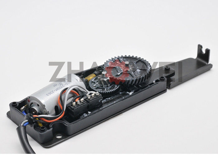
Power lift gate is a back-door system. The system is depicted in Fig. 18.4. The user of the vehicle controls the lift gate opening and closing by pressing a key. The keys are located either on the dashboard or handheld remote. Many power lift gate systems require the touch of a button to work, although hands-free options are becoming more available on a range of vehicles [7]. The hands-free power lift gate also offers intelligent anti-trap, height memory function and other functions.

Power lift gate motor [12]
18.2 Specification
The motors for the specific applications have been designed for both spoke-type and surface-mounted lumbar support motor with same specifications. Table 18.1 depicts the specifications for lumbar motor which satisfies the constraints of low audible voice and overload protection. BLDC motor is designed with the property of low noise and high powers for headrest adjustment, and its specifications are shown in Table 18.2. Power lift gate specifications are depicted in Table 18.3.
18.3 Design Approach
The BLDC motor for spoke type and surface mounted for the applications lumbar support, headrest adjuster and power lift gate has been designed with steel type of stator and rotor core as M36_29G. Ceramic8D is used as its permanent magnet, and for winding, copper is being used as its material.
18.3.1 Stator Design
The number of slots used for both spoke type and surface mounted varies accordingly to the number of poles in order to achieve the design specification. The slot types used for all the models are same, and it is depicted in Fig. 18.5. “Bs0” is kept twice the diameter of the wire as it would be easier for winding. “Bs1 and “Bs2” help to adjust the width of the slots to make slots the adjacent slot to approximately parallel with it. “Bs0” and “Hs0” size variations play an important role in the core losses. “Hs2” varies the depth the slot. For practical convenience, the slot fill factor is to 45%. The slot configuration for the application lumbar support, headrest adjuster and power lift gate is depicted in Tables 18.4, 18.5 and 18.6, respectively.

Stator slot model
18.3.2 Rotor Design
Permanent magnet is mounted on the outer surface of the rotor in two arrangements. Those are surface-mounted and spoke-type model. The major weight and cost of the motor are contributed by permanent magnet. Surface-mounted and spoke-type model are depicted in Figs. 18.6 and 18.7, respectively. Material used for permanent magnet is Ceramic8D; it is insusceptible to demagnetization by outer fields. Ceramic8D is stronger and inexpensive than few natural magnets, thus reduces the overall cost of the magnet. The models are designed with minimum of 0.5 mm gap between the outer diameter of rotor and inner diameter of the stator. The magnets are inserted on the rotating shaft, which in turn maximizes the output traits of the air gap flux density [7]. The magnetic thickness and the magnetic weight have been varied to achieve the output requirements.

Lumbar support surface-mounted model

Lumbar support spoke-type model
18.3.3 Winding Design
The efficiency of whole coiled winding is greater than half-coiled wound motors [8]. To have an efficient motor, the BLDC motors have been designed with whole coiled winding. The winding is depicted in Fig. 18.8. The motors have been designed with two winding layers for all the applications. Lap winding has been used for all the designs. Lap windings are also called as parallel winding. Lap winding has been used for low voltage and also increases the current carrying range.

Lap winding
18.4 Results
Parameters such as output power, input power, efficiency, locked rotor torque, no load speed, maximum efficiency, maximum output power, etc. are compared. The weights of materials used in the rotor and stator like permanent magnet weight, armature copper weight, etc. are also compared to view advantages of motor for different applications.
18.4.1 Lumbar Support
The output results of surface-mounted and spoke-type BLDC lumbar support are shown in Table 18.7; Figs. 18.9, 18.10 and 18.11. The maximum torque in spoke-type model is 0.174 N m which is relatively higher than vividly used lumbar support motors. In spoke-type model, the maximum efficiency of 75% is obtained at the speed of 6800 rpm. In Figs. 18.12, 18.13 and 18.14, comparison of weight between surface-mounted and spoke-type model is depicted. The permanent magnet weight and overall weight of spoke-type model is comparatively lesser than surface-mounted model. The efficiency obtained by surface-mounted model is 7.4176% greater than spoke-type model.

Torque versus speed—lumbar support spoke-type model

Torque versus input DC current—lumbar support spoke-type model

Efficiency versus speed—lumbar support spoke-type model

Efficiency comparison—lumbar support spoke-type and surface-mounted model

Permanent magnet weight comparison—lumbar support spoke-type and surface-mounted model

Total net weight comparison—lumbar support spoke-type and surface-mounted model
18.4.2 Headrest Adjuster
The results of headrest adjuster motor are shown in Table 18.8; Figs. 18.15, 18.16, 18.17, 18.18, 18.19, 18.20 and 18.21. In Fig. 18.15, the torque takes up a parabolic gradual decline as the speed increases. The critical point, i.e., 70% efficiency, is obtained at the rpm of 4000. The spoke-type model has consumed 3.40826 g permanent magnet lesser than surface mounted, in turn spoke-type model has resulted 17.255 g lesser. The weight achieved in comparably lesser than the motors which are widely used. This helps to cut down the cost of the motor slightly. In Fig. 18.21, the flux distribution of the motor is shown.

Torque versus speed—headrest adjuster spoke-type model

Torque versus input DC current—headrest adjuster spoke-type model

Efficiency versus speed—headrest adjuster spoke-type model

Efficiency comparison—headrest adjuster spoke-type and surface-mounted model

Permanent magnet weight comparison—headrest adjuster spoke-type and surface-mounted model

Total net weight comparison—headrest adjuster spoke-type and surface-mounted model

Flux distribution of headrest adjuster spoke-type model
18.4.3 Power Lift Gate
Table 18.9; Figs. 18.22, 18.23, 18.24, 18.25, 18.26 and 18.27 depict the output results of power lift gate design. In Fig. 18.22, there is a steep fall of torque from 0.55 to 0.1 N m, and then the torque reduces gradually. The maximum efficiency is obtained at the speed 11,260 rpm. The spoke-type model has consumed less permanent magnet weight with the difference of 11.7531 g, which can effectively reduce the cost of the motor. The efficiency and overall weight of surface-mounted motor are higher.

Torque versus speed—power lift gate spoke-type model

Torque versus input DC current—power lift gate spoke-type model

Efficiency versus speed—power lift gate spoke-type model

Efficiency comparison—power lift gate spoke-type and surface-mounted model

Permanent magnet weight comparison—power lift gate spoke-type and surface-mounted model

Total net weight comparison—power lift gate spoke-type and surface-mounted model
18.5 Conclusion
In this paper, spoke-type and surface-mounted BLDC motor are designed for lumbar support, headrest adjuster and power lift gate application. We can conclude that the overall permanent magnet weight of the spoke-type model is lesser than surface-mounted model. Ceramic 8D has been used as permanent magnet material in order to reduce the cost of permanent magnet, the major contributor of the overall cost of the motor. The average input current of spoke-type models is greater than surface-mounted model, and the efficiency of surface-mounted model is greater than spoke-type model for all the applications.
18.6 Future Works
Future works can be carried out on designing of BLDC motor on other applications like air pump, window lift drive, anti-lock braking system (ABS), seatbelt pre-tensioner, electric parking brake, etc. The designs can be expanded by using different permanent magnet types. Future works can be done on detailed thermal characterises of motor.
References
D. Uygun, S. Solmaz, Design and dynamic study of a 6 kW external rotor permanent magnet brushless DC motor for electric drivetrains, in 2015 IEEE 5th International Conference on Power Engineering, Energy and Electrical Drives (2015)
L. Chang, J. Muszynski, Design of a 5-phase permanent magnet brushless DC motor for automobiles, in 2003 IEEE 58th Vehicular Technology Conference (2003)
A. Jategaonkar, P. Ramesh, P. Kochgabay, N.C. Lenin, Electromagnetic and thermal analyst is of permanent magnet BLDC wiper motor, in The Advances in Electrical Control and Signal System, AECSS (2019)
P. Shetty, A.K.N. Subramonium, M.S. Kumar, Mathematical modeling of permanent magnet brushless dc motor for electric scooter, in 2015 Fifth International Conference on Communication Systems and Network Technologies, Gwalior, pp. 1222–1226 (2015)
H. Hasan, H. Ismail, R. Mohamed Firhad, R. Azidin, Preventive methods of low back pain, in 2010. International Conference on Science and Social Research (CSSR 2010), Kuala Lumpur, Malaysia (2010), pp. 1278–1282
J. Murgoitio, M. Ferros, A. Goti, M. Larburu, T. Rodríguez, Robotiker-Tecnalia, Networking sensors and actuators for a new active headrest, in Advanced Microsystems f or Automotive Applications, ed. by J. Valldorf, W. Gessner (VDI-Buch, Springer, Berlin, 2007), pp 3–46
A. Müller, K.P. Jankowski, Tailored modeling of a vehicle power liftgate avoiding explicit definition of body-fixed reference frames, in Volume 6: 11th International Conference on Multibody Systems, Nonlinear Dynamics, and Control (2015)
H.-W. Kim, K.-T. Kim, Y.-S. Jo, J. Hur, Optimization methods of torque density for developing the neodymium free SPOKE-type BLDC motor. IEEE Trans. Magn. 49(5), 2173–2176 (2013)
https://images11.palcdn.com/hlr-system/WebPhotos/87/873/8735/8735771.jpg
Author information
Authors and Affiliations
Corresponding author
Editor information
Editors and Affiliations
Rights and permissions
Copyright information
© 2021 The Author(s), under exclusive license to Springer Nature Singapore Pte Ltd.
About this paper

Cite this paper
Ruthra Prakashini, R., Jategaonkar, A., Aasritha, K., Lenin, N. (2021). PMBLDC Motor Design and Analysis for Automotive Applications. In: Kamaraj, V., Ravishankar, J., Jeevananthan, S. (eds) Emerging Solutions for e-Mobility and Smart Grids. Springer Proceedings in Energy. Springer, Singapore. https://doi.org/10.1007/978-981-16-0719-6_18
Download citation
DOI: https://doi.org/10.1007/978-981-16-0719-6_18
Published:
Publisher Name: Springer, Singapore
Print ISBN: 978-981-16-0718-9
Online ISBN: 978-981-16-0719-6
eBook Packages: EnergyEnergy (R0)