
Abstract
The ball-plate system is an unstable open-loop and nonlinear system having 2 degrees of freedom (DOF). This project aims to balance the ball on the plate at the centre or predefined coordinate by adjusting the angle of horizontal plate. The angle of horizontal plate is changed by tilting the plate both in X and Y axes. The actuation is done by two DC servo motors placed in both axes. The feedback of the ball is taken through an overhead camera by processing the images. OpenCV libraries are used for image processing purposes, and Robot Operating System is used as the middleware for the communication between the nodes.
Access provided by Autonomous University of Puebla. Download chapter PDF
Keywords
- 2 DOF ball balancer
- Ball and plate system
- Robot Operating System
- OpenCV
- Image processing
- Control system
- PID controller
1 Introduction
This paper presents the simulation and control of the 2 DOF ball balancer which works on image processing feedback rather than resistive touch feedback. Simulation of the system has been done in the Simulink. The simulations helped for getting a better understanding about the behaviour of the 2 DOF ball balancer. After getting a good simulation result, a system has been fabricated and control algorithms were implemented. In this system, a novel way of communication using Robot Operating System is implemented.
In this system of ball and plate, an overhead camera is placed for getting the feedback of the ball. The camera captures continuous frames of ball which will be processed using OpenCV in order to get the coordinates of the ball. The DC servo motors which are controlled by Arduino actuate the plate. Using the middleware ROS, all the data are communicated between nodes through messages.
Here, the required position of ball is achieved by decreasing the error in the current position and predetermined position. A PID controller is used here for decreasing the error for controlling the position and trajectory of the ball. Using this controller, overshoot due to the high variation in the reference signal is reduced to a limit. In this project, an optimal PID controller is designed resulting in very low rise time, settling time, and negligible steady-state error.
In the literature review, it is found that there are 2 DOF ball balancer which works on the feedback from resistive touch screen or other methods [1]. Those types of feedbacks are very expensive and prone to damage quickly. By implementing a proper vision system, these problems can be solved. There are systems which have implemented vision. But that is through a different software called processing, and the communication is not that fast [2]. This problem is solved through this novel system.
2 Analysis
2.1 Modelling
The free body diagram of a ball on a plate in X-axis is as shown in Fig. 1.

Free body diagram of ball on plate
where mb = the mass of the ball, x = the ball displacement, Fx,r is the force due to ball’s inertia, and Fx,t is the translational force on the ball generated by gravity.
Friction and viscous damping are neglected. The forces acting on the ball by the gravity are depicted as follows:
The force caused by the rotation of the ball is:
where rb = the radius of the ball and τb = the torque which equals τb = Jbϔb(t) where ϒb is the ball angle.
Substituting (2) and (3) in (1) and solving for the linear acceleration gives [3]
2.2 Simulation
Simulations were done using MATLAB-Simulink for the Quanser 2 DOF ball balancer system [4]. Solving the obtained transfer function, corresponding PID controller coefficients’ values were calculated. The control design was for 10% overshoot and 4 s settling time. The result of the simulation was 10.64% overshoot and 4.2 s settling time [5]. The theoretical Kp, Kd, and Ki values are 5.83 rad/m, 2.91 rads/m, and 3.69 rad/ms, respectively. These values were further tuned for the ball to achieve stability, and thus, Kp, Kd, and Ki values were observed to be 7 rad/m, 3.6 rads/m, and 6 rad/sm, respectively. This change in the calculated and observed values is because in simulation the weight of the plate is taken as negligible [6]. Figure 2 shows the servo response, Fig. 3 shows the position response of the ball, and Fig. 4 shows the servo voltage response when an impulse is given. The voltage rating of the servo motor is 5 V. We can see that the simulated result is reaching up to the rated voltage of the servo motor.

Simulated servo angle response

Simulated position response of the ball

Simulated servo voltage response
3 System Overview
The ball and plate system consists of five major hardware components, namely Arduino (Mega), servo motor, Microsoft Lifecam, Lithium polymer battery, and a universal joint. The Arduino (Mega) board offers digital and analog inputs and outputs as well as PWM output which can be programmed using Arduino IDE. The servo motor controls the orientation of the plate. Its position is defined by the width of duty cycle of the PWM pulses arriving from Arduino. The Microsoft Lifecam is used to obtain the visual feedback. The lithium polymer battery is used as the power source, while the universal joint facilitates the movement of the plate along the X and Y axes.
3.1 Hardware
The base and plate of the system are made up of wooden planks. The plate is made in a square shape. It is fixed to the base using a universal joint. This joint facilitates the smooth motion of the plate in both X and Y directions [7]. The end of servo is attached with the plate using a rigid rod. Two PVC pipes joined with a joint are made for mounting the overhead camera. Figure 5 shows the image of the system hardware.

Hardware of the system
3.2 Electrical
In this system, two DC servos are used for actuating the plate in X and Y directions. For the actuation, Arduino Mega development acts as the brain. ROS and Arduino are interfaced using rosserial_arduino making it the subscriber node. Two servos are connected to the microcontroller which subscribes the values of angles that are to be actuated by X-axis servo and Y-axis servo. Those values will be written to the servo so that it rotates to the required angle. Arduino Mega is used because it has more dynamic memory when compared to Arduino UNO. Since Robot Operating System (ROS) utilizes more dynamic memory, it may lead to sync error in development board which has less dynamic memory. Figure 6 shows the schematic diagram of electrical system design.

Electrical schematic diagram of the system
In this system, PID controller is used for decreasing the error [8]. Generally, the midpoint of the plate is fixed as the set point. So, here the error is defined as the difference between the present position and the set point [9]. Then, the error is fed into the PID controller to calculate the PWM that to be sent to the microcontroller to actuate the plate so as to reduce the error that is to balance the ball in the set point. Figure 7 depicts the block diagram of the closed-loop ball-plate system.

Diagram of the closed-loop ball-plate system
3.3 Software
The main software used in this system is OpenCV, ROS, and Arduino IDE. OpenCV and ROS are a set of libraries which are coded in C++ language. OpenCV is used for image processing application [10], and ROS is used as a middleware for the communication between nodes [11]. OpenCV and ROS are interfaced using CVBRIDGE.
Here, mainly there are three nodes:
-
usb_cam node—publishes the images taken by the overhead camera.
-
ball_follower node—subscribes the images published by the usb_cam node and does the required processing publishing the angle to which the servo rotates for minimizing the error.
-
Arduino—angles published by the ball_follower node are subscribed by the Arduino node and will actuate the servo accordingly. Figure 8 depicts the ROS nodes used in the system. Figure 9 shows the ROS node graph which depicts all the nodes and topics which are being subscribed or published.
Fig. 8 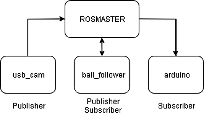
Flowchart of ROS nodes used in the system
Fig. 9 
ROS node graph


The images subscribed by ball_follower node are in RGB colour space. For convenience, it is converted into HSV colour space. Then, the image is thresholded so as to isolate the ball from the surrounding by converting it into a binary image. Figure 10 shows the thresholded image of ball. Then, using moment method, the centre coordinates of the ball can be found out. The middle point of plate is taken as the reference point. The difference between this position of the ball and the reference point is taken as error in the ball’s position which is fed to a PID loop. The output from the PID loop is the angle of both the servos (X-axis servo and Y-axis servo) that to be rotated to minimize the error. The angles are published by the ball_follower node. Figure 11 shows the published angles. These angle values are subscribed by the Arduino node, which actuates the servo to attain the angle.

Thresholded image of ball

Servo angles
4 Results and Discussions
The PID controller designed for the system helped the ball to be balanced at the centre of the plate. The total size of the frame captured by the camera is 320 pixels. Considering the centre of the plate as the reference point, the maximum error in the ball position is 160 pixels. Setting the maximum angle that the servo can rotate to be 120°, we get out Kp coefficient to be 0.75. This was tuned further when implemented on the ball-plate system for its stability. There are some disturbances in the plate due to the vibration of servo motors. Among PID controller coefficients, Ki has very small value making the system a PD controlled system. Overshoot and settling time are minimized. Figure 12 shows the servo angle response when the ball is going to achieve its stable position. Figure 13 shows the final ball and plate system.

Experimental response of servo angle

Final ball and plate system
5 Conclusion
In this paper, the aim was to balance a ball on the top of the plate at the centre or a predefined coordinate by adjusting the angle of horizontal plate. In many of the existing systems, they are using an expensive resistive touch panel for tracking the ball and providing feedback. But here, vision system is implemented in order to track the ball which is less expensive.
There were problems in this system such as removing noise from frames captures, and rejecting disturbances in order to maintain a static ball position balancing. The noises were removed from the images, but disturbances are still there due to the vibration of servo motors.
In this system, a new way of communication system or middleware was used when compared to other ball and plate systems. Integration of information and data using ROS is a novel way.
References
Ali E, Aphiratsakun N (2015) AU ball on plate balancing robot. In: IEEE international conference on robotics and biomimetics (ROBIO), held at Zhuhai, China, 6–9 Dec 2015
Kumar J, Showme N, Aravind M, Akshay R. Design and control of ball on plate system. Int J Control Theory Appl
Sinaga EF, Manurung EB, Chee VA, Djajadi A (2011) Building and controlling a ball and plate system. In: International conference on advances in communication, network and computing, held at Bangalore
Itani A. Ball plate balancing system using image processing. Master of Science thesis in Mechatronics Engineering, Graduate School of Applied Sciences of Near East University
Dusek F, Honc D, Rahul Sharma K (2017) Modelling of ball and plate system based on first principle model and optimal control. In: International conference on process control (PC), held at Slovakia, 6–9 June 2017
Christensen J, Humble J, Mattinson J. Ball-balancing platform design documentation. College of Engineering Utah State University
Quanser Inc. (2013) 2 DOF ball balancer. Students’ Manual pp 5–9
Bang H, Lee YS (2018) Implementation of a ball and plate control system using sliding mode control. IEEE Access, 21 May 2018
Kasula A, Thakur P, Menon MK (2018) GUI based control scheme for ball-on-plate system using computer vision. In: IEEE Western New York image and signal processing workshop, 5 Oct 2018
https://en.wikipedia.org/wiki/OpenCV as on 22 Apr 2019
http://wiki.ros.org/ROS/Introduction as on 22 Apr 2019
Author information
Authors and Affiliations
Editor information
Editors and Affiliations
Rights and permissions
Copyright information
© 2020 Springer Nature Singapore Pte Ltd.
About this chapter

Cite this chapter
Krishnan, K.G., Dutta, K., Eapen, S.A., Martin, M., Jacob, J. (2020). Control of Two Degrees of Freedom Ball Balancer Using Image Processing. In: Saini, H., Sayal, R., Buyya, R., Aliseri, G. (eds) Innovations in Computer Science and Engineering. Lecture Notes in Networks and Systems, vol 103. Springer, Singapore. https://doi.org/10.1007/978-981-15-2043-3_54
Download citation
DOI: https://doi.org/10.1007/978-981-15-2043-3_54
Published:
Publisher Name: Springer, Singapore
Print ISBN: 978-981-15-2042-6
Online ISBN: 978-981-15-2043-3
eBook Packages: EngineeringEngineering (R0)