
Abstract
This research investigated the structural properties (i.e., compressive, tensile, and flexural strength) of different types of ultra-high-performance fiber-reinforced concrete (UHPFRC) with various fibers volume fraction (i.e., 0–4%) and properties compared with a normal strength concrete (NSC) mix. The straight micro steel fibers with aspect ratios (65 and 30) were considered for UHPFRC. The compressive strength exceeded 121 MPa with a water–cementitious material ratio of 0.20 after steam curing. The results of this investigation confirmed that UHPFRC exhibited superior mechanical performance compared to NSC. The increase of fiber volume content showed that mechanical properties of the UHPFRC also increased. It can be seen from the tensile strength tests that NSC and UHPFRC specimen without fiber ended with sudden brittle failure, on the other hand, the specimens made of UHPFRC containing fibers show ductile behaviors. Compressive strength, splitting tensile strength, direct tensile strength, and flexural performance were improved by increasing the fiber volume fraction.
Access provided by Autonomous University of Puebla. Download conference paper PDF
Keywords
- Ultra-high-performance fiber-reinforced concrete
- Mechanical properties
- Normal strength concrete
- Steel fiber
1 Introduction
Ultra-high-performance concrete (UHPC) and ultra-high-performance fiber-reinforced concrete (UHPFRC) was originally developed in the early 1990s by Bouygues laboratory in France by the name of reactive powder concrete (RPC) [8]. UHPFRCs are a new generation of cementitious composites with excellent material properties (i.e., compressive strength >150 MPa and tensile strength >8 MPa) and exhibit strain-hardening behavior under uniaxial tension [1]. UHPFRC is mainly characterized by high strength and exhibits high ductility when reinforced with steel fibers. The material used in UHPFRC is different from the ordinary concrete. The main constituents are (1) cement (2) well graded fine sand (3) quartz sand (4) silica fume or other mineral admixture (5) steel fiber (6) high-range water-reducing agent. The common mix of UHPFRC is summarized in Table 1.
Curing of UHPFRC is also different from the traditional concrete. Three different types of curing are used, i.e., at room temperature, about 90 °C of high-temperature and steam curing at 200 °C. Under normal circumstances, the strength of concrete at 27 °C temperature is 10–30% lower than that of 90 °C. Although at steam curing (>200 °C) can achieve a higher strength,due to equipment restrictions the first two curing methods are used [2]. The dosage of cement in UHPFRC is generally higher than 1000 kg/m3 to achieve ultra-high strength with very low w/c ratios. The use of high content cement not only affects the total cost of concrete, but also has negative effects on the heat of hydration that may cause shrinkage problems. The use of mineral admixtures can be a feasible solution to overcome these problems. To achieve tremendous mechanical properties, Richard and Cheyrezy [9] suggested some special procedures and raw materials adopted in the preparation of UHPFRC
-
1.
Homogeneity of concrete enhanced by removing the coarse aggregate.
-
2.
Steel fibers are introduced to improve the ductility of composites.
-
3.
High-Range Water-Reducing Agent (HRWRA), a large amount of silica fume and very fine quartz sand are used to achieve a low w/b ratio to reduce porosity and improve strength.
-
4.
Pressure may be applied before and during the setting to increase the compactness of the concrete.
-
5.
Steam curing may be supplied to increase higher early strength.
The main objective of this research is to determine the mechanical properties of UHPFRC, i.e., uniaxial compressive, splitting tensile, direct tensile, and flexural strength.
2 Experimental Program
2.1 Materials and Specimen Preparation
The mix proportions used in this study are summarized in Table 2. For NSC, OPC-53 Grade cement, locally available river sand and a coarse aggregate (size = 10 mm) were used and for UHPFRC cementitious materials, OPC-53 grade cement with a specific surface area 3413 cm2/g and density 3.15 g/cm3) and silica fume (a specific surface area 200,000 cm2/g and density 2.10 g/cm3) were used. The use of silica fume in UHPFRC is increasing the strength via the pozzolanic reaction and fills the voids. The detailed chemical compositions and physical properties of the cementitious materials are given in Table 3. Sand with a grain size smaller than 0.6 mm was used as the fine aggregate. The coarse aggregate is not used in the mix to improve the homogeneity. For obtaining suitable fluidity and viscosity, an HRWRA with a density of 1.01 g/cm3 was included. The mean particle sizes of the components illustrated in Fig. 1 were determined based on the packing density theory and results from rheological and mechanical tests. Two different sizes of high strength (2600 MPa) brass-coated straight steel fiber were used throughout this study, with the properties summarized in Table 3. The fibers were embedded in three different UHPFRC mixes, whose composition is summarized in Table 2.

Mean particle sizes of ingredients in UHPFRC [13]
The mixing sequence was as follows: cement, silica fume, and sand were first premixed for approximately 10 min. After that, water premixed with HRWRA was added in the dry state and mixed for another 10 min. When the mixture exhibited adequate flowability and viscosity, steel fibers were dispersed and then mixed for another 5 min (Table 4).
2.2 Test Setup and Procedure
2.2.1 Compression Test
One of the most commonly specified and measured properties of concrete is compressive strength. In compliance with the IS: 516–1959 [5] standard, the compressive strength test was performed on the cubic samples with an array dimension of 70.6 × 70.6 × 70.6 mm. The arithmetic mean of minimum three samples for each mix was calculated to evaluate the compressive strength after 7th and 28th day. The compressive load was monotonically applied using a compression testing machine (CTM) with a loading rate of 3 kN/s and the maximum load capacity of CTM is 3000 kN.
2.2.2 Four-Point Flexural Test
Flexure strength is one of the measures of the tensile strength of concrete. It is a measure of unreinforced concrete beam or slab to resist failure in bending. UHPFRC exhibits high flexural strength properties due to its dense particle packing and the presence of steel fiber [4]. Three prismatic beams for each mix were cast to investigate and compare the flexural behavior of UHPFRC and NSC under four-point static loading condition with varying percentage of fiber (0–4%).Totally, 15 beam specimen (500 × 100 × 100 mm) were cast with a clear span 400 mm. The universal tensing machine (UTM) used for the flexural tests at a loading rate of 1 KN/s. To measure the mid-span deflection, a steel frame with two LVDTs was installed at the center of the beam as shown in Figs. 2 and 3. The flexural test continued until cracks appear and failure happens.

Test setup for the four-point flexural test

Distribution of moment, shear, and cracks along the beam
2.2.3 Splitting Tensile Test
A total of 15 cylindrical specimens (three for each mix) were cast to determine the splitting tensile strength of concrete. According to IS: 5816 – 1999 [6], the cylinder size was Ø100 X 200 mm. After applying the load, the surface was smoothed with a sandpaper to avoid eccentricity effect. In splitting tensile test, the sample was placed with its horizontal axis between the cylindrical platens of a testing machine. The load was increased until failure took place by indirect tension in the form of splitting along the vertical plane. The compressive load was monotonically applied using a compression testing machine (CTM) having a capacity of 3000 kN.
2.2.4 Direct Tensile Test
The direct tensile test is a uniaxial test in which the tensile strength of concrete is determined by pull out the specimen apart. No standardized test for quantitative determination of the full range of UHPC tensile behaviors exists in India. The dog-bone-shaped specimen was made with a 300 mm length, 35 mm thickness and 1535 mm2 cross section at mid-span as shown in Fig. 4.

Dog-bone specimen geometry used for both materials in the direct tension tests (all dimensions in mm)
3 Experimental Results and Discussion
3.1 Compressive Behavior
The compression tests were carried out on a standard 70.6 mm cubic specimens after curing at the ages of 7 and 28 days for each mix. The test procedure was carried out using the 3000 kN capacity compression testing machine (CTM). The results obtained from experimentally is shown in Table 5. The compressive strength bar chart for NSC and UHPFRCs obtained is shown in Fig. 5. The results indicate that after 28 days of curing, the compressive strength is 121 MPa for M3 mix (volume of steel fibers is 4.0%) while 28 days compressive strength was obtained 35 MPa for NSC mix (Fig. 6).

Bar chart for compressive strength of different mixes

Mode of failure of cube specimen with and without fiber

Bar chart for flexural strength of different mixes

Load–deflection curve for NSC and UHPFRCs
3.2 Flexural Behavior
500 × 100 × 100 mm beams were used for the flexural test (as shown in Fig. 2). The beams were placed on the roller supports with the vertical-molded faces located at the compression and tension faces. To ensure low horizontal forces due to support friction, the specimens were supported by steel rollers. The load was then applied via the hydraulically controlled constant loading rate 1 kN/s at the middle span through failure. Figure 9 shows the typical UHPFRC and NSC beams after testing. It was noted that in the case of UHPFRC, the beam remains intact due to the presence of the steel fibers while NSC beams failed in brittle behavior. The average result of the flexural strength from the flexural test of UHPFRC and NSC were represented in Table 6. The load-displacement behavior of NSC and UHPFRCs obtained experimentally as shown in Figs. 8, 7 and 10).

UHPFRC and NSC specimens after testing

Flexural strength test setup
3.3 Splitting Tensile Behavior
The split tensile test conducted according to IS 5816: 1999 [6]. By increasing the percentage of steel fiber in UHPFRC increases the split tensile strength under static loading condition as shown in Table 7. The split tensile strength was computed from the following relation:
where
- ƒ t :
-
is the split tensile strength (MPa)
- P :
-
is the magnitude of the load at failure (kN)
- D and L:
-
are the cylinder diameter and length respectively (mm) (Figs. 11, 12, 13).
Fig. 11 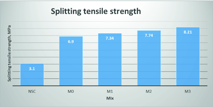
Bar chart for split tensile strength for various types of mixes
Fig. 12 
Schematic picture of split tensile test setup
Fig. 13 
Cylinder specimen after split tensile test


3.4 Direct Tensile Behavior
Three dog-bone shaped specimens of each mixture were cast. After the 28 days curing, the specimens were tested to find the direct tensile behavior. The test results show that NSC and UHPC specimen ended with sudden brittle failures. On the other hand, the specimens made of UHPFRC show ductile behaviors. The direct tensile strength of various mixes is shown in Fig. 14. It can be clearly seen in Table 8 that mean maximum tensile strengths are 6.2 MPa for M3 mix and 1.14 MPa for NSC mix.

Bar chart of direct tensile strength for various mixes
4 Conclusions
The mechanical properties of UHPFRC specimens were experimentally investigated with varying fiber volume contents and the results are compared with the NSC mix. Based on the results obtained, the following conclusions can be drawn:
-
The steel fibers play an important role to improve the mechanical performance of UHPFRC.
-
The compressive, tensile, and flexural behaviors were improved by the addition of micro steel fibers and the effectiveness increases when the number of fibers increases.
-
The compressive strength of UHPFRC is significantly higher than NSC. The compressive strength of M3 mix increased up to 17.47% as compared to M0 mix and 3–4 times higher than NSC mix.
-
Without steel fibers, it exhibits explosive failure in compression and brittle failure in tension, on the other hand, the specimens made of UHPFRC containing fibers show ductile behaviors.
-
Ultimate flexural strength increased up to 3 times when compared to NSC and 2 times higher than the M0 mix. Both tensile strengths (split and direct tensile strength) were improved by the addition of steel fibers and the maximum strength was obtained for M3 mix at 4% fiber volume content.
-
In the case of UHPFRC specimens, a higher tensile strength and ductility of the material compared to NSC was observed (i.e., 2–4 times higher). This is a result of a strong interlocking force between steel fibers and concrete matrix after the ultimate tensile capacity.
Briefly, the results demonstrate that the superior material properties of UHPFRC when compared to normal concrete in both compression and tension. Thus, the results obtained with the different fiber volume fractions used in this study appear a promising material for use of UHPFRC in future.
References
AFGC. (2013). Ultra high performance fibre-reinforced concretes (p. 358). France: InterimRecommendations, AFGC publication.
Deng Z.-C., Xiao, R., & Shen, C. (2013). A review on preparation and properties of ultra-high performance concrete. Materials Review, 9, 66–69.
Fehling, E. S. (2008). Second International Symposium on Ultra-High-Performance Concrete, Kassel, Germany. In Second International Symposium on Ultra-High-Performance Concrete, Kassel, Germany (p. 902). Kassel, Germany: Second International Symposium on Ultra-High-Performance Concrete, Kassel, Germany.
Graybeal, B. A., & Hartmann, J. L. (2003). Strength and durability of ultra-high performance concrete. In Concrete Bridge Conference (p. 20).
IS 516–1959. (1959). (Reaffirmed 2004), Methods of Tests or Strength of Concrete. New Delhi: Bureau of Indian Standards.
IS: 5816–1999 (1999). (Reaffirmed 2004), Splitting Tensile Strength of Concrete - Method of Test. New Delhi: Bureau of Indian Standards.
Lachance, F. C. (2016). Development of precast bridge slabs in high-performance fiber-reinforced concrete and ultra-high-performance fiber-reinforced concrete. ACI Structural Journal, 113(5), 929–939.
Richard, P., & Cheyrezy, M. (1994). Reactive powder concrete with high ductility and 200–800 MPa compressive strength. ACI, 144, 507–518.
Richard, P. C., & Cheyrezy, M. (1995). Composition of reactive powder concretes. Cement and Concrete Research, 25(7), 1501–1511.
Schmidt, D. D. (2004). Fire resistance of ultra-high performance concrete (UHPC)—testing of laboratory samples and columns under load. In Proceedings of the International Symposium on UHPC, Kassel, Germany (pp. 703–715). Kassel, Germany: In Proceedings of the International Symposium on UHPC, Kassel, Germany.
Schmidt, M. F. (2012). Ultra-High Performance Concrete and Nanotechnology in Construction. Kassel, Germany: Third International Symposium on UHPC and Nanotechnology for High-Performance Construction Materials, Kassel, Germany.
Talebinejad, I. I. (2004). Optimizing mix proportions of normal weight reactive powder concrete with strengths of 200–350 MPa. In Proceedings of the International Symposium on UHPC, Kassel, Germany (pp. 133–141). Kassel, Germany: In Proceedings of the International Symposium on UHPC, Kassel, Germany.
Yoo, D. Y., Zi, G., Kang, S.-T., & Yoon, Y.-S. (2015). Biaxial flexural behavior of ultra-high-performance fiber-reinforced concrete with different fiber lengths and placement methods. Cement and Concrete Composites, 63, 51–66.
Author information
Authors and Affiliations
Corresponding author
Editor information
Editors and Affiliations
Rights and permissions
Copyright information
© 2019 Springer Nature Singapore Pte Ltd.
About this paper

Cite this paper
Gangwar, S., Mishra, S., Sharma, H.K. (2019). An Experimental Study on Mechanical Properties of Ultra-High-Performance Fiber-Reinforced Concrete (UHPFRC). In: Das, B., Neithalath, N. (eds) Sustainable Construction and Building Materials. Lecture Notes in Civil Engineering , vol 25. Springer, Singapore. https://doi.org/10.1007/978-981-13-3317-0_78
Download citation
DOI: https://doi.org/10.1007/978-981-13-3317-0_78
Published:
Publisher Name: Springer, Singapore
Print ISBN: 978-981-13-3316-3
Online ISBN: 978-981-13-3317-0
eBook Packages: EngineeringEngineering (R0)