
Abstract
Static analysis of programs is essential for better understanding towards software maintenance and re-engineering. Unfortunately, we still lack automatic tools to understand the back end of the programs (Bytecode). Developing these tools is very expensive and time-consuming task but it is today’s need. Those tools may help to understand Java Bytecode. Some time source code is not available all the time but bytecode is easily available. Unfortunately, bytecode is not understandable by many of us so that we are providing a little effort in this regard. This article represents the program flow execution in Java Bytecode. We present static and dynamic path executions of programs in a bytecode using Control Flow Graph (CFG) and Data Dependence Graph (DDG). Bytecode analysis is an effort to develop a tool which can make visualization of Java programs in back end form.
Access provided by CONRICYT-eBooks. Download conference paper PDF
Keywords
- Static analysis of programs
- Program dependence graph
- Control flow graph
- Software testing and maintenance
1 Introduction
Program execution is the process of control flow information towards output. It shows the behavior of programs in a dynamic way. Mainly, there are two ways of analysis of programs they are static and dynamic. Static analysis provides all text of programs and more path execution which can make some heuristics about programs. Dynamic analysis provides exact execution which is a dynamic path of the program during runtime. In our paper, we are dealing with both approaches towards path executions. We present the Control Flow Graph (CFG) and Data Dependence Graph (DDG) from Java Bytecode which are better for developing tools of software testing and maintenance in future. Currently, we are lacking those tools which can provide information of whole programs in visual forms and that can be better for understanding of programs.
Program analysis is the process of verification of data flow and control flow information from programs [1]. This is although very active research area and many tools [2, 3] have been developed for the programs but unfortunately, all tools work on front end (Source Code) of programs. Mainly all tools are used for the source code but there are few tools [4], which have been developed for Java Bytecode for understanding and representation of data and control flow analysis. This area of research still needs more focused time so that people can get benefit from the back end (Bytecode) analysis which may reduce the cost of program maintenance and re-engineering. At [5, 6], static analysis of Java Bytecode and Dependence analysis is presented which are essential for the understanding of computer programs. It may prove helpful for many software engineering tasks like testing, debugging, reverse engineering, and maintenance. Our approach presents new approach to building back end (Bytecode) tools for the Java Bytecode programs and may be helpful for upcoming automatic tools towards software testing, debugging, maintenance, and reverse engineering. The authors provided specification based model for the abstract dependencies from Java programs which helps towards finding faults and localizing faults [7,8,9]. The visualization of data through software requirement [7] is presented. To the best of our knowledge, our technique may help further to investigate program analysis and help towards debugging [10] in a bytecode.
This article makes use of static and dynamic analysis of programs in terms of bytecode analysis. In our approach, we have presented executions of programs, showing the Control Flow Graph (CFG) and Data Dependency Graph (DDG). A Control Flow Graph (CFG) presents the execution paths in a program using graph notations. It shows exactly the traversing of all statements of the program during execution. In a Control Flow Graph (CFG), the program statements are converted into nodes and edges, nodes show the basic blocks of the statements and edges show the control from one statement to another statement. There are, in most presentations, two specially designated blocks: the entry block, through which control enters into the flow graph, and the exit block, through which all control flow leaves. In our work, we are extracting edges and nodes from bytecode of the Java programs which helps in static and dynamic analysis of programs from the back end (Bytecode). Furthermore, we have presented Data Dependence Graph (DDG) from the bytecode which presents the constraints on how a piece of code can be reorganized in term of dependency. Furthermore, data dependency shows the relationship of the variables in a program.
The rest of this paper is organized as follow. Section 2 contains information of Java Virtual machine and Bytecode Information. Section 3 contains program execution information. Section 4 contains Control Flow Graph (CFG) from bytecode. Section 5 extracted Data Dependence Graph from the bytecode. Section 6 contains Related Research. Finally, conclusion and future research are depicted in Sect. 6.
2 Java Virtual Machine (JVM) and Bytecode Understanding
This section gives an overview about Java Virtual Machine (JVM) and bytecode information from the Java source code. The Java Virtual Machine (JVM) is a load based virtual machine which can support Java programming language [11]. It is an independent platform for the input of class files. Each class is a binary file which contains information about fields and methods. Java Programs are compiled into bytecode called as machine language of JVM which also provides opcode and operands in bytecode information [12]. The JVM is responsible for loading all relevant class files upon execution of program. At runtime, the JVM fetches opcode and corresponding operands and executes the corresponding actions accordingly [5]. Java Bytecode is an object code of Java program [13]. In a bytecode, it shows the line number, opcode and operands with complete information of variables used with reference numbers. Also, it provides prefixes to all statements used in source code of Java program. For example, if we used declaration of any data type in the source code then bytecode provides prefix with values assigned. For example int \(i = 3\) represented in a bytecode is ICONST3, i declares the integer type of the variable and CONST shows that variable declaration and assigned value is 3. It also provides line number with ISTORE information, which is used for integer storage in the memory stack. So always in a bytecode, it includes the prefix information, line number, memory storage and label number which may count as line number in our idea. For basic and complicated statements of source code, compiler provides information in a bytecode with reference number, opcode, and corresponding operands.
3 Path Executions
This section contains information of the program execution and representation in control flow graph and data dependence graph from the back end (bytecode). There are two kinds of the execution of programs named as static and dynamic.
-
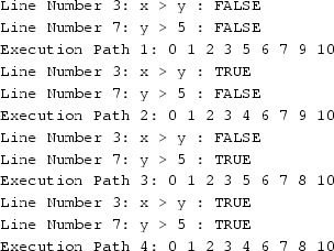
Static Execution: It provides whole text of the program for analysis. Static always provides all information of program having all control flow possibility according to the source code. In Java program, we extracted all possible path executions. In the program, we found four path executions according to true and false values for those conditions. We have shown the static path executions of our program (Fig. 1) as follows:
-
Dynamic Execution: It provides the exact flow control of program according to source code of program execution. It depends on compiler to compute and execute program statements based on the input values and other control flow statements of the program. We have presented dynamic execution path of our program (Fig. 1) as under:-


4 Control Flow Graph
A Control Flow Graph (CFG) is a graph which represents control through whole program. It contains nodes of program which represents statements while edges show the flow of control between statements.
In the Fig. 1, an example of Java program is written and we have shown the execution passing through all paths. In Table 1 we have shown each bytecode statement of the Java Program, source code, basic blocks, and nodes for the graph. However, we have extracted source code and provided bytecode in the Table 1 is for understanding of the execution of Java programs. Our approach is to derive control flow graph and dependence graph from its bytecode. We have extracted all bytecode statements from the source code and have made blocks and nodes of all statements. Once program has been compiled, we analyzed bytecode. In Table 1, there are four columns, one column shows bytecode information, second represents source code, third column shows the basic blocks, and the last column shows the nodes for the graph. We recognize nodes according to entry and exit point of control flow execution of program.
Always we start from the first node and leader of the control flow graph. The leaders of all blocks have to be recognized through control flow from its entry and exit point. First, it begins with simple statements and making basic blocks for all the bytecode instructions. The basic block is defined as a block consisting of sequence of instructions where entry and exit point are only in one direction. So simple statement and multiple statements are sequentially treated as one node in the control flow graph. For example, we have made one node for all the sequence statements in our example program. In the Table 1, B1, B2 and B3 are counted as one node because of sequence of statements and no edges.

Java test program

Control flow graph of bytecode execution

Data dependence graph of bytecode execution
For those statements which have more than one edge then each statement is counted as a node. All conditional, calling methods statements in a program are counted individually and are assigned node for every edge in between. Each conditional instruction of program is counted as also leader so that we have given representation as node. If there is if, while or other comparative statements, also they are counted as leaders. The branch values of these leader are true and false. Each instruction of method calls and return also counted as leaders. After counting all instructions of programs we have assigned leaders and fixing the nodes. Once all bytecode instructions are represented in the form of nodes, the control flow graph works through all possible path executions. Also, we never count node of any return statements which may not return any value so we have reduced that block from the control flow, as it does not show impact on the flow of program and as well as result of the program.

In Fig. 2, for the building CFG from the bytecode, we use nodes which are created from blocks. We are not considering \(else, if, return, \{, \}\) and those which cannot make impact on the output of the programs. We are extracting nodes from the basic blocks from Table 1 and did not even count some basic blocks which are making from nonstructuring statements like \(else, if, return, \{, and \}\). Our Algorithm 1 is to recognize the line numbers from bytecode and nodes which are created from blocks. After that we follow path execution of program in bytecode statically and dynamically as we have discussed in Sect. 3. We have presented below static and dynamic execution of paths according to nodes representation in the Fig. 2 as follows:-
-
Path 1: N1, N2, N4, N5, N6, N8 and N9
-
Path 2: N1, N2, N3, N5, N6, N8 and N9
-
Path 3: N1, N2, N4, N5, N6, N7 and N9
-
Path 4: N1, N2, N3, N5, N6, N7 and N9
In the above information path, 1, 2, 3, and 4 are static paths. Also, path 1 is counted as dynamic path because of compiler execution according to values in the program. We have extracted all information from bytecode and built blocks and nodes from program lines. After that nodes and blocks are presented in CFG which is shown in Fig. 2.
5 Data Dependence Graph (DDG)
The Data Dependence Graph (DDG) is derived from assignment of variables which shows dependence relation in between. We extract information from bytecode and make blocks of each lines. We have given names to each block and counted dependencies of it. One block to another block we consider variable which may impact on another variable in a block. We have inspected each block in a Java Bytecode in terms of values in variables. In Java code, \(x = 3\) which represents L0 LINENUMBER ICONST 3 ISTORE 1 in bytecode. We calculated data dependencies according to given line number of each bytecode statements. Furthermore identify the names of variables, line numbers and uses of those variables in another block. We have identified the data flow of variables from one block to another block in a graph 3.
In Fig. 3, we have made blocks from all statements including simple, multiple and conditional. Blocks consist of all lines with variables and values. The simple lines show the control flow of the program and dotted lines show the dependency of variables on different blocks. For example in the block number 3, variable z is used which can change in others blocks due to data dependency. We have shown in the Fig. 3 all variables dependencies according to blocks wise.
6 Related Research
In [14], a library that enables bytecode transformations by strategic rewriting has been presented using the language TOM. Mapping of bytecode programs to algebraic terms is done. Pattern matching and strategic programming primitives to the existing language is added to express bytecode transformations.
In [15], Fixpoint algorithms was used for analyzing the bytecode considering a number of optimizations in order to reduce the number of iterations. The term parametric is used as the algorithm is independent of abstract domain and it can be applied to different domains.
In [16], authors carried research work to discussed challenges faced by bytecode analyzers. With various example programming statements, the relation between low level and high level analyses using the concepts of strong and weak relative completeness have been formalized.
In [17], a framework for java program analysis called Soot was discussed. Various features of the framework were discussed which can be used for program analysis.
We have presented analysis technique and show how we can extract bytecode information from the code and represent it in control flow graph and data dependence graph. It is being good to understand the back end of the program. As we cannot find much material on understanding of bytecode our research may help to understand bytecode information.
7 Conclusion and Future Research
We have presented static and dynamic execution of programs from Java Bytecode instructions. It is essential for better understanding towards software maintenance and reengineering. Our article represents the program flow executions in Java Bytecode. We presented Control Flow Graph (CFG) and Data Dependence Graph (DDG) from bytecode information. We believe that our discussion and idea may help researchers to develop advance tools for understanding back end code of programs.
Future research has to develop tool of our presented idea and hope it may help for software debugging and testing community in future, which is really today’s need in the world.
References
Sreedhar, V.C.: Efficient Program Analysis Using DJ Graphs. Doctoral Dissertation. McGill University, Canada (1995)
Java Checker. http://www.gradsoft.ua/products/javachecker_eng.html
Static Analysis Tools Exposition (SATE). http://samate.nist.gov/SATE.html
Dr. Garbage. http://www.drgarbage.com
Zhao, J.J.: Static analysis of bytecode. Wuhan Univ. J. Natural Sci. 6(1–2), 383–390 (2001)
Zhao, J.J.: Dependence analysis of java bytecode. In: Proceeding COMPSAC 24th International Computer Software and Applications Conference, pp. 486-491. IEEE Computer Society Washington, DC, USA (2000)
Soomro, S., Abdul, H., Syed, H.A.M., Asadullah, S.: Ontology based requirement interdependency representation and visualization. In: Communication Technologies, Information Security and Sustainable Development Communications in Computer and Information Science vol. 414, 2014, pp 259–270, pp. 486–491. CCIS Springer Series (2013)
Soomro, S., Wotawa, F.: Detect and localize faults in alias-free programs using specification knowledge. In: LNAI Springer Series , IEA/AIE 2009, LNAI 5579, pp. 379–388 (2009)
Soomro, S.: Using abstract dependences to localize faults from procedural programs. In: Proceedings Artificial Intelligence and Applications, Innsbruck, Austria, pp. 180185 (2007)
Weiser, M.: Programmers use slices when debugging. Communications of the ACM 25(7), 446452 (1982)
Arnold K., Gosling, J.: The Java Programming Language, Addision Wesley (1996)
Don, L., Roland, H.U., Nancy J.W.: Bytecode-based java program analysis In: Proceedings of the 37th Annual Southeast Regional Conference , ACM Southeast Conference, Mobile, AL, April 15–18 (1999)
Peter, H.: Java Bytecode (2001). https://www.ibm.com/developerworks/ibm/library/it-haggar_bytecode/
Ballad, E., Moreau, P.E., Rellies, A.: Bytecode rewriting in Tom. In: Second Workshop on Bytecode Semantics, Verification, Analysis and Transformation–Bytecode 07 Braga/Portugal (2007)
Maendez, M., Jeorge, N., Hermenegildo, M.V.: An Efficient, Parametric Fixpoint Algorithm for Analysis of Java Bytecode. Published in Electronic Notes in Theoretical Computer Science (2007). https://www.elsevier.nl/locate/entcs
Logozzo, F., Fahndrich, F.: On the relative completeness of bytecode analysis versus source code analysis. In: Published in 17th International Conference, CC 2008, Held as Part of the Joint European Conferences on Theory and Practice of Software, ETAPS 2008, Budapest, Hungary, March 29–April 6 (2008)
Lam, P., Bodden, E., Lhotak, O., Henden, L.: The Soot Framework for Java Program Analysis: a Retrospective. Published in Cetus Users and Compiler Infastructure Workshop ETUS (2011)
Author information
Authors and Affiliations
Corresponding author
Editor information
Editors and Affiliations
Rights and permissions
Copyright information
© 2018 Springer Nature Singapore Pte Ltd.
About this paper

Cite this paper
Soomro, S., Alansari, Z., Belgaum, M.R. (2018). Path Executions of Java Bytecode Programs. In: Saeed, K., Chaki, N., Pati, B., Bakshi, S., Mohapatra, D. (eds) Progress in Advanced Computing and Intelligent Engineering. Advances in Intelligent Systems and Computing, vol 564. Springer, Singapore. https://doi.org/10.1007/978-981-10-6875-1_26
Download citation
DOI: https://doi.org/10.1007/978-981-10-6875-1_26
Published:
Publisher Name: Springer, Singapore
Print ISBN: 978-981-10-6874-4
Online ISBN: 978-981-10-6875-1
eBook Packages: EngineeringEngineering (R0)