
Abstract
Advanced resin matrix composites are referred as a class of composites constructed by matrix resins and continuous fiber reinforcements. Advanced resin matrix composites can provide a series of extraordinary advantages including high specific strength and stiffness, designable properties, fatigue and corrosion resistance as well as special electric–magnetic performance.
Access provided by CONRICYT-eBooks. Download chapter PDF
Advanced resin matrix composites are referred as a class of composites constructed by matrix resins and continuous fiber reinforcements. Advanced resin matrix composites can provide a series of extraordinary advantages including high specific strength and stiffness, designable properties, fatigue and corrosion resistance as well as special electric–magnetic performance. Compared with traditional steel and aluminum alloys, the density of composites is only about 1/5 that of steels and 1/2 that of aluminum. Therefore, the specific strength and modulus of these composites are obviously higher than those of steel and aluminum alloys. Using composites to replace aluminum and other metal materials can significantly decrease structure weights [1].
In addition to superior performance in processing technologies, advanced resin matrix composites can provide integrated one-step processing even for complex structural shapes and for large size parts. They offer many benefits in terms of significantly reducing the number of components in structural parts, eliminating too many joints, greatly decreasing stress concentrations, saving processing steps and machining work, thus reducing raw material quantities and costs. Because of their unique advantages, advanced resin matrix composites are applied in the aerospace, sporting goods and other industries. They have become a class of important composite materials with fast-growing and widespread applications [2].
The mechanical and physical properties of advanced resin matrix composites depend on the types and content of fibers, fiber orientations, laminating sequences and numbers and are also closely related to the resin matrixes used. The maximum service temperature, environmental effect resistance, mechanical and electric performance will largely depend on the resin matrix used.
In this chapter, we introduce the types and features as well as the suitable ranges and applicable technologies of the resin matrix materials selected for advanced resin matrix composites. Some achievements from high-performance resin matrix studies and applications in China will also be discussed.
3.1 The Performance of Composite Resin Matrixes
When used for composite matrixes, high-performance resin systems must satisfy the requirements of practical engineering applications including processing ability, thermal, physical and mechanical properties. The processing performance of resin matrixes will include their dissolution in solvents, melting viscosity (flow ability) and change in viscosity behavior (processing windows). The thermal resistance includes the glass transition temperature (T g), thermal–oxidant stability, thermal decomposition temperature, flame-retardant performance and thermal deformation temperature, which can dominate the composite service temperature ranges. The discussion about the mechanical properties of resin matrixes will cover their property specifications under service conditions such as tensile strength, compression, bending properties, impact resistance and fracture toughness. Resin matrixes should have very good electric properties and chemical resistance including solvent resistance, self-lubrication and anti-corrosion properties. For resins to be used in optical fields, their refractive index, transparency, color, weather and optical–chemical stabilities should be taken into account [3, 4].
3.1.1 Thermal Resistances
-
(1)
Glass transition temperature
The glass transition is a secondary transition in which polymers will transit from a glass state into an elastic state. At temperatures lower than the glass transition temperature, polymers will be subject to a series of changes including sudden changes in specific heat and capacity, movement of molecular chain segments and the fast growth of linear expansion coefficients. In polymer chains, the existence of strong polar groups will increase the interaction forces between molecules, which further increases chain densities, and as a result, polar polymers will possess a higher T g. In polymer main chains and side groups, huge rigid groups can inhibit chain segment free rotation, which is useful for an increase in T g, while flexible side groups can increase the distance between chains and allow them to move more easily, resulting in a decrease in T g. Therefore, to increase the T g and the thermal resistance the resin matrixes of advanced composites will normally be designed to contain a large quantity of chains with huge rigid groups.
-
(2)
Thermal–oxidant stability
To meet the requirements of aerospace applications, high-temperature-resistant resin matrixes that can tolerate long-term temperature exposure, even as high as 300 °C, have been developed. Dynamic thermal gravimetric analysis (TGA) can be used to determine the short-term thermal resistance and the thermal–oxidant stability. The long-term thermal–oxidant stability of resin matrixes should be determined by a high-temperature long-term aging test. Thermal–oxidant stability depends on the bond energy between the atoms that constitute the molecular chains. Aromatic and heterocyclic structures like phenyl and nitrogen hetero-naphthalenes have a high bond energy and can provide high thermal–oxidant stability.
The most stable polymers are ladder polymers composed of heterocyclic and aromatic conjugate structures. The most stable flexible chain groups are aliphatic compounds in which all the hydrogens are substituted by fluorine and phenyl. –O–, –S–, –CONH– and –CO– can also give good thermal–oxidant stability; –SO2–, –NH–, hydroxyl and chloride groups impart lower thermal–oxidant stability. The thermal–oxidant stability of xylene-containing polymers increases as follows: p > m> o. Generally, cross-linking can improve polymer thermal–oxidant stability.
3.1.2 Coefficient of Thermal Expansion (CTE)
The combination of two materials with different CTE will cause interface stress when the temperature changes. If this difference in CTE is large, the interfacial bond can be damaged. Composites are composed of resins and reinforcing fibers. Stress can be generated at the resin and fiber interface as the temperature changes, possibly resulting in delamination by severe stresses. Adhered structures are also easily damaged at the adhering interface. Therefore, for high-performance resin matrixes, CTE matching of reinforcing materials should be seriously taken into account.
CTE can be determined by thermal mechanical analysis (TMA). In Table 3.1, some commonly used composite resin matrixes and reinforcing materials are given with their CTE. In general, inorganic materials have a lower CTE than polymeric materials. To decrease the CTE of polymers, the following methods can be adopted:
-
(1)
Introduce ordered structures such as crystals into the polymers.
-
(2)
Use huge rigid structures like aromatic heterocyclic structures to reduce polymer molecular segment movement.
-
(3)
Increase cross-linking density.
3.1.3 Mechanical Properties
The mechanical properties of high-performance resin matrixes are mainly characterized by tensile strength and modulus, fracture elongation, bending strength and modulus, impact strength and surface hardness. These properties will change as the temperature, processing and cure conditions change. Compared with other structural materials, an important property of a high-performance resin matrix is its viscoelasticity, that is, its behavior is dependent on applied temperature and time. Because of the existence of viscoelasticity, polymeric materials, especially thermoplastic resin matrixes, will be subject to creep and stress relaxation during working processes.
High-performance resin matrixes with a rigid backbone will have a macromolecular main chain that contains a large amount of aromatic heterocyclic structures, and some conjugated double bonds will be arranged in an ordered ladder structure, and the molecules will have good regularity or a high cross-linking density. Therefore, high-performance resin matrixes generally have a high modulus, but their fracture elongation and toughness are relatively lower. Table 3.2 lists some high-performance resin matrixes and their mechanical properties.
Improving the toughness of high-performance resin matrixes can be carried out by two ways:
-
(1)
Introduction of a flexible chain segment into main chain structures or reducing the cross-linking density, but this may result in a decrease in resin thermal resistance.
-
(2)
Introduction of a secondary phase into the resin matrix.
3.1.4 Electric Properties
High-performance resins are increasingly used in the electronics industry as insulating materials and wave transparent materials. Therefore, understanding the electric properties of high-performance resins is of great significance.
For engineering materials, the electric properties of interest are the dielectric properties and the electric breakdown intensity. The dielectric constant of materials is the storage of energy in a unit material volume under a unit of electric field intensity. The magnitude of the dielectric constant is related to the extent of dielectric polarization (electronic polarization, atom polarization and orientation polarization).
For polymeric materials used in insulating applications, their insulating performance should be considered in addition to their satisfied thermal resistance and mechanical properties. For example, when the heat generated by dielectric loss under a certain electric field exceeds the material’s dispersed heat, local overheating will be induced and subsequently cause a breakdown in materials. The deformation of polymers under stress can also affect the breakdown behavior causing a decrease in the breakdown intensity. This kind of breakdown behavior, under these circumstances, is referred to as electric–mechanical breakdown. Table 3.3 lists some polymers and their electric properties [5].
Apart from the physical, mechanical and electrical properties in high-performance resin development, other important issues should be taken into account such as the feasibility of processing technologies, stable bulk production and costs.
3.2 Characterization of Composite Resin Matrixes
3.2.1 Characterization of Curing Behavior in Composite Resin Matrixes
The curing behavior of composite resin matrixes is the basis for establishing composite curing processing techniques. These curing behaviors involve the cure reaction temperature parameters, reaction enthalpy, gel time and viscosity–temperature curves.
Differential scanning calorimetry (DSC) and differential thermal analysis (DTA) are most commonly used to characterize the curing behavior of resin matrixes. They can measure and monitor the reaction heat and temperature in the curing reactions of the composite resin matrixes and can also characterize resin decomposition and oxidant degradation. For composite resin matrixes, DSC and DTA primarily determine reaction parameters such as curing reaction onset and peak temperatures, reaction enthalpy and peak shape. Both DSC and DTA can be used for isothermal and dynamic (constant heating) operation models.
For the heating and curing processes, composite resin matrixes will undergo state changes from solid to flow states because of the application of heat. A change back to the solid state will result from resin curing, and this will cause significant changes to the resin’s dielectric properties. Dynamic dielectric thermal analysis (DETA) can be used to characterize the curing behavior by allowing the determination of cure temperatures.
For reactions with mass changes, TGA can be used to study the curing processes. For example, the phenolic resin curing reaction depends upon the imidization of polyimide resins.
Gel time is an important parameter for the determination of the pressure application point in composite curing processes. The commonly used method is referred to as “knife” testing, that is, heating a gel plate to a predetermined temperature, adding some resin and recording time while stirring the resins with a probe tool. Initially, for a small molecular mass resin the probe does not detect the filament resin; however, when the resin reacts and the molecular mass becomes large enough, the probe can detect the filament resin. The operation continues until no filament resin is detected, and at this point, the resin has been transformed from a linear molecular structure to a 3D network structure and the resin has thus reached the gel point.
The curing degree is referred to as the cure reaction extent in resin matrixes. It is the percentage of functional groups that took part in the curing reaction versus the total number of functional groups that should have taken part in the curing reaction. Theoretically, all methods that can characterize group concentration can be used to determine the resin curing degree. The most commonly used methods are the chemical analysis method, Fourier transform infrared spectrometry and thermal analysis.
In the chemical analysis method, the functional group concentration in the resins is determined before and after resin curing and the curing degree can thus be determined. Chemical analysis is limited to those resin systems that can be dissolved in a solvent during the early curing stage or after full curing.
In the FTIR method, the resin curing degree is determined by the relative intensity changes in the characteristic peaks of the reacting groups in the resin system before and after curing. For this method, two basic requirements have to be met: One is that the characteristic peaks of the reacting groups should not be influenced by other group characteristic peaks and the other is that there should be a proper and stable reference standard peak on the resin’s infrared spectrum. The standard peak should be independent of other group characteristic peaks. For example, in epoxy resin curing the epoxy group’s characteristic peak is at 915 cm−1 and the benzene ring peak is at 1500 cm−1; this peak can be used as the reference standard peak. These two peaks can be represented by S 915 and S 1500, and S 915/S 1500 is thus the relative intensity of the epoxy group’s peak. Before and after curing, the epoxy group will give the relative intensities of (S 915/S 1500)0 and (S 915/S 1500)t, and the resin curing degree α will be:
Since reaction heat will be released during the resin curing process and the curing reaction heat is proportional to the resin curing degree, the curing degree can be determined by thermal analysis to also give the residual heat of the cured resin:
where ΔH 0 is the total released reaction heat and ΔH t is the reaction heat over a certain curing time.
3.2.2 Characterization of Physical Properties in Composite Resin Matrixes
The physical properties of resin matrixes will dramatically influence the final performance of the composites. The physical properties of resin matrixes mainly include the resin melting point, softening point, rheological behavior, CTE, water absorption and volatile content.
For crystallized resin monomers such as crystal BMI monomers and cyanate acid ester resin, the melting point can be determined by standard determination methods for organic polymers such as the capillary method and the microscopy melting point method (heat stage microscopy).
The basic principle of the capillary method is that a little resin is added to a 40–50-cm-long capillary with one end closed. After sealing and placing into a transparent heating medium (petroleum ether or paraffin wax), heat is applied at 2 °C/min and the temperature is observed and recorded where the sample begins to become to transparent liquid. The temperature at which a fully transparent liquid is realized is referred to as the resin melting point.
The microscope melting method is similar to the capillary method, but the resin sample is placed on a microscope thermal stage to observe and record the resin melting history. This method is suitable for organic small molecules and also for polymer melting point determinations. Detailed test procedures can be found in ASTM D2117 “the standard testing method for half-crystallized polymer melting point determination by thermal stage microscopy.”
Resin matrixes and thermoplastic (crystallized or half-crystallized) polymers need to absorb ambient heat upon melting. Therefore, thermal analysis (DSC and DTA) can be used to determine the melting points of resin monomers and thermoplastic resins. In these analyses, resin melting points and melting heat can be determined. The related standard method is ASTM E794.
Softening points are also an important physical parameter of resins with non-crystallized solids or half-solid states. These types of resins include solid epoxy resins and phenolic resins. National standard GB/T 12007.6-1989 specifies the “ring-and-ball” method to determine resin soft points (especially for epoxy resins) as follows: evaluate the resins in a horizontal copper ring under the action of a steel ball in a water bath or in a glycol alcohol bath heated at a specified rate and determine the temperature where the steel ball fell by 25 mm.
Composite processing performance basically depends on the rheological behavior of resin matrixes. In fact, resin rheological behavior will include solid and fluid rheological behavior, but only fluid rheological behavior can directly influence the composite processing techniques. The parameters characterizing resin rheological behavior include shear viscosity, tensile viscosity and melting index. For composite resin matrixes, the rheological behavior is essentially characterized by resin shear viscosity. Shear viscosity is determined by capillary, co-axis cylinder, cone plate and fall ball viscometers.
Dynamic analysis test methods (DMTA, TBA) can be also used to characterize resin rheological behavior, resin test frequency, temperature and curing conditions. Data are collected from their corresponding dynamic spectra. Based on the dynamic spectra parameters such as the storage modulus, loss modulus, dielectric loss angle and complex viscosity can be directly determined, and these data can be used for resin morphological change analysis during the curing processes.
In composite resin matrix curing processes, electric performance parameters such as dielectric constants and loss angles will change as the resin viscosity and morphology change. Therefore, DETA can also be used to characterize resin viscosity and physical state changes by characterizing dielectric performance changes with different test frequencies, temperatures and times.
The volatile component of composite resin matrixes can influence the void content in composite structures. The volatile component can be determined by thermal gravity analysis (TGA) or by referring to the ASTM standard test methods. In ASTM D4526 “The testing method to determine the volatile content in polymers by gas chromatography analysis,” standard methods to qualitatively and quantitatively determine the volatile in thermoplastic polymers are given. ASTM D3530 “The determination of volatile content in carbon fiber prepregs” can be used to determine the volatile component in most thermosetting resin matrixes.
The water absorption rate in composite resin matrixes will dominate the water absorption rate in composites and directly influence the hot/wet resistance, insulating performance, dielectric loss and dimension stability. Water absorption in resin matrixes depends on the resins and on the specimen shape, specific surface area and machining procedures. The specimen for the water absorption experiment can be prepared by molding or machining. The specimen surface should be flattened, made smooth and cleaned to remove defects, and for molding or machining preparation, at least three specimens should be prepared for each test. Before water absorption testing, the specimen should be subjected to equal-weighting treatment to guarantee test reliability.
The water absorption test conditions for different materials can be determined based on the required service, for example, for high-temperature curing and high-performance resin matrixes, general hot/wet test conditions will be boiling water (97 °C ± 2 °C) for 48 h. For medium-temperature curing systems, the general test conditions will be water immersion or R.H. environmental exposure. Detailed test methods and conditions can be found in the standard GB/T 1034-1998.
The resin matrix coefficient of thermal expansion (CTE) can be determined by measuring specimen length changes under a specific temperature difference and calculating the changes in length before and after. Detailed testing, calculation methods and equipment principles can be found in GB/T 1036-1989.
3.2.3 Characterization of Resin Thermal Resistance and Stabilities
-
(1)
Characterization of resin thermal resistance
The thermal resistance of composite resin matrixes is usually characterized by the glass transition temperature (T g) and the thermal deformation temperature. Theoretically, all the obvious changes or the sudden physical property changes taking place during the glass transition processes can be used to measure the glass transition temperature of polymer materials. Currently, the instruments or devices used for polymer glass transition temperature measurement rely on physical property changes in polymers including volume changes, thermal–dynamic property changes, mechanical changes and electric–magnetic property changes.
A typical test method to measure the polymer glass transition temperature on the basis of volume changes is the dilatometer method (including the volume and linear dilatometer), which is a classic test method for the glass transition temperature. Other parameters related to volume changes such as density, refractory index, diffusion coefficient and thermal conductivity can also be used to measure the glass transition temperature.
In glass transition processes, because of changes in molecular movement, resin matrixes are subjected to exothermal or endothermal phenomena. DSC and DTA are used for T g measurements by quantifying the thermal–dynamic performance of polymers. In these methods, the test procedure is simple and samples are easily prepared. However, since glass transition is a secondary transition in polymers, the enthalpy change during the transition is not very clear, and the glass transition enthalpy is easily shielded by other physical or chemical reaction enthalpies. Additionally, the curve baseline is not flat and no plateau is observed resulting in a difficult glass transition temperature determination. Thermal analysis will encounter more difficulties in thermosetting resin glass transition temperature measurements. The heating rates will largely influence the test results.
For mechanical performance, especially thermal–dynamic performance, changing the temperature is one of the principal methods to measure the polymer glass transition temperature. Dynamic thermal mechanical analysis (DTMA) and thermal braiding analysis (TBA) are currently the most used thermodynamic test methods. In DTMA, the generated thermodynamic temperature spectra will contain three curves (Fig. 3.1): the storage modulus (E’), loss modulus (E″) and loss tangent (tan δ). Based on polymer glass transition theory, both E″ and tan δ can have maximum values and the maximum value will be related to T g. In general, the temperature of E″ will lower than that of tan δ. The initial lower temperature of the storage modulus (E′) has been used to evaluate the thermal resistance of polymers in previous studies, and it is believed that using this temperature to evaluate the thermal resistance is a more reasonable approach to determining whether polymer materials can be used as structural materials. The initial decrease results in a temperature of the storage modulus (E′) that is lower than the temperature at which the maximum value of E″ was found. The heating rate, test frequencies and stress level will directly affect the DTMA test results. Additionally, the specimen sizes and the thermal conductivities of the test materials will also influence the DTMA test results.
Fig. 3.1 
Thermodynamic/temperature curves of polymers
Because polymer molecular movement shows multiple behaviors, a study into the α transition (T g) in DTMA can also be extended to characterize the β, γ and δ transitions. DTMA can also be used to study the damping performance of materials (including polymers, ceramics and metals) for the development of various damping materials.
The static mechanical performance of resin matrixes will also show obvious changes in the glass transition zones. Using TMA to measure resin matrix deformation or relative deformation as a function of temperature is another important method for T g characterization. The factors that can affect TMA test results include the heating rate and specimen sizes. The test instrument is simple and can be self-made. The test procedures are simple; however, for highly cross-linked or highly rigid thermosetting resins, the deformation is not very clear in the glass transition zones. Therefore, their T g is often not accurate and the generated test results may possibly give the thermal deformation temperature.
Resin matrixes will apparently undergo changes in electric conductivity and dielectric performance in the glass transition zones, which can be used to measure the glass transition temperature. DETA is a test method that exploits the correlation between dielectric constant, changes in dielectric loss and temperature to give a resin’s T g. Nuclear magnet resonance (NMR) will obviously change the spectral line width in polymer glass transition zones, which is used to measure the resin matrix T g value.
Several thermal resistance test methods are used in industry such as Martin’s thermal resistance temperature, the thermal deformation temperature and the Vicat thermal resistance temperature. These are unified standard test methods for the measurement and evaluation of the maximum service temperature of resin matrixes, which do not provide definite physical significance such as T g does.
-
(2)
Thermal stability
TGA is the main technique used to evaluate resin matrix thermal stability. TGA is normally used to characterize the relationship between resin matrix weight change and temperature, to monitor resin matrix thermal decomposition processes, to study the resin matrix thermal decomposition mechanism and to evaluate resin matrix ultimate service temperature and life.
TGA provides the resin’s initial decomposition temperature and the weight loss temperature. Other parameters include the resin thermal decomposition rate, the extrapolated initial weight loss temperature (cross between the maximum slope point tangent line and the baseline), the terminated weight loss temperature or the extrapolated terminated weight loss temperature, the turning point temperature or the maximum weight loss rate temperature and preset weight loss percentage temperatures (usually preset to 3, 5, 10, 20 and 50%). The heating rate and the atmosphere in the oven will be the main factors that can affect TGA test results.

3.2.4 Characterization of Composite Resin Matrix Electric Performance
Polymer electric performance is usually characterized by its dielectric constant, dielectric loss angle tangent, specific volume resistance, specific surface resistance, breakdown voltage and breakdown intensity. For composite resin matrixes, the important electric performance parameters include the dielectric constant, dielectric loss angle tangent and breakdown intensity.
The dielectric constant and the dielectric loss angle tangent are significant in wave penetrating composites. The related measurements can be taken as stipulated in the national standard GB/T 1409-1988. The dielectric constant and dielectric loss angle tangent test results can be influenced by test frequencies, temperature, wetness and electric field intensity.
The electric breakdown intensity will become an important standard for the use of composite resin matrixes in insulation applications. This characterization can be carried out according to the national standard GB/T 1408.1-1999. The measurement of polymer electric resistance parameters can be taken according to the national standard GB/T 1410-1989.
3.2.5 Characterization of Composite Resin Matrix Mechanical Performance
-
(1)
Preparation of a resin matrix specimen for mechanical testing
-
(1)
Direct casting: direct casting of the resin prepared according to the resin formulation and processing specifications into specimen molds, and curing by following the standard curing procedure.
-
(2)
Plate casting and machining: direct casting of the resin prepared according to the resin formulation and processing specifications into plate molds with a specific thickness, and curing by following the standard curing procedure. The cast plates are cut and machined into a specimen according to the test method requirements.
-
(3)
Specimen requirement: Smooth surface, no defects like air bubbles, flaws or impurities.
-
(1)
-
(2)
Resin matrix tensile testing
-
(1)
Large specimen test methods: A cast resin tensile test specimen is shown in Fig. 3.2.
Fig. 3.2 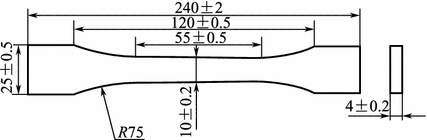
Cast resin tensile test specimen
In the test operation, the test load application rate is 10 ± 0.5 mm/min for tensile strength determinations and 2 mm/min or handle operation for tensile modulus determinations.
Standard GB/T 2568-1995 is a test method to determine resin casting tensile properties.
-
(2)
Small specimen test methods: To simplify specimen preparation and to save raw materials, small specimens can be used to determine the tensile properties of resin matrixes.
Specimen requirement: Since all composite resin matrixes are hard thermoplastic or thermosetting plastics, small specimens for their tensile property determinations are selected as the model I specimen, as specified in GB/T 16421-1996; typical specimen dimensions are shown in Fig. 3.3 and Table 3.4.
Fig. 3.3 
Small specimens for the cast resin tensile test
Table 3.4 Small specimen requirements for the cast resin tensile test/mm
-
(1)
-
(3)
Resin matrix compression test
The typical shape and dimensions of the resin matrix compression test specimen are shown in Fig. 3.4.
Fig. 3.4 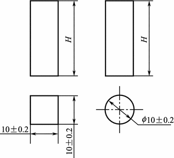
Shape and dimensions of the resin matrix compression testing specimen
The compression strength testing requires a specimen of height H = (25 ± 0.5) mm, and the compression modulus testing requires a specimen of height H = 40–60 mm. The specimen is a square section either of column type or of cylinder type. The top and bottom end surfaces need to be parallel and vertical to the axes, and the non-parallel dimension of the end surface should be less than 0.04 mm. Standard: GB/T 2569-1995 Compression testing method for cast resins.
-
(4)
Resin matrix shear test (open-hole method)
Principle: Use a cylinder hole puncher and apply a compression-type shear load onto the specimen to cause shear deformation or failure. This way the shear strength of the thermoplastic or the thermosetting plastics can be determined.
Requirements for the resin matrix shear testing specimen are given as follows:
-
(1)
Uniform thickness, smooth and clean surface, no machining damage or impurities.
-
(2)
Specimen is either a square plate with a side length of 50 mm or a circular plate with a diameter of 50 mm. The thickness is 1.0–1.25 mm and the central hole diameter is 11 mm. The standard specimen will be 3–4 mm thick, as shown in Fig. 3.5.
Fig. 3.5 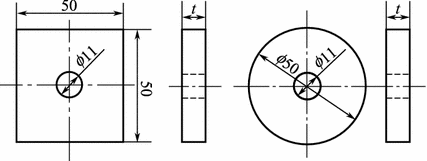
Shear test specimen
-
(3)
Specimen preparation.
Injection molding, press molding, extrusion or machining can be used to prepare the specimen, but the test results obtained using different methods cannot be compared with each other.
Standard: GB/T 15598-1995 The shear test method for plastics.
-
(1)
-
(5)
Resin matrix bending test
The specimen for the resin matrix bending test is a rectangular column with the dimensions shown in Fig. 3.6.
Fig. 3.6 
The bending test specimen
Test method: Three-point bending with a span of 100 mm, the loading head radius of 5 ± 0.1 mm and the specimen support top half-sphere radius of 5 ± 0.2 mm.
Standard: GB/T 2570-1995 The bending test method for casting resins.
-
(6)
Resin matrix impact testing
Principle: Use a simple support beam pendulum impact tester to measure the resin matrix impact strength and to evaluate the resin matrix toughness.
Specimen requirement: The specimen should include a notched and an un-notched impact specimen. For thermoplastic or tougher thermosetting resins, the notched specimen will be used while the un-notched specimen should be used for lower toughness thermosetting resins. The specimen dimension requirements are shown in Fig. 3.7.
Fig. 3.7 
The casting resin impact test specimen
The simple support beam span is 70 mm when the pendulum impacts the center of the specimen and the impact speed should be 2.9 m/s. For notched impacting testing, when failure occurs in non-notched area, the test results are not valid, and a compensation test is necessary. For an un-notched specimen, when fracture occurs beyond 1/3 of the span from the central line, the testing results are not acceptable, and a compensation test is needed. Standard: GB/T 2571-1995 The impact test method for casting resins.


3.3 High-Performance Phenolic Resin Matrixes
Phenolic resins are prepared by condensing phenyl and aldehyde compounds. Among them, the most important phenolic resins are condensed phenols and methyl aldehyde. Among the condensed plastics, phenolic base plastics are the most widely applied and produced in the highest volume.
Phenolic resins are the earliest synthesized polymers [6]. In 1872, A. Bayer first discovered that phenol and aldehyde can interact and generate a resin-like product under acid catalysis. In 1910, Bachland submitted a patent on phenolic curing by “applied heat and pressure,” successfully establishing prepolymer curing technology. This is condensation under “applied heat and pressure.” He further pointed out that the thermoplastic characteristics of phenolic resins will depend on the ratio of phenyl to aldehyde, as well as the catalyst. He also indicated that wood powder and other fillers can improve resin brittleness and thus industrial production and other applications were realized. In 1911, Aylesworth discovered that phenolic resins could be cured by adding hex-functional tetramine. In 1913, a German chemist K. Albert discovered a manufacturing method for oil-soluble phenolic resins, which advanced synthetic resin coating industrial applications.
It has been more than 80 years since the initial use of phenolic resins and their plastics as raw materials. They are abundant, are of low cost and have good performance that meets the requirements of hi-tech fields such as the aerospace, electronics and automobile industries. Much innovative work has been carried out by researchers and engineers to exploit the potential and increase the performance of phenolic resins. Many new materials have been developed. In this chapter, modern achievements in phenolic resins will be discussed.
3.3.1 The Synthesis of Phenolic Resins
3.3.1.1 Linear Phenolic Resins
The synthesis of phenolic resins should be carried out at pH values less than 3.0. Phenolic resins are prepared by the condensation of methyl aldehyde and trifunctional (phenol, resorcin) or difunctional (orthocresol, paracresol, 2,3-dimethyl phenol, etc.) phenols. For trifunctional phenols, the quantity of phenol must be in excess (mol ratio of phenol to aldehyde of 6:5 or 7:6) as less phenol could result in thermosetting resins. An increase in phenol could decrease the relative molecular weight of resins, as shown in Fig. 3.8. The linear phenolic resins prepared by acid catalysis generally have a number average molecular weight of 500 with five phenol rings in the molecules. This is a mixture containing variable and dispersed compositions, as given in Table 3.5.

Correlation of relative molar mass to raw materials in linear phenolic resins
Because unreacted species are present in the phenol core, thermosetting resins could result upon methyl aldehyde or hexamethylenetetramine reactions and can further condense into infusible and insoluble bulk products.
3.3.1.2 Thermosetting Resins
Thermosetting phenolic resins are produced by the condensation of phenol and methyl aldehyde (overloaded) under alkali or acid media, and they are referred to as fusible thermosetting resins [7]. For condensations in alkali medium, the mol ratio of phenol to aldehyde is usually 6:7 (pH = 8–11). If the amount of methyl aldehyde is increased, hydroxymethyls will be present in the resin systems. Therefore, thermosetting phenolic resins can self-heat to form infusible and insoluble cured products.
In addition, the hydroxyphenol produced by the additive reaction between phenol and aldehyde in stable alkali medium has been found to be stable. Therefore, 2-hydroxy methyl phenol or 3-hydroxy methyl phenol can be obtained using any mol ratio, as given in Table 3.6. By increasing the reaction temperature or extending the reaction time, they can be further condensed into solid resins; even with insufficient aldehyde, they can produce thermosetting resins.
At this point, a part of the phenol will be dissolved in the resin and exist in “free phenol” states. Under alkali catalysis, it will only be possible to form thermosetting resins, which is independent of the phenol to methyl aldehyde mol ratio. However, the mol ratio will affect the cure rate of the phenolic thermosetting resins, as shown in Fig. 3.9. With an increase in methyl aldehyde, the resin viscosity will decrease and the cure time will decrease.

The mol ratio of phenol to methyl aldehyde versus the resin viscosity and cure time (viscosity measured at 25 °C). 1—Cure time; 2—Viscosity
3.3.1.3 Innovation in Phenolic Resin Synthesis
Although there have been no major advances in phenolic resin synthesis recently, much work has been done on the current processing techniques and raw materials. Some innovative progress and breakthroughs have been reported [8, 9]. For example, the new suspension process changes in reaction media, increases the molecular mass in phenolic resins and changes in the reactants of the prepolymers of phenolic resins.
-
(1)
New synthetic processes
Currently, the features of phenolic resin synthesis are a large-scale reaction pot, computerized process control, continuity in product output and cooling and the suspension method for the synthesis of granular phenolic resins [10, 11]. For the suspension method, the synthetic procedures include: suspension polymerization → solid and liquid separation → drying → products. In comparison with traditional processes, the suspension method consumes less energy and has processing continuity, grain uniformity, low free phenol content in the end products and superior quality. In China, research into the suspension method has been carried out recently [12], and suspension processing techniques to produce fusible phenolic resins have been successfully developed [13]. The products conform to the technical standards of phenol-amine-modified phenolic resins.
-
(2)
Linear phenolic resins with high relative molar mass
Phenolic resins were generally prepared by phenol and aldehyde reactions in water containing an alkali (NaOH, KOH or ammonia water) or acid (oxalic acid, hydrochloric acid) as catalysts. The relative molar mass was lower because of product branching and heterogeneity. To increase the molecular weight of phenolic resins, many studies have been carried out and linear phenolic resins with high molar weight were obtained when using a strong acid in highly polar solutions. o-Cresol or p-cresol was reacted with methyl aldehyde, and the basic properties of the resins are given in Table 3.7 [14]. Table 3.8 lists data characterizing the performance of the cured products obtained by the reaction of these linear phenolic resins and diglycidyl ethers of bisphenol A in equivalent mixtures. Phenol and methyl aldehyde were used as reactants (mol ratio 1:1), acetic as the reaction medium and hydrochloric acid as the catalyst. Phenolic resins with a very high relative molar mass can be prepared with (M n) values up to 63,600 and a M w/M n of 6.21. Another method is to use a metal or P, S nonmetal catalysis to replace the traditional alkali or acid catalysis to generate phenolic resins [15].
Table 3.7 Performance of high molar mass phenolic resins Table 3.8 Performance of cured products Results indicate that when Mg, Ca, Cu and Zn were used as catalysts, the reaction time was shortened and activation increased, while P, Fe, Al, and Ni as catalysts will result in longer reaction times and lower activation. However, both can generate high molecular mass phenolic resins. If oxalic acid is used together with Al, the system does not gel, even if too much methyl aldehyde is added. Using these catalysts to catalyze naphthol, phenol and methyl aldehyde co-condensed systems can produce phenolic resins with a high molar mass and naphthol content. This type of resin has very good thermal resistance.
Recently in Japan, a new phenolic resin with high molar weight has been developed. This resin can generate grains in water and can be used for injection molding without hexamethylenetetramine as a curing agent. Its starting weight loss temperature is 338 °C, its bending strength is 31.9 MPa, its impact strength is 11.0 kJ·m−2, and its water absorption rate is 0.05%.
-
(3)
Prepolymers in phenolic resin synthesis
During the curing of phenolic resins, low molecular weight volatiles can escape and affect the processing performance. Therefore, it is of great significance to prepare phenolic resins that will retain low molecular weight volatiles during the curing process [16,17,18]. In the early 1950s in the USA, GE used allyl chloride to prepare oxide-allyls and carbon-allyls on aromatic rings and in phenolic resins. Curing at high temperature and upon catalysis by an inorganic acid [19] is another way to use an unsaturated carboxylic halide ester liner phenolic resin low molecular weight polymer together with dilution and initiating agents to enable cross-linking and curing. Recently in Japan, phenolic resin low molecular weight polymers containing maleimide (synthesis in Fig. 3.10) were developed. The results have indicated good processing abilities, heat resistance and mechanical properties, which bodes well for this application’s future [19].
Fig. 3.10 
Synthesis of phenolic resins containing maleimide
-
(4)
Benzoxazine compounds
Benzoxazine compounds are new ring-opening polymerized phenolic resins that have been receiving plenty of attention. They have the advantages of ring-opening polymerization including: retaining low molecular weight volatiles during curing, low viscosity of the uncured small monomers and lower curing stresses. They will become a new phenolic resin product with wide applications in future. Details about their synthesis and performance will be discussed in Sect. 3.2.

3.3.2 Phenolic Resin Curing
Curing is a chemical process in which linear molecular structures are transformed into bulk structures. These chemical reactions are usually complete by the part forming process. Therefore, the curing of phenolic resins will greatly affect part processing and performance.
3.3.2.1 The Curing of Thermosetting Phenolic Resins
Thermosetting phenolic resins are prepared by the reaction of excess methyl aldehyde and phenols under alkali catalysis. The reaction mixture contains a large amount of reactable hydroxyl methyls. Curing can be conducted at high temperature and also low temperature when using an acid.
Curing reactions under applied heat in thermosetting phenolic resins are very complex because of the temperatures applied and also the raw material chemical compositions and catalysts. Research has shown that hydroxymethyl condensation will mainly generate methine bonds and ether bonds. Low molecular weight water is released at temperatures lower than 170 °C [13]. When the temperature is increased from 170 to 200 °C or higher, a more complex second-phase reaction will occur in the resins. This is basically the decomposition of dibenzyl ether and the escape of a small quantity of methyl aldehyde. Almost no water is generated. Pressure is needed for the curing of thermosetting phenolic resins (laminating 10–12 MPa, molding 30–50 MPa). The purpose is to avoid the escape of low molecular weight volatiles (solutions, water and activated methyl aldehyde generated during thermal curing) as this will cause voids and increase flowability.
Thermal setting phenolic resins can be also cured by adding appropriate inorganic or organic acids such as hydrochloric, phosphoric, sulfuric, dichloride p-toluene sulfonic acid and mahogany acid. The basic reaction during curing will be the formation of methine ether bonds. Other features include a strong reaction and a large amount of heat release. Acid-cured thermosetting phenolic resins are used as castings or adhesives and also in flame-retardant composite applications. Details are given in Sect. 3.2.
3.3.2.2 Linear Phenolic Resin Curing and Curing Agents
Linear phenolic resins are stable and require curing agents for curing into bulk structures. Commonly hexamethylenetetramine and paraformaldehyde are used as curing agents, and the curing agents in industry include trimethylol, polymethylol melamine resins, polymethylol bimeric cyanamide and epoxy resins. Hexamethylenetetramine curing agents have many advantages: fast curing speed, short press molding time, good stiffness of cured parts at high temperature and minimum buckling after release from molds. Different curing agents can be used for other applications.
To produce high-performance phenolic resin materials, new curing agents have been developed and applied. Oxazoline compounds are used to cure phenolic resins and give cured parts with increased toughness without a loss in flame retardant, low smoke and high thermal resistance. In Japan, research in this field is actively carried out and some reports on the oxazoline curing of polyamide have been published. Culbertson et al. have used phenylene bioxazoline (PBOX) as curing agents and have developed a series of phenolic resins using 1,3-PBOX as a curing agent. They prepared linear phenolic resins with a low free phenol content using dilution methods for processing to prepare high-performance composites (Fig. 3.11).

Molecular structure of 1,3-PBOX
Apart from PBOX, benzoxazine and bismaleimide (BMI) are special cross-linking agents. In Fig. 3.12, the effects of linear phenolic resin and benzoxazine content on gel time were evaluated by the plate knife method at 180 °C. When the phenolic resins were cured using benzoxazine, no low molar weight volatiles escape and the end parts have a light color. Figure 3.13 shows typical molar structures of benzoxazine compounds.

Effect of linear phenolic resin and benzoxazine content on gel time

Typical molar structure of benzoxazine compounds
Since the hydroxyl and the activated hydrogen on the phenol core (p or o-hydroxyls) can give additive reactions with the bi-bonds in BMI, the BMI can also be used as a cross-linking agent for phenolic resins. No volatiles are released during curing, and the cross-linking reaction proceeds very quickly at higher than 150 °C. Reports indicate that the starting weight loss temperature of the cured parts of linear phenolic resins and BMI is higher than 400 °C, and the bending strength at 220 °C can be 75%. The low molecular weight polymers have very good shelf stability.
3.3.3 Modification of Phenolic Resins
Phenolic resins have a good adhering ability, and the cured parts have high thermal resistance and good dielectric properties. Phenolic composites have excellent mechanical properties, and glass and phenolic composites have bending strengths up to 110–150 MPa. Conversely, phenolic resins have structural drawbacks that should be improved. The main drawbacks of phenolic resins are that the hydroxyl and phenol groups in the molecular structures are very easily oxidized and this will affect the thermal and oxidation resistance; the cured resins will be brittle because methylene linkages are only found between the phenol cores. Therefore, it is necessary to enhance their toughness. Hydroxyl and phenol groups absorb moisture easily, which will affect the electric and mechanical performance and alkali resistance of cured parts. The medium or high pressures used for processing will also limit the application as resin matrixes are required in high-performance composites. Therefore, phenolic resins need to be improved in terms of thermal resistance, toughness and processing performance.
3.3.3.1 Toughening of the Phenolic Resins
Increasing the toughness of phenolic resins can be done in three ways: ① adding tough materials such as natural rubbers, nitrile-butadiene rubber (NBR) or styrene-butadiene rubber (SBR); ② adding an internal tough substance like a modified phenolic resin; ③ using reinforcements like wood powder, glass fiber or fabrics, plasma or cotton to improve brittleness.
-
(1)
External toughening of phenolic resins
Research on the rubber toughening of phenolic resins has been reported since early times. Rubbers are a kind of elastomer that can improve the brittleness and adhering ability of phenolic resins; however, to achieve optimum improvement, the chemical reaction between the rubber and the resin must form primary bonds. However, this will result in a loss of other properties of the phenolic resins. In the rubber toughening of phenolic resins, a certain quantity of elastic latex is added at any stage to phenol to give a distribution of grain size in 0.01–0.1 μm. In two-phase structures, the phenolic resins prepared this way have higher toughness without any apparent decrease in thermal resistance, bending strength, fracture elongation rate or hardness. Another toughening method is to add a conjugated diene glue solution containing positive-ion activation agents during dehydration in fusible phenolic resins, and to disperse the phenolic resins to give grain sizes less than 10 μm, two-phase structures are formed. Using thermoplastic resin mixtures with solvent parameters of 7–15 and with good compatibility is another toughening method. Some parameters are given in Table 3.9. In Table 3.10, the mechanical properties of mixtures blended with polybutylene terephthalate (PBT), polyamide, polyphenyl ether, etc. and melted phenolic resins are given.
Table 3.9 Mechanical performance of thermoplastic resin-toughened phenolic resins Table 3.10 Mechanical performance of toughened phenolic resins -
(2)
Internal toughening of phenolic resins
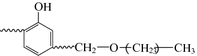
Polyvinyl acetaldehyde improved phenolic resin is a modified phenolic resin applied in industry since early times, as shown in Fig. 3.14. Polyvinyl acetaldehyde can improve the brittleness of phenolic resins, increase their adhering ability and strength and decrease their curing speed and the processing pressure. However, the longer aliphatic chain introduced into the phenolic resin bulk structure can affect the thermal resistance.
Fig. 3.14 
Polyvinyl acetaldehyde improved phenolic resin
The polyvinyl acetaldehyde improvement comes from the dehydration reactions of the hydroxyl groups with methylol in the phenolic resins, and this forms a block copolymer or a branched copolymer.
To reduce the thermal resistance loss, a higher thermal resistance polyvinyl acetaldehyde is often used with a certain ratio of organic silicon monomer. A typical formulation is given as follows:
- Methyl-order phenolic resin:
-
135 (mass ratio)
- Polyvinyl acetaldehyde:
-
100 (mass ratio)
- Orthosilicon ethyl:
-
30 (mass ratio)
Upon blending with fusible linear phenolic resins, NBR containing carboxyls is added because the methylol in the fusible linear phenolic resins can react with divinyl butadiene bonds or with the carboxyls in NBR giving strong bonds between the phenolic resins and NBR. Therefore, the bending and tensile strengths are increased, as are the impact strength and the fracture elongation. Table 3.11 lists some properties of the cured parts of the phenolic resins toughened by NBR or carboxyl NBR.
Table 3.11 Properties of phenolic resins toughened by NBR or carboxyl NBR (CTNN) The use of ethylene glycol to dissolve phenolic resins and blended polyurethane oligopolymers has been reported. Linear phenolic resins were blended and cured with liquid butadiene containing an epoxy group, hexamethylenetetramine and free groups, which gave high impact strength phenolic resins.
Another common toughening method is the use of ether alcohol phenol and the hydroxyl in aldehyde prepolymers, for example:
This is because they can form hydroxyl benzyl positive ions. A high hydroxyl phenol content and excess alcohol can avoid self-condensation.
The above reactions are commonly carried out at pH 5–7 at 100–120 °C using methyl alcohol, butyl and isobutyl alcohol. Butyl alcohol is most commonly used. The generated water is separated upon co-boiling with excess butyl alcohol. The etherized methyl-order phenolic resins can be far more soluble in aromatic solvents.


3.3.3.2 The Structural Modification of Phenolic Resins and New Products

Boron phenolic resins have much better thermal resistance, an instant anti-high-temperature ability and better mechanical properties than phenolic resins [5].
Prepolymers can be transformed into molding compounds by hexamethylenetetramine and some filler, and cured at high temperature (200 °C) to obtain the required high thermal resistance. If hexamethylenetetramine is replaced by epoxy compounds, the curing reaction can take place at lower temperature (100–120 °C). Since the hydrogen in the hydroxyl phenol is substituted by boron, its waterproof properties are improved. The more flexible –B–O– bond is incorporated into the molecules resulting in an increase in brittleness and strength because of the 3D cross-linking structure of the cured products. Their anti-ablating and quantum resistance are higher than those of common phenolic resins.
Boron-modified paraaminebenzylic aldehyde resins are kind of very high anti-ablating material. They are prepared by adding 3 mol of paraaminephenyl and 1 mol of boron acid into boiling dimethylphenyl. Water can be evaporated as a co-boiled compound. Triparaamine–boron compounds can be dissolved in water and are blue. Furthermore, a trialdehyde (or aldehyde water solution) upon reaction for 3 h at 70 °C under acid catalysis conditions yields a red solid resin that can be cured by hexamethylenetetramine. This resin shows a small weight loss under very high temperatures or stresses and can yield a nitrogen compound similar to boron at temperatures higher than 2500 °C.
Typical bisphenol A boron phenolic resins are not affected by the drawbacks of a decrease in dielectric property under wet conditions, which would happen because of the phenol in aldehyde boron phenolic resins. It can thus be widely used in rockets, missiles and space vehicles as a superior ablating material [20]. Its synthesis comprises two steps: First NaOH is catalyzed to generate the additive and a condensation reaction between bisphenol A and an aldehyde with proper dehydrate and then boronic acid or boron sand is added for further reaction and dewatering occurs under vacuum to give thermosetting phenolic resins. In Table 3.12, the properties of glass and boron phenolic resin laminates and fiber composites are given.
-
(1)
Mo acid-modified phenolic resins [ 21, 22 ]
The Mo acid-modified phenolic resin is a new resin with ablating features and can be used in ablating, thermal isolation, smoke removal and flame arresting, for example, its high silicon-oxygen glass cloth (fiber) composites can be used to make jet pipes in missile engines, fire guide tubes and their isolating liner materials.
The synthesis of Mo-phenolic resins comprises a chemical reaction wherein the intermediate molybdenum is chemically incorporated into the backbone of the phenolic resin. Using Mo oxidations, chloride and its acids can be used to react a phenol and an aldehyde to yield phenolic resins containing Mo. In general, Mo-phenolic resins require a two-step reaction:
-
①
Under catalysis, Mo acid and phenol will react to form an atomic linkage between Mo atoms and the oxygen atoms in phenol.

-
②
Further additive and condensation reactions will take place between the Mo acid phenol ester and an aldehyde to yield Mo-phenolic resins.

-
①
-
(2)
Phosphorous-modified phenolic resins
Phosphorous-modified phenolic resins can be prepared by phosphoric acid esterification or by a phosphorous oxychloride reaction. A bifunctional phosphorous oxychloride reaction is shown in Fig. 3.15 and will take place at 20–60 °C for the bioxazole alkyl group. Phosphorous-modified phenolic resins show superior thermal resistance and are flame proof under oxidation conditions, but they are not readily available presently.
Fig. 3.15 
Synthesis of phosphorous-modified phenolic resins
-
(3)
Heavy metal-modified phenolic resins
Phenolic resins can react with metal halides (Mo trichloride, Ti tetrachloride, W hexachloride) and metal alcoholates (acetylacetone compounds) to obtain thermal resistance and flame arresting resins. The phenolic resins containing metals can have a far slower decomposition speed at high temperature. In general, the metal can yield metal carbon compounds with carbon atoms in the resins. These resins are colored and possibly contain 20% ion-bonded metals.
Under acid catalysis, a reaction will take place to give ether aromatic-hydride aldehyde resins similar to linear phenolic resins. The addition of powder or fiber fillers together with a curing agent such as hexamethylenetetramine, a promoter such as MnO2 or CaO2 as well as pigment and release agents into the resins and then mixing, rolling and grinding into molding compounds gives resins suitable for press molding, transfer molding and injection or casting processes.
These molding compounds have high mechanical strength, low water absorption, high electric resistance and dielectric strength as well as stability toward acid and alkali. They can be used over long periods at 200–220 °C in the military, transportation and electricity industries.
Under alkali catalysis, ether aromatic hydrides will react with aldehydes to generate thermosetting resins, which can be used to impregnate glass fibers or fabrics. Usually, these resins are supplied as commercial methylethyl ketone solutions with a solids content of 50–60%.
Aromatic-hydride aldehyde resins need 150–180 °C and 8–28 MPa for curing and are post-cured at 170 °C for 4–6 h to further increase performance. Post-curing at 170–250 °C for 12 h will be necessary. The glass composites made from these types of resins have a higher retention rate and bending strength after aging at 250 °C for 1000 h. The bending strength is still more than 80% after exposure to 275 °C for 750–1000 h, and at 300 °C for 300 h the bending strength is more than 50%. Therefore, aromatic-hydride aldehyde resins are good high-temperature-resistant materials and are used in rocket shells and in engine main body materials.
-
(4)
Organic silicon-modified phenolic resins [ 23 ]
Organic silicon-modified phenolic resins have been used for decades because of their superior thermal and moisture resistances, but they have a low mechanical strength. Modification will mainly increase the heat resistance and waterproof characteristics. Organic silicon-modified phenolic resins undergo the typical reaction shown in Fig. 3.16.
Fig. 3.16 
Typical reaction of organic silicon-modified phenolic resins
To simplify modification processes in industry, impregnation, drying and thermal compression are commonly used. If ethyl silicate is used to modify glass or phenolic resin composites, 100 units of amine-catalyzed phenolic resin, 32 units of ethyl silicate and water diluted into a glue solution with a 55–60% solids content are used and impregnation occurs on vertical machine at 90–95 °C. After drying, press molding into high-temperature glass cloth, lamination is carried out for aero applications. It is a very good ablating material and has a long service life at 200–300 °C. It has largely been used in rockets, missiles and spacecraft. Phenolic resins can also be modified by phenol silicon monomers or aromatic silicon hydrides, which can be used to impregnate glass fibers or cloths, in addition to plasma or carbon fiber fabrics to make structural materials or heat-proof, electric isolation and ablating materials.
In organic silicon-modified phenolic resins, the phenolic resins are generally subjected to allylation and then an additive reaction with organic polymers, as shown in Fig. 3.17.
Fig. 3.17 
Organic silicon-modified phenolic resins
-
(5)
Ether aromatic-hydride-modified phenolic resins
For the synthesis of phenolic resins, phenyl hydroxide will not normally take part in the reaction. Therefore, the resistance toward alkali, solution and thermal oxidation is affected. To overcome these drawbacks in the phenolic resin structure, aromatics or aromatic hydrides can be incorporated to protect the phenyl hydroxide and can then be reacted with an aldehyde to yield phenolic resins. This kind of resin has good alkali resistance, low moisture absorption and high mechanical strength in addition to superior thermal and oxidation resistance. They can be used over long periods at 180–200 °C.
Ether aromatic-hydride aldehyde resins are prepared by the dichloride-methylation of aromatic hydrides and then methanol-etherized in an ether exchange reaction with phenol under Fourier catalysis to form aramid ether compounds containing two phenol rings. The reaction with an aldehyde to generate the ether aromatic-hydride aldehyde resin is shown in Fig. 3.18.
Fig. 3.18 
The synthesis of ether aromatic-hydride aldehyde resins
Phenol and Mo acid are added into the reaction vessel and stirred upon heating at 60 °C. Stirring is maintained for 30 min, and a 37% aldehyde water solution is added upon proper catalysis. Stirring is continued upon heating. The isothermal reaction continues for 2 h, and then the water is removed from the resin under vacuum to yield a dark green Mo-phenolic resin. After cooling, a green solid is obtained. This Mo-phenolic resin can be dissolved in alcohol and acetone, showing bright purple without any suspensions. The resin can be cured by hexamethylenetetramine, which is commonly used in linear phenolic resin curing.
Mo-phenolic resins are new ablating resins (see Table 3.13 for properties). As the Mo content in the resins is increased, the decomposition temperature increases (Table 3.14). Mo-phenolic resins are cured at 150–160 °C and decompose at 460–560 °C. A thermal weight loss of 40% occurs at 700 °C, while B-phenolic resins have a weight loss of more than 50% at 700 °C. As the Mo content in the phenolic resins is increased, the thermal resistance will increase. Glass fiber composites made from this resin have the ability to resist ablating and erosion, and they also possess high mechanical strength and good processing performance. They can be used to make ablating and thermal materials for rockets and missiles.
Table 3.13 Properties of Mo-phenolic resins Table 3.14 Thermal properties of Mo-phenolic resins with varied Mo content -
(6)
Dimethylbenzene-modified phenolic resins
Since phenolic resins have hydrophilic phenol groups that easily absorb moisture and have no resistance to oxidation, they possess poor electric properties and thermal resistance. Dimethylbenzene-modified phenolic resins (also referred to as phenol-modified dimethylbenzene aldehyde resins) have been developed. Its synthesis includes the use of dimethylbenzene and an aldehyde to synthesize dimethylbenzene aldehyde resins under acid catalysis. A further reaction is carried out between a phenol and an aldehyde.
-
(1)
Synthesis of dimethylbenzene aldehyde resins: Sulfuric acid, phosphoric acid, hydrofluoric acid and aluminum trichlorides are used as industrial catalysts. The reaction between m-xylene and an aldehyde will take place as shown in Fig. 3.19.
Fig. 3.19 
Reaction between dimethylbenzenes and aldehydes
Industrial dimethylbenzenes have a relative molar mass of 250–700, and compounds I–IV containing 3–6 dimethylbenzene rings are shown in Fig. 3.19.
With excess dimethylbenzene and a high concentration of sulfuric acid (catalyst), the reaction will mainly give compound I. When the aldehyde is in excess, and the catalyst has a low concentration, compound III will be dominant.
-
(2)
Phenol-modified dimethylbenzene aldehyde resins: Modified dimethylbenzene aldehyde resins are formally similar to thermoplastic phenolic resins but cannot be cured with hexamethylenetetramine, and only their relative molar mass is increased. If they further react with a phenol and an aldehyde, thermosetting phenolic resins are generated as shown by the reactions in Fig. 3.20.
Fig. 3.20 
Synthesis of dimethylbenzene-modified aldehyde resins
Industrialized phenol-modified dimethylbenzene aldehyde resins have superior performance and have been used in glass laminates, glass laminated pipes and glass fiber composites.
In Table 3.15, the properties of glass cloth laminates made using phenol-modified dimethyl-benzene aldehyde resins are listed. These laminates were tested at 200 °C for 400 h or 250 °C for 24 h, as well as being subjected to X-ray radiation of 103–109 R, and no changes in their bending property were found. Additionally, they are resistant to acid, alkali and organic solutions.
Table 3.15 Properties of glass cloth laminates made using phenol-modified dimethylbenzene aldehyde resins Dimethylbenzene aldehyde resins are of industrial interest for press molding. Their preparation is similar to that of linear phenolic resins: Phenol and dimethylbenzene are blended in an appropriate ratio and then reacted with aldehyde under acid catalysis, which yields a fusible and soluble A-stage solid resin. The product is obtained after grinding, mixing with hexamethylenetetramine and adding fillers, pigments and release agents. The plastic parts produced by the plastic machine-milled press molding powder have high thermal resistance, good surface finishing and good dielectric properties after wetting and can be used for injection and casting. The main disadvantage is a slow cure speed and the need for further improvements.
-
(1)
-
(7)
Phenol salicylaldehyde phenolic resins
Phenol salicylaldehyde phenolic resins are prepared by the reaction between phenol and salicylaldehyde as follows:

The preparation of phenol salicylaldehyde phenolic resins is done using excess phenol in the reaction with salicylaldehyde under acid catalysis conditions and dehydration at 160–180 °C. Because of the many phenol rings in their molecular structure, these resins have high thermal resistance and good storage stability.
In Table 3.16, the properties of the cured products of mixtures of phenol salicylaldehyde phenolic resins, diaminodiphenylmethane and bismaleimide (BMI) are compared with BMI cured by diaminodiphenylmethane, and their thermal resistance, mechanical performance and storage stabilities are very good.
Table 3.16 Properties of phenol salicylal phenolic resin-cured bismaleimide resins -
(8)
Phenol-triazine (PT) resins [ 24 ]
Phenol-triazine (PT) resins are a kind of modified phenolic resin with good thermal resistance. They have good processing performance similar to those in epoxy resins, and a high-temperature resistance ability similar to bismaleimide (BMI) as well as excellent flame-retardant properties similar to that of phenolic resins. A typical synthesis is shown in Fig. 3.21.
Fig. 3.21 
Synthesis of PT resins
PT resins are a new matrix system that can be used in high-performance composites. It is a self-curing system with advantages like a low shrinkage rate, retention of volatiles, a glass transition temperature higher than 300 °C and an elongation limit of up to 3.5%. Their main drawback is that the raw materials used for resin synthesis are toxic and require by-product recycling, which is environmentally unfriendly. Therefore, industrial-scale production still requires further research. In Tables 3.17 and 3.18, some PT resin composite performance data are presented.
Table 3.17 Bending test results of unaged unidirectional CF/PT laminates Table 3.18 Bending test results of unidirectional CF/PT laminates aged at 260 °C for 600 h The phenolic resins synthesized by the condensation of phenols, aromatic amines and aldehydes can react with aromatic hydroxyl–anhydrides to give modified phenolic resins containing imide groups. It is a new phenolic resin with superior performance in terms of thermal resistance, curing behavior and storage stability. Typical reactions are shown in Fig. 3.22.
Fig. 3.22 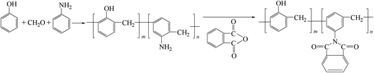
Synthesis of imide-containing phenolic resins
The hydroxyls and phenols in p-hydroxyl BMI are oxidized to form 4-phenoxyl maleimide, which are then further reacted with ether-diphenyl or polyaldehyde to generate BMI-modified ether-diphenyl-type phenol resins with excellent thermal resistance, impact toughness and hydrophobic properties (see Fig. 3.23 for synthesis) [25].
Fig. 3.23 
Synthesis of BMI-modified ether-diphenyl-type phenol resins(9) imide-containing phenolic resins
-
(9)
Benzoxazine compounds [ 5 ]
Benzoxazine compounds are a new kind of ring-opening polymerization phenol resin monomer. They can be used to produce polymers that are similar to phenolic resin structures upon ring-opening polymerization. Low molecular weight volatiles are retained during curing, and the products have a low void content and shrinkage rate. This can reduce internal stresses and microcracks. They exist as ring monomers with a low molar mass and viscosity, and they form composites easily. Since some phenols and hydroxyls are present in these resins, they have an improved thermal resistance. At high reaction temperatures, the phenols and hydroxyls convert into molar ether bonds, which increases their toughness. Therefore, they can be widely used in many areas as new types of phenolic resins.
-
(1)
Benzoxazine compounds are commonly referred as 2H-dihybro-1,3-benzoxazine and are synthesized as shown in Fig. 3.24.
Fig. 3.24 
Synthesis of dibenzoxazepine intermediate compounds
In 1973, Schreiber introduced benzoxazine compounds to polymer science for use in ring-opening polymerization. Much development has taken place in terms of the synthesis and applications of benzoxazine compounds. From the synthesis by Holly and Cope, by changing the reaction media and improving the synthesis processes, intermediate compounds were developed as shown in Fig. 3.24.
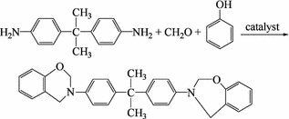
The following synthesis uses polyhydric phenol, phenol amine and an aldehyde as reactants to prepare intermediate products for polybenzoxazine:

Using diamine and phenol amine as reactants to prepare intermediate products for polybenzoxazine is done as follows:
Because the reactants can differ, and organic media or water can be used as reaction media for the preparation of suspensions, the obtained intermediate compounds will have different physical states. Therefore, wet or dry processing methods can be used to produce superior performance benzoxazine rings.
-
(2)
Structural characteristics of benzoxazine intermediate compounds Quantum chemistry calculations have indicated that benzoxazine intermediate compounds have odd-shaped chair structures (oxazine rings) and also that their electronic charges are non-uniformly distributed. The methylenes in the oxazine rings have positive charges, while the hetero atoms (N,O) have negative charges. Analyses have been carried out on the model benzoxazine compounds (3-phenol-6,8-dimethyl-3,4-2H-1,3-benzoxazine compounds, 3-phenol-6,8-2Cl-3,4-2H-1,3 benzoxazine compounds, 3-phenol-6-methyl-3,4-2H-1,3 benzoxazine compounds) and have indicated that the oxazine rings show an infrared characteristic absorption peak near 945 cm−1, while in H-NMR analysis, peaks are present near 4.7 × 10⁻⁶ and 5.3 × 10⁻⁶. These analyses are consistent with classic calculations.
-
(3)
The solubility of benzoxazine intermediate compounds As matrix resins, benzoxazine intermediate compounds require good solubility, apart from dry processing applications, as given in Table 3.19. Test results of intermediate solubility in different solvents are listed, indicating that a small difference exists between the intermediates and common phenolic resins. Oxazine rings are only slightly soluble in water-free alcohol.
Table 3.19 Solubility of intermediates Thermal ring polymerization under activated hydrogen: Intermediates contain imperfect points in closed rings within phenol-hydroxyl (activated H). The phenol cores contain activated H and ring-opening polymerization can take place. In Table 3.20, the curing temperature of the above-mentioned intermediates is listed (DTA analysis).
Table 3.20 Curing temperature of intermediates The cured products have superior thermal resistance and the indexes range from 230 to 270 °C (in nitrogen). The residual carbon rate is 60–70% (in nitrogen), and the mechanical properties and T g of their castings are given in Table 3.21.
Table 3.21 Properties of cured intermediates Apart from the thermal ring opening caused by the activation of H, intermediates be polymerized under ionic catalysis conditions when using intermediate compounds as matrix resins. Aluminum trichloride can be used as a catalyst for the production of automobile brake materials with good processing performance, stable high-temperature braking coefficients and high toughness. In Table 3.22, several properties of glass cloth laminates fabricated using benzoxazine intermediates with epoxy resins under tri-amine catalysis conditions are given and compared with glass/polyamine-bismaleimide (BMI) laminate standards (thermal resistance: H grade, compliance with HB/Z308-1997). Glass/benzoxazine intermediate laminates have outstanding high-temperature mechanical properties. The bending strength at 180 °C is 267 MPa, and the residual strength can be 50% or higher. The thermal resistance index is higher than 200 °C, and therefore, benzoxazine intermediates are suitable as 180 °C long-term exposure structural materials.
Table 3.22 Performance of glass/intermediate laminates
-
(1)


3.3.4 Progress in Phenolic Resin Composites and Processing Techniques
In the 1980s with the urgent demand for fire-retardant materials, a new generation of phenolic resin composite system was developed at large chemical companies including the US’s West Chemical Co., Dow Chemical Ltd., OCF Company, INDSPEC Co. and the UK’s Imperia Chemical Co. Compared with traditional phenolic resin composites, the new generation of phenolic resin composites has fire-retardant properties, a low amount of smoke release, low toxicity and outstanding mechanical properties. Their most favorable feature is their suitability for current composite processing techniques including SMC, BMC, XMC, DMC, HMC, RTM, SRTM, SRIM [26], filament winding (FW), pultrusion, spraying and handy laying.
3.3.4.1 Resin Processing Requirements
To suit the many composite processing techniques, a variety of new phenolic resins have been developed for use in different production processes. For traditional phenolic resins, the redesign of constituent materials in phenolic resins has been investigated to achieve good processing and mechanical performance. Table 3.23 shows a performance comparison between new and traditional phenolic resins.
The principles for the synthesis of new phenolic resins are: Resins should have a high molar mass to reduce the amount of condensed water during curing; redesigned molecules, the addition of unsaturated bonds or other functional groups to increase the reaction speed; the use of activated solutions to reduce volatiles; the use of composed catalysis to increase catalyst selection.
-
(1)
Acid curing systems: Acid curing systems are widely used in FRP processing techniques. The resins are synthesized under alkali catalysis conditions, and curing by aromatic carboxylic acid can be accelerated. These resins have good processing performance and electronic properties. The processing times can be reduced to those of thermoplastics. The manufactured parts have high thermal stiffness and a small buckling deformation. In the UK, acid curing phenolic resins with different viscosities are commercially available and a variety of curing agents can thus be selected. Thixotropy phenolic resins can especially be used for central vertical part surfaces using convenient processes. This is similar to polyester gel coating and can improve part surface quality by avoiding pinholes on the part surface. The only drawback is the limited selection of product colors.
-
(2)
Thermosetting phenolic resins have great potential. To increase reactivity, a highly ortho-synthesis should be adopted to obtain a 2–4 mol ratio O/P methylene in the phenol-hydroxyl. If necessary, polyaldehyde/resorcinol catalysis can be used to process FRP at lower reaction temperatures. In the USA, a general A-stage phenolic resin is used and blended with a modified phenolic, and then cured into dark brown products (different from the acid cured yellow/brown).
-
(3)
To improve the brittleness of phenolic resins, epoxy and isocyanic resins are most commonly blended with phenolic or thermosetting phenolic resins and then blended with thermoplastics for copolymerization.
3.3.4.2 Composite Processing Performance
Research and development into new phenolic resins have greatly advanced the processing technologies of phenolic resin matrix composites (FRP). Traditional filament winding, laminating and press molding processing were further improved. Convenient operation, spraying, pultrusion and SMC/BMC processes can also be used for phenolic composites. Therefore, the FRP products of the phenolic resins have been extensively developed.
In Table 3.24, a processing performance comparison between traditional and new phenolic resin FRP is given indicating the superior processing performance of the new phenolic resins.
3.3.4.3 Phenolic Resin Composite Applications [27]
Phenolic resins have been used with a variety of reinforcements to develop many innovative materials. Because of their low cost and acceptance as thermosetting engineering plastics or thermal resistance engineering plastics, phenolic resin matrix composites are widely applied in different fields.
Electric industries: isolating structural component touch switches and high pressure parts.
Transportation industries: automobile and train braking materials, wind tunnels for trains and subway trains, internal decorating panels, worktable top surfaces, front nose-shaped parts and integrated drive chambers. Internal decoration panels in ships and boats will be another large market.
Aerospace: Modified phenolic resin-impregnated paper, fabrics and Nomex honeycombs have been largely used in internal cabin fire-retardant and decorate composites, rocket nose cones and bottles, and engine jet pipes are also made of phenolic resin composites.
In general, phenolic matrix composites have great potential in civil and military applications.
3.4 High-Performance Epoxy Resin Matrixes
Epoxy resins are a kind of polymer containing two or more epoxy functional groups. Since the 1940s, they have been developed into a wide variety of thermosetting resins including glycidol amines, glycidol esters and aliphatic-ester epoxy resins. Because of their superior processing performance, mechanical and physical properties and low cost, epoxy resins have been extensively applied in the mechanical, electronic, aerospace, chemical, transportation and infrastructure industries as coating materials, adhesives and composite matrixes.
General purpose epoxy resins such as bisphenyl-A resins and their modified resins are cured by common curing agents but have some disadvantages like high moisture absorption, poor dimensional stability and poor dielectric properties as well as brittleness. These resins do not meet the much higher demands of epoxy resins in terms of performance such as thermal resistance, water absorption, dielectric property, impact toughness and curing behavior. Therefore, epoxy resin modification and the development of new types of resin are growing fast. The use of new curing agents for epoxy resins has been used to produce high-performance epoxy resins. In this chapter, highlights of the development of high-performance epoxy resins that are used as composite matrixes will be discussed.
3.4.1 Synthesis of Epoxy Resins
High-performance epoxy resins are prepared by the condensation of multiple activated H-containing compounds such as polyamines, polyalcohols or epoxy chloropropane under strong alkali (KOH, NaOH) conditions. In the synthesis of epoxy resins, the reaction between the epoxy groups and activated H will take place resulting in molar chain elongation. By controlling the mol ratio of epoxy chloropropane and the activated H compounds, and using the proper reaction conditions, resins with different molar masses can be synthesized. In the synthesis of low molar mass resins, excess epoxy chloropropane can be added and the epoxy equivalent can be determined by chemical titration, relative absorbing quantitative infrared spectroscopy and NMR. In the synthesis of epoxy resins, some side reactions will occur such as the hydrolysis or branching of end groups in epoxy chloropropane or the resins will affect the epoxy qualities and the performance of the cured products. Control standards for epoxy resins include epoxy values, inorganic chloride content, total chloride content, volatiles content, molar mass, the viscosity of the liquid resins and the softening temperature of the solid resins.
3.4.2 Curing of Epoxy Resins and Curing Agents
3.4.2.1 Curing Reaction
Epoxy resins contain extendable tri-rings, which easily undergo cross-linking reactions with various cross-linking agents. Curing properties depend on the epoxy resin structure and also the type and proportions of the curing agents used. The curing speed of epoxy systems is controlled by the type of curing agent and the quantity as well as the curing processing parameters. Epoxy values can also affect the curing speed. The positions of the epoxy groups will be the principal factor that affects the epoxy resin reaction activity.
Epoxy groups can be homopolymerized into polyether chains through the following three mechanisms: negative ion (Lewis alkali catalysis), positive ion (Lewis acid) and coordination polymerization [28]:
Negative ion:

Positive ion:

Coordination:

Organic alkali like tri-amine is typical Lewis alkali epoxy resin curing agents. The simplest Lewis acid positive-ion curing agents are BF3 complex compounds. Metal alkyl-oxidations can follow the coordination polymerization mechanism to cure epoxy resins. This research is actively being pursued and will hopefully result in practical applications.
The gradually additive reaction in epoxy resins is very critical in practical applications, and the reactions include [29]:
Activated H:

Acid anhydride

Isocyanate ester

Cyanate ester

Curing agent types include polyamines, polyalcohols, anhydrides and polyphenols. All these agents can be catalyzed by acid or alkali catalytic agents. The ratio of curing agents to epoxy resins determined the properties of the cured materials.
3.4.2.2 New Curing Agents
For high epoxy resin matrixes, diaminodiphenylsulfone (DDS) is the most commonly used curing agent. Epoxy/DDS systems have high thermal resistance (T g) but allow a high amount of absorption and give poor hot/wet performance. In addition, these systems are brittle because of their high cross-linking density. To improve their hot/wet performance and toughness, the following polyetherdiamine cure agents have been developed: bietherdisphenylaminesulfone (BDAS), bietherdiphenylamine oxide (BDAO), bietherdisphenylaminebisphenyl-A (BDAP) and bietherdisphenylamine-6F-bisphenyl-A (BDAF). Their structures are shown in Fig. 3.25 [30].

Chemical structures of DDS and polyetherdiamine curing agents
Cured 4-functional epoxy resins (TGDDM) upon curing by these agents have performances as listed in Table 3.25.
Since polyetherdiamine contains longer molecular chains and more flexible ether bonds than DDS, the resins cured by polyetherdiamine will possess increased toughness but their dry thermal resistance will be slightly lower. Furthermore, because of their lower moisture absorption, the effect of absorbed water will be mitigated. Therefore, the cured resins will have a higher thermal resistance than those cured by DDS.
The Shell Co. in the USA developed the ether-bond-free curing agents Epon HPT 1061 and 1062 with structures as follows. Because of the large quantity of carbon-hydrogen bonds, their water absorption rates are much smaller than that of DDS [31, 32].
Epon HPT 1061

Epon HPT 1062

Epon HPT 1071 and 1072 resins are produced with the 1061 and 1062 curing agents. Their dry thermal resistance (T g) is about 10 °C lower than that of DDS and is in the range of 241–250 °C, while their water absorption rates are only 1.4–1.6%.
3M has developed a variety of biamine compounds with a fluorine-containing backbone, and they are used in epoxy curing as thermal and moisture-resistant curing agents. These agents give superior high-temperature performance and have very small water absorption rates. Fluorine–amines have the following chemical structure [30]:

In Fig. 3.26, the performance of bisphenol A epoxy (DGEBA) and fluorine epoxy (DGEBF) upon curing by blended I and II amines is shown [33]. Curing agent I contains two secondary amines for chain extension. II is an epoxy resin curing agent, and as the cure agent II content is increased, T g also increases because the cross-linking density increases. When the cross-linking densities are equivalent, the cured DGEBF has a much higher T g than DGEBA (210 °C) because of the stiff fluorine structures. Despite the existence of a stiff suspended fluorine group, the cured DGEBF shows a slightly higher toughness than DGEBA. As the cross-linking density is decreased, both DGEBA and DGEBF showed higher toughness while T g did not significantly decrease.

Performance of the fluorine–amine-cured resins
The DGEBF cured by curing agents I or II or a mixture of these agents has a water absorption of only 2.2% at 100% relative humidity and at 95 °C, and this shows that the fluorine group is strongly hydrophobic. As the content of curing agent I increases and the molar chains elongate, both DGEBA and DGEBF show a notable decrease in water absorption.
3.4.3 Structures and Performance of Epoxy Resins
Epoxy resins are essentially blended molar compounds with different degrees of polymerization. Some molecules are possibly branched and the end groups should be chloride or alcohol groups so that the epoxy group content, the chloride content and the molar mass distribution in the epoxy resin will influence resin curing and the cured resin’s performance. Apart from the synthesis conditions, the performance of the epoxy resins mainly depends on the molecular structures.
The glycidyl groups in the epoxy resins are flexible chain segments, which can decrease the resin viscosity and increase the processing performance while also decreasing the thermal resistance. The main approaches to increasing the thermal and mechanical properties are lowering the molar mass and increasing the amount of functional groups to increase the cross-linking density and to stiffen the structures. On the other hand, the stiffened structures will result in decreased solubility and an increase in viscosity resulting in a decrease in processing ability.
3.4.3.1 Diglycidyl Ether Resins
Diglycidyl ether bisphenyl-A (DGEBA) is a most important epoxy resin with advantages of good flow ability, good mechanical properties and low cost but also lower thermal resistance (T g < 120 °C). Only special aromatic amine curing agents can be used to produce in high-performance composites. Biphenyl-containing thermally stable stiffened rings have been used for the synthesis of high-performance epoxy resins. Table 3.26 lists some high-performance epoxy resins with their molar structures and basic properties [34, 35]. The results indicate that stiff rings can significantly increase the thermal–oxidation stability of the resins. The general formula of diglycidyl ether is given as follows:

The α,α′-bi-(4-hydroxyl-benzol)-p-diisopropyl benzene-diglycidyl ether (DGEIB) is a colorless thick liquid with an epoxy equivalent of 240–255 g/mol. Its viscosity is higher than 2 Pa·s at 25 °C, and it can be used as the diluent in high-performance epoxy resins.
YX4000 is a Shell Co.-developed crystallized low-viscosity resin with a viscosity of about 0.02 Pa·s at 150 °C. The cured resin has low internal stresses and good heat resistance, and the resin cured by DDM has a T g of 206 °C.
Shell’s YX-7-cured resins have spiral ring structures, and a mechanical relaxation zone exists between 50 and 100 °C as determined by the dynamic viscosity–elastic method. This is a low-temperature relaxation (β relax) that is not found in bisphenyl-A epoxy resins, and this comes from the aromatic rings connected to the P/O spiral rings. Because of this relaxation, its tensile strength and fracture elongation are double that of the corresponding epoxy resins.
Bisphenyl-S diglycidyl ether (DGEBS) is an epoxy resin containing a bisphenyl-S backbone with a low linear expansion coefficient. The reason for this is that the sulfuryls within the additives interact and hydrogen bonds form between the sulfuryl and hydroxyl group. This confines any sliding motion between the molecules. The commercial available resins of this type are the EXA 4023 resins supplied in Japan by the Printing Ink Chemical Industry Ltd.
Lo was the first to prepare phenolphthalein epoxy resins (DGEPP) [36], and they predicted that four possible structures exist for these synthesized resins, based on a balanced reaction between phenolphthalein and NaOH. Because of their yellow color and an IR absorption shift of phthalidyl (1725–1780 cm−1), the quinone structures were initially thought to be the main component in these resins, but Lin and Pearce discovered that only a basic structure, orthophthalate, was present in the DGEOO resin based on HPLC, IR, UV and NMR results. Pure phenolphthalein diglycidyl ether extracted by HPLC is a white thick resin with a soft point at 15 °C. Because of the long molecular chains and the increase in relative molar mass, the yellow color comes from the interaction between the secondary hydroxyl and the phthalate and this is initiated through H bonds.
Korshak was the first to prepare 9,9-bi(4-hydroxyl-benzol)-p-fluorine-diglycidyl ether (DGEBF) and discovered that this resin can be transformed into a very stable thermal–oxidation material after curing by benzene-hex-carboxylic-tri-anhydride. Lin and Pearce created a processing technique to produce crystalline DGEBA with a melting point of 132 °C [37]. The monomers can be melted after quick cooling, and they have a softening temperature of 38 °C on a DSC curve. The softening and melting temperatures of DGEBF depend on resin crystallization and molar mass. Since the introduced fluorine structures give increased stiffness, this epoxy resin will have a higher thermal resistance than traditional DGEBA epoxy resins. Table 3.27 shows the properties of these fluorine-containing epoxy resins cured at 175 °C for 4 h and post-cured for 2 h at 225 °C. If cured by DDS, these resins will have a higher T g (>187 °C) and stiffness (modulus > 2.9 MPa). Bi (o-replaced 4-hydroxyl-benzol)-fluorine-diglycidyl ether (DGEBF-DiMe and DiCl) has a higher T g and modulus than DGEBF [38].
Fluorine epoxy resins can be used in coatings and composite matrixes because of decreased water absorption. However, their high prices are the main obstacle for application.
3.4.3.2 Poly-Glycidyl Ether Resins
The purpose of polyfunctional group epoxy resin development is to increase heat resistance. In Table 3.28, some polyfunctional group glycidyl epoxy resins are listed [31, 32].
Compared with traditional epoxy resins, bisphenol A phenolic-type epoxy resins give higher thermal resistance cured products, and the T g can reach 224 °C when cured by DDS. They also have a good balance of properties. The available resins are supplied by Shell Epoxy Co. and Japan Printing Ink Chemical Ltd. The epoxy equivalent is 201 g/mol, and the melting point is 65 °C.
The naphthol-ring backbone-containing epoxy resins have good thermal resistance because of the hydrophobic naphthol-ring backbone, and they also have low melting viscosity, low water absorption and an excellent adhering ability. Curing by DDS gives resins with a T g as high as 300 °C.
Bi-cyclopentadiene epoxy resins, because of introduced cyclopentadiene in the backbone, are multifunctional epoxy resins with well-known toughness.
Tri-glycidyl ether epoxy resins, compared with phenolic-epoxy, have the advantages of narrow molar mass distribution and low melting viscosity.
1,3,5-Tri-(hexfluorine-bihydroxyl-2-propyl) benzol tri-glycidyl ether epoxy resins have superior hydrolysis stability and curing performance. To further increase their performance and reduce costs, tri-(4-hydroxyl-benzol) methane tri-glycidyl ether has undergone further development.
PGTGE epoxy resins have three epoxy groups connected to the aromatic rings and have a high T g and elastic modulus, and good water resistance.
VG3101 was developed by Japan Mitsui Petrochem Co. and is a tri-glycidyl ether epoxy resin with an epoxy equivalent of 219 g/mol and a melting point of 61 °C. Theses resins use methyl-tetrahydrophthalic anhydride as a curing agent and 2-vinyl-4 methylimidazole as a promoter. After curing at 100 °C for 3 h and 230 °C for 2 h, the cured resins have a T g of 250 °C and a thermal deformation temperature (HDT) of 235 °C.
In caustic dispersed inert media, isocyanic acid can react with excess epoxychloropropane to yield isocyanic acid tri-glycidyl ether (TGIL) crystal products [39]. 1 mol isocyanic acid requires at least 9 mol epoxychloropropane. Non-crystalline products can be purified according to the standards and extracted as two racemized products. Using methanol as a solution to extract and recrystallize poly-soluble products and low solubility isomers can generate poly-soluble isomers with a melting point of 103–104.5 °C and low-soluble isomers with a melting point of 156–157.5 °C. Commercially available products of this resin are Araldite PT-810 as supplied by Ciba-Geigy, and they are white crystal products with a melting range of 85–110 °C and an epoxy equivalent of 101–111 g/mol.
TGIC has excellent weather resistance, adhering ability, chemical stability, high thermal degradation temperature and good thermal aging performance. It can be used in powder coatings, castings, molding, structural laminates and adhesives [40]. TGIC can be cured by acid, anhydride, aromatic amines and isocyanic acid. TGIC blended with selected curing agents can be used in casting, for example, a casting material consisting of 41.7% TGIC and 58.3% hexhydrobenzol dianhydride can provide intermediate thermal resistance (T g = 160–180 °C), good bending strength (59–117 MPa) and good impact properties.
To further increase the cross-linking density, many tetra-glycidyl ether resins have been developed and commercialized. Since no hydrophilic N atoms are contained within the molecules, these resins have low water absorption and good hot/wet performance.
Commercial products containing tetra-styrene tetra-glycidyl ether resins are E-1031s as supplied by Shell with an epoxy equivalent of 196 g/mol, a melting point of 92 °C and a T g of 235 °C after curing with DDS. The tetra-styrene tetra-glycidyl ether prepared by the condensation of terephthalic aldehyde and benzene has a high cross-linking density and low water absorption.
BPTGE is a kind of tetra-styrene tetra-glycidyl ether resin with good thermal resistance and toughness after curing by DDS. Its T g can reach 260 °C. 9,9′,10,10′-(4-hydroxyl-benzol)-anthrene (TGETA) is a white solid with a softening point of 143 °C.
3.4.3.3 Glycidyl Amine Resins
Glycidyl amine resins are still a commonly used resin in advanced composites. They have good thermal resistance but high water absorption because of the presence of N atoms. In Table 3.29, some modified glycidyl amine resins are given [41,42,43,44,45,46,47].
Tri-glycidyl p-aminophenol amines (TGAP) such as Araldite MY 0500 and 0510 from Ciba are low-viscosity liquids and have a very fast cure speed. The cured resins have superior thermal and chemical stabilities [42, 43]. This kind of resin is mainly used in adhesives, laminates and high-performance coatings. They are also used as viscosity modifiers or copolymerizing agents to increase the curing speed in low activity resins. However, because of the very fast curing speed, attention should be given to the selection of curing agents and curing conditions. Even a medium quantity of aliphatic amine curing can release a great amount of heat resulting in carbonization and smoke release. Problems can also arise when aromatic amines are gelled at high temperatures or with catalysis agents such as BF3 ethylamine.
DSC analysis shows that the reaction between TGAP and an aromatic biamine depends on the selected curing agent and the curing speed. The onset curing temperature can be decreased to 70 °C. The curing behavior is given in Table 3.30 [48], and the onset and peak temperatures are elevated as the DSC heating rate increased. If the correct ratio of curing agents selected, aromatic biamines will have the following order in terms of curing speed: m-benzene biamine > diaminodiphenylmethane > bietherdiphenylamine > disphenylaminesulfone. The curing reaction activation energy of this resin and the aromatic amine will be 40–70 kJ/mol.
Using aromatic anhydride as a TGAP curing agent is another developing trend in high-performance resin systems. Some bisphenol anhydrides such as benaophenonel-tetra-dianhydride (BPTA) and its derivatives can dissolve and cure TGAP at room temperature. The cured resins have better physical properties. TGAP and bisphenol-dianhydride systems can be used as structural adhesives [49].
4,4-Tetra-glycidyl-amine-diaminodiphenylmethane (TGDDM), because of its high performance/price ratio, may be the most practical high-performance epoxy resin and includes products like Araldite My 720 and 721 as supplied by Shell. These resins have good rheological behavior and a high degree of functional groups. They are suitable as resin matrixes in high-performance composites. They have very good thermal resistance, long-term high-temperature performance and mechanical property retention, low curing shrinkage, good chemical and radiation resistance and can be used as structural adhesives and laminates, and high-energy-resistant materials [50].
The TGDDM and DDS system, because of its high strength/density ratio, is commonly used in aerospace composites. TGDDM and DDS show an initial reaction at 80 °C, as shown by an exothermic peak on a DSC curve. Since the blending temperature is high, the reaction onset temperature will be also high. The peak temperature of the resin system is about 275 °C. BF3-ethylamine can accelerate the curing reaction yielding a high T g of 240 °C. In FTIR, at a temperature of 177 °C, three principal reactions occur in the TGDDM/DDS system. Initially an amine-epoxy and then epoxy-hydroxyl reactions occur and basically form ethers in the last reaction stages [51].
The performance of the TGDDM resin upon curing by an equivalent of DDS is given in Table 3.31 [43,44,45]. The cured resins have high-performance retention at 150 °C.
Curing parameters are as follows: for A and B, 80 °C/2 h, 100 °C/1 h, 150 °C/4 h, 200 °C/7 h and for C, 180 °C/2 h, 210 °C/2 h.
α,α′-Bi-(4-hydroxyl-benzol)-p-diisopropyl benzene-N,N, N′,N′-tetra-glycidyl ether (TGBAP) and α,α′-bi-(3,5-dimethyl-4-amine-l-benzol)-p-diisopropyl benzene-N,N, N′,N′-tetra-glycidyl ether (TGMBAP) are two other commercialized high-performance four-functional epoxy resins and include Epon HPT 1071 and 1072 [46, 47]. They are low melting point dark brown resins with a T g of 23 °C and 41 °C, respectively. Because of the molar chain extension, the hydrophilic N atom content in the resins decreases and the sensitivity of resin flow to temperature also decreases. The viscosity at 100 °C is within 0.02–0.03 Pa·s. Compared with TGBAP, TGMBAP has been further improved in terms of hot/wet performance and thermal resistance. In Table 3.32, the performance of these two resins cured by high-performance aromatic amines is included. Since large amounts of methyl aromatic amine curing agents were used and water absorption was further decreased, the hot/wet performance retention rate increased significantly.
Because these two resins exist in the solid state at room temperature, the application of heat or a diluting agent is needed to improve processing performance (e.g., DGEBA). Basically, resins or blended resins are heated to 150–170 °C, and aromatic curing agents added to give uniform blended resins.
An alternative approach to increasing thermal resistance and to decreasing moisture absorption is to introduce halogen groups into the epoxy molecular backbone [52].
3.4.4 Epoxy Resin Toughening
The most serious drawback of epoxy resins is their poor toughness. Cured epoxy resins are brittle and crack easily because of their low impact resistance. For high-performance composite applications, epoxy resins need to be improved. At present, the toughening of epoxy resins includes the following approaches [53]:
-
(1)
Use of a secondary phase such as elastomers, thermoplastics or stiffening particles for toughening.
-
(2)
Use of thermoplastic resins to continuously penetrate the thermosetting resins to form interlaced networks.
-
(3)
Changing the chemical structures in the cross-linking networks (adding “flexible segments” into the cross-linking network) to increase cross-like molecular activity.
-
(4)
Controlling the heterogeneity of molar cross-linking to form inhomogeneous structures that are helpful for plastic deformation.
3.4.4.1 Rubber Elastomer Toughening
Elastomer molecules with activated end groups can react with epoxy groups and can block into epoxy crossed networks. They will have much better toughening efficiency than common rubbers. Commonly used toughening elastomers include liquid carboxylic-terminal butadiene-nitride (CTBN), liquid irregular carboxylic butadiene-nitride rubbers, carboxylic-terminal polybutadienes, liquid carboxylic-terminal silicon rubbers, liquid-phase polysulfide rubbers and polyether-terminal elastomers. To achieve toughening, the elastomers should be compatible with the uncured resins, but they also need to form elastomer dominated particular dispersion phases in the cured resins. Rubber elastomer toughening efficiency on epoxy resins will depend on the dispersion phase (matrix) structures as well as interfacial bonding [54].
Among the various toughening agents, carboxylic-terminal butadiene-nitride rubbers (CTBN) were developed first. In high cross-link density and network chain rigid epoxy resins, the consumed energy upon rubber tensile peering can be substantial. In lower cross-link systems, the particle-induced matrix energy consumption will characterize the critical fracture process. Fracture mechanics studies have indicated that the plasticized expansions caused by the holes formed after CTBN particle debonding or fracturing, as well as the shear yield deformations induced by particles or holes will be a critical toughening mechanism. The principal factors that can affect CTBN toughening efficiency include the acrylic nitrile content in CTBN, the CTBN ratio, curing agents, curing temperature, average net chain length and the number of functional groups [55].
CTBN-toughened epoxy resins will provide a notable improvement in mechanical properties (see Table 3.33 [56]). However, only a small amount of modifying rubbers can be dissolved in these resins, and this may result in a decrease in the modulus and T g of the resin system. This effect can be eliminated by using core-shell rubber toughening agents. For example, if 7.5% core-shell rubbers are added to a blended epoxy system composed by 50% DGEBA and 50% DGEBF, the toughness will be significantly increased because of the added toughening agents, while T g will not be decrease.
3.4.4.2 Thermoplastic Resin Toughening
To increase epoxy resin toughness and guarantee the modulus, thermoplastic resins with a relatively high molar mass or containing low molar functional copolymers can be used to toughen and improve epoxy resins. Bridging–crack anchoring models are suitable to demonstrate qualitatively or quantitatively the toughening behavior of strong and tough thermoplastic particles [54].
-
(1)
Bridging confinement
Most thermoplastic resins have a similar elastic modulus and much larger fracture elongation compared with epoxy resins, which will cause the extendable thermoplastic particles that are bridged on the brittle cracked epoxy surface to become confined resulting in close crack growth.
-
(2)
Crack anchoring
Bridging particles can confine or stop the crack frontiers from extending forward, and the bridging forces can anchor the cracks positioned on the bridging points, and this causes the crack leading frontier to stretch out in bow-wave patterns.
Polyethersulfone (PES)-modified amine can be used to cure epoxy resins, and the typical formula and curing procedures are: to 100 units of tetra-functional epoxy resin blended with 15 units of PES are added 80 units of aromatic amine curing agent. Upon dissolution in methylene dichloride and adding 1 unit of 2-vinyl-1,4-biether methyl, the mixture is heated for 8 h at 50 °C under vacuum and then heated for 2 h at 150 °C. A final cure is carried out for 2 h at 180 °C. In the cured resin, a double-phase microstructure distribution is observed. These dispersed phases can suppress crack generation and growth by increasing the fracture energy so that the toughness and adhering strength of the cured resins are improved [57].
Using high thermal resistance thermoplastic polyetherimide (PEI) to modify epoxy resins can also increase toughness. PEI is predried for 2 h at 120 °C under vacuum, then dissolved in methylene dichloride and blended with TGDDM at room temperature, and the mixture is heated to 100 °C in an oil bath to remove methylene dichloride. When the mixture enters a glassy state from the uniform and clean glue liquid, it is heated to 150 °C and DDS is added slowly while stirring. In Fig. 3.27, the effect of PEI content on fracture energy and glass transition temperature T g is shown [58].
Fig. 3.27 
Impact toughness and T g of PEI-modified epoxy resins
In general, the toughening efficiency of thermoplastic resins will be lower than rubber toughening, but the selection of a proper thermoplastic resin can improve toughness and maintain the modulus and T g of the epoxy resin system.
Amine-terminated aryletherketones have very good toughening effects. They are condensed using 4,4′-biflourine-diphenyl ketone and bisphenol A and then copolymerized using 4-aminephenyl end closing. The copolymer molar mass is controlled by the ratio of 4,4′-biflourine-diphenyl ketone and bisphenol A. Figure 3.28 shows the copolymer molecular structures [59].
Fig. 3.28 
Chemical structures of amine-terminated aryletherketones
The amine-terminated copolymer of hydroquinone and methyl hydroquinone is a half-crystallized polymer, and the amine-terminated copolymer of butyl hydroquinone and bisphenol A is non-crystalline. Non-crystalline polymers can be blended with epoxy resins at 120–150 °C, and half-crystalline hydroquinone copolymers do not dissolve in any commercial epoxy resins. Methyl hydroquinone can only be blended with Epon 828 at higher than its melting point of 230 °C.
The curing agents DDS and DDM should be added based on the epoxy equivalent. The thermal, mechanical and structural performance of epoxy resins toughened by different amine-terminated aryletherketone copolymers is given in Table 3.34. As the copolymer ratio is increased, the fracture energy increases and T g decreases. The phase separation during cross-linking and curing is the origin of the process. These resin structures depend on the quantity of toughening agent used.
Table 3.34 Performance of amine-terminated aryletherketone-modified Epon 828 resins


3.4.4.3 Thermal Liquid Crystal Toughening
Thermal liquid crystal polymer (TLCP) toughening can both increase epoxy toughness and guarantee other mechanical properties and thermal resistance. They have been commonly used since the 1990s [60]. For example, adding 2% TLCP to toughen epoxy resins can result in a 20% increment in fracture toughness. As the TLCP content increases, the material toughness will be significantly enhanced while the bending modulus will remain unchanged, and T g will increase slightly. The cured system is a double-phase structure, and the TLCP in the fibril pattern remains in continuous epoxy resin phases while the TLCP morphology depends on the blending process. Small amounts of TLCP fibrils can inhibit cracking and increase the toughness of brittle matrixes, but this does not decrease the material thermal resistance or stiffness. Compared with thermoplastic resins, similar toughening effects can be achieved when the ratio of TLCP is 25–30% of the thermoplastic resin.
3.4.5 High-Performance Epoxy Composites
3.4.5.1 High-Performance Epoxy Composite Properties
The improvement in epoxy resins basically focuses on two aspects: One is to improve hot/wet performance to increase the service temperature, which could be realized by the synthesis of new structural epoxy resins and curing agents and the other is to enhance the toughness to increase the composite’s damage tolerance. This could be realized using new curing agents or toughening agents. Many high-performance epoxy resin matrixes have been successfully developed, for example, the Hercules 8552 resin, R6376 from Ciba-Geigy, 977-3 from ICI, 3234, 5228 5288 and LT-01 from the Beijing Institute of Aeronautical Material (BIAM). Apart from the higher thermal stability and hot/wet performance, a critical feature of these resins is the significant increase in toughness.
In Tables 3.35, 3.36, 3.37, 3.38, 3.39, 3.40, 3.41, 3.42, 3.43, 3.44, 3.45, 3.46, 3.47 and 3.48, the maximum service temperature, typical mechanical properties and hot/wet performance of some high-performance epoxy resins are listed [61,62,63,64,65,66].
3.4.5.2 High-Performance Composite Applications
Composite applications in the aero industries can be split into three stages: Initially, using an equivalent design to select airplane non-load-bearing or secondary structures made using low toughness composites to make items like movable hatch caps, wall panels and cabin doors. The next stage is using an optimized design to select composites with the required toughness for load-bearing vertical tails, rudders and horizontal tails. In the late 1980s to early 1990s, high-performance composite applications were extended to primary structures such as wings and fuselages. Advanced fighter jets including the Rafale, EFA, JAS39, Lavi, F22 and F35 mainly contain composites in their primary structures. Their content ranges from 25 to 30% of the total structure mass. High-performance epoxy composites used in aircraft applications are given in Table 3.49.
3.5 Bismaleimide (BMI) Resin Matrixes
Bismaleimide (BMI) is a double-functional containing active maleimide terminal groups with a general formula as follows:

In late 1960s, the Rhone-Poulenc Company in France developed the M-33BMI resin and its composites. Since then, BMI resins prepared from BMI monomers have received an increasing amount of attention. BMI resins have similar flow and processing abilities to typical thermosetting resins, and furthermore, BMI resins have the advantages of high-temperature resistance, radiation resistance, hot/wet resistance, low water absorption and small thermal linear expansion coefficients (TEC). Overcoming the drawbacks of the low hot/wet resistance in epoxy resins and the high temperatures and pressures required for polyamide resin processing has resulted in BMI resins recently undergoing fast development and wide application [5, 67]. In Sect. 3.4 of this chapter, the main commercial BMI resin products available for high-tech applications are discussed.
In China, preliminary research into BMI resins started in the 1970s for use in electric isolation materials, sand wheel adhesives, rubber cross-linking agents and plastic additives. In the 1980s, the development of BMI for advanced composite matrixes was initiated and some progress has been made. The commercial BMI resins available in China include QY8911, QY9511, 5405, 5428, 5429 and 4501 [68, 69].
3.5.1 BMI Physical Properties
3.5.1.1 BMI Monomers
-
(1)
Synthesis of BMI monomers
In 1948, US scientist Searle acquired the patent for BMI synthesis. Improved Searle methods were used to prepare various BMI resins with different structures and performances. BMI monomers can be synthesized by the pathway shown in Scheme 3.2: Typically, 2 mol maleic anhydride and 1 mol biamine are used to prepare bismaleimide acids, and then ring reactions take place between the bismaleimide acids to produce BMI monomers. By selecting different structural biamines and maleic anhydrides, using proper reaction conditions, material formulae, purification and separation processes, BMI monomers with different structures and properties can be prepared.
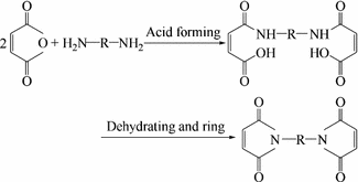 (3.9)
(3.9) -
(2)
Physical properties
BMI monomers are mostly crystalline solids, and aliphatic BMI generally have lower melting points, while aromatic BMI have relatively higher melting points. Asymmetric factors like introduced substituent groups will cause defects in BMI crystals and subsequently affect the melting point. In general, to improve BMI resin processing performance, they require lower melting points to guarantee BMI curing performance. In Table 3.50, some common diphenylmethane BMI monomers are listed together with their melting points.
Table 3.50 Common diphenylmethane BMI monomer melting points Commonly used BMI monomers are generally not soluble in common organic solvents like acetone and alcohol, and only dissolve in strong polar solvents such as dimethyl polyamide (DMP) or N-methyl ketopyrrolidine (NMP).
-
(3)
Chemical properties
Because of the electronic attraction between the two O-hydroxyls in the BMI monomer, its double bonds are electron poor. Therefore, through their double bonds, BMI monomers can undergo additive reactions with active H-containing polymers such as diamines, hydrazides, amides, sulfhydryls, cyanuric acids and hydroxyls. They can also copolymerize with epoxy resins, unsaturated bond contained polymers and other BMI monomers. Self-polymerization in BMI monomers can also take place under catalysis or applied heat. Their curing behavior and post-curing conditions are closely related to their chemical structures.

3.5.1.2 BMI Curing
BMI monomers can self-polymerize and cross-link under proper conditions as shown by the basic reactions given as follows:

Because of their constituent imides and high cross-linking density, cured BMI have superior thermal resistance and their service temperature can reach 177–230 °C with a T g generally higher than 250 °C. Table 3.51 lists some cure BMI resins with their thermal properties. In terms of aliphatic cured BMI, as the number of methyls increases, the initial thermal degradation temperature (T d) of the cured BMI will decrease.
Aromatic BMI have a higher T d than aliphatic BMI, and their T d is closely related to the cross-linking density. Within a certain range, the T d will increase as the cross-linking density increases.
Cured BMI have dense structures and less defects, in addition to much higher strength and modulus. However, their higher cross-linking density results in an increase in molar chain rigidity giving higher brittleness. Therefore, cured BMI have poor impact resistance, lower fracture elongation and toughness.
Cured BMI show complex thermal degradation behavior, and different structures will give different thermal degradation behavior, and this can be summarized as follows:
-
(1)
In cured aliphatic BMI, thermal degradations generally occur at the C–C bonds between the R-chains in the imide rings, but mostly at the C–C bonds closest to the imide rings. The reaction is shown in Scheme 3.11.
 (3.11)
 -
(2)
For cured aromatic BMI, the thermal degradation has a different mechanism compared with that of aliphatic BMI. The degradation will initially produce maleimide rings as shown in Scheme 3.12
 (3.12)
Many factors will affect the cured BMI thermal degradation. To increase the thermal degradation temperature, the monomer quality, cross-linking extent and molecular structures should be taken into account.


3.5.2 BMI Resin Modification
Although BMI has good mechanical properties and thermal resistance, unmodified BMI resins have some drawbacks such as high melting points, dissolution difficulties, high processing temperatures and brittleness of cured resins; among these, poor toughness is the main obstacle to BMI resin application and development. With BMI modification, much attention has been given to the following issues: ① increasing toughness. As a result of continuous development in advanced science and aerospace technologies, stricter demands have been placed on material performance; for example, tougher composites are required in aeronautics, to increase the composite weight-saving efficiency; ② improving processing performance. Although the processing temperatures of BMI resins are far lower than those required for polyimide (PI) resins, they are much higher than those required for epoxy resins. BMI prepregs have poorer viscosity than epoxy prepregs, and this will result in difficulties during composite preparations. Innovative processing techniques such as resin transfer molding (RTM) and resin film infusion (RFI) also require BMI resins to have improved processing performance. Therefore, improving processing performance is an important aspect in BMI modification [5, 70]; ③ decreasing costs. Price is a common concern for all products. Apart from increasing the production volume to reduce raw material prices, high-efficiency and low-cost processing technologies are also becoming more interesting [68].
A number of modifications are available for BMI resins, and the most interesting is to improve resin toughness. Toughening modification for BMI resins includes the following approaches [5, 68]: ① copolymerization with allyl compounds; ② aromatic biamine chain extension; ③ epoxy modification; ④ thermoplastic resin toughening; ⑤ aromatic cyanic ester modification; and ⑥ new monomer synthesis. In addition, studies on BMI processing improvements have been carried out, and in the following sections, some main modifications of BMI resins will be briefly presented.
3.5.2.1 Copolymerization with Alkenyl Compounds
Several types of alkenyl compounds are available for BMI resin modification; the most commonly used compounds in BMI resin toughening and modification are allyl compounds. The prepolymers obtained by the copolymerization of BMI monomers and allyl compounds are stable, dissolve easily, adhere well, are hard and tough cured products, are resistant to wet/hot conditions as well as have superior electric properties, and they are suitable for coatings, molding compounds, adhesives and matrixes of advanced composites.
Allyl compounds are generally very stable at room temperature, and they self-polymerize with difficulty, even at high temperatures or upon the addition of initiators. This is because the free radicals and allyl monomers give additive and transfer reactions, as shown in Schemes 3.13 and 3.14.


In the additive reactions, the generated free radicals are more active and can further react with allyl monomers resulting in the above-mentioned reactions. In transfer reactions, the free radicals are very stable because of conjugation, and no additive or transfer reactions will occur. Most often these reactions are terminated by initial free radicals or self-double radicals, resulting in retarded or inhibited reactions.
The curing reaction mechanism of BMI monomers and allyl compounds is generally more complicated. The double bonds (C==C) in the maleimide rings initially undergo additive reactions with the allyl compounds to form intermediate phases at a ratio of 1:1. At higher temperatures, the double bonds in the maleimide rings and the intermediate phases will undergo Diels-Alder reactions and negative ion imide oligo-polymerization to generate highly cross-linked toughened resins as shown in Scheme 3.15.

-
(1)
Allyl-bisphenol A-modified BMI
Many types of allyl compounds exist. The most commonly used allyl compounds for BMI modifications are O,O′-diallyl-bisphenol A (DABPA) (see 3.16). Diallyl-bisphenol S (DABPS) allyl-aralkyl phenol resins, allyl-ester-ketone resins and allyl epoxy resins are made using N-allyl aryl-amine and other allyl compounds [67].
 (3.16)
DABPA is an amber liquid at ambient temperature with a viscosity of 12–20 Pa·s. The most typical DABPA-modified BMI resin is the XU292 system.
The XU292 system was developed by the Ciba-Geigy Company in 1982, and it mainly consists of biphenyl methyl bismaleimide (MBMI) and the DABPA oligopolymer. With a proper ratio during preparation the prepolymers can dissolve in acetone and can be maintained for more than one week at ambient temperature without demixing. These prepolymers have a low softening point within 20–30 °C, and the prepared prepregs have a good adhering ability. Tables 3.52, 3.53, 3.54 and 3.55 list the XU292 system viscosity, basic properties of the cured resins, the hot/wet resistance and the XU292/graphite composite performance. For the MBMI/DABPA system, the gel-cure curve (Fig. 3.29) shows two reaction transition peaks and they indicate an additive reaction (low-temperature peak) and a ring-forming reaction (high-temperature peak).
Table 3.52 The viscosity of the XU292 system Table 3.53 Properties of the cured XU292 system Table 3.54 Wet/hot properties of the XU292 system Table 3.55 XU292/graphite composite performance Fig. 3.29 
MBMI/DABPA resin gel-cure curve
System I, system II and system III represent mol ratios of 1:1, 1:0.87 and 1:1.12, respectively.
The MBMI/DABPA system prepared using domestic raw materials (mol ratio = 1:0.87) gives the properties given in Table 3.56. This system has good mechanical properties and thermal resistance, but its overall performance is slightly worse than the XU292 system because of poorer raw material quality.
Table 3.56 Properties of the MBMI/DABPA-copolymerized resin system Recently, the Ciba-Geigy Company developed another type of BMI monomer referred to as RD85 (see Scheme 3.17). After copolymerizing with DABPA, the generated prepolymers have low viscosity and are suitable for prepreg production. Apart from their superior mechanical properties and thermal resistance, this resin system also shows good processing performance.
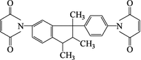 (3.17)
Although DABPA modification can significantly increase the BMI resin toughness, these resins can still not be considered to have high toughness levels. For example, their CAI values evaluated using T300/MBMI-DABPA composites are only in the range of 140–170 MPa, and this resin needs a much higher post-treatment temperature. Despite these shortcomings, further studies have indicated that the MBMI/DABPA system can still become a fundamental resin system for further toughening modification.
-
(2)
Allyl phenol-oxidant resin (AE)-modified BMI [ 68 ]
To improve the BMI resin impregnation property and its adhering ability to fibers, allyl phenol-oxidant resin (AE) with a higher number of –OH groups can be used for BMI modification. AE can be synthesized by the following approach:
 (3.18)
Using different epoxy and allyl compounds with different chemical structures, allyl phenol-oxidant resins with different structures and properties can be generated. The author has himself used allyl-bisphenol A, bisphenol A and epoxy E51 to synthesize AE BMI resins under catalysis conditions and further modified BMI/PEK-C (thermoplastic-modified polyetherketone-PEK) resins. Tables 3.57 and 3.58 list the main properties of this resin system and its composites.
Table 3.57 Properties of the BMI/PEK-C resin modified by AE Table 3.58 Properties of the AE-modified BMI/PEK-C/T300 composite For the BMI/PEK-C resins, before and after AE modification, the T g are 245 and 246 °C, respectively, and the initial thermal degradation temperatures T d are 376 and 374 °C, respectively, indicating that AE modification has little effect on the thermal resistance of the BMI/PEK-C resin.
Table 3.58 shows that pure PEK-C-modified T300/BMI composites have a SBS strength of 93 MPa, while the damaged delaminated areas before and after AE modified are 700 and 550 mm2, respectively. The above results indicate that the added AE can apparently improve the interface bonding between BMI resin matrix and fibers and increase the impact-resistant ability of composites. Therefore, composite CAI values have been significantly increased (from 185 MPa increased to 202 MPa).
-
(3)
Toughening by propenyl ether (PPE) copolymerization with BMI
The reaction between BMI and PPC is different to the reaction between BMI and DABPA. For BMI and PPC, Diels–Alder reactions will take place and then an “alkene” additive reaction will occur to form high density cross-linked “ladder like” copolymers. A typical BMI/PPC system is the Compimide 796/TM-123 resin system. TM-123 is 4,4′-bi (O-propenyl phenyl group) diphenyl ketene, and it is an amorphous solid at room temperature with a low viscosity at 80 °C. It mixes easily and can be prepolymerized with Compimide 796. In the Compimide 796/TM-123 system, the toughness and thermal resistance depend on the ratio of TM-123. At a mass ratio of Compimide 796/TM-123 of 60/40, its toughness will reach a maximum value (G IC = 439 J/m2), and its T g is 249 °C with higher thermal resistance. The main PPC compounds used for BMI modification have the structures shown in Schemes 3.19–3.22.
 (3.19)
 (3.20)
 (3.21)
As for the BMI/DABPA system, BMI/PPC can also become a fundamental resin system for further toughening.
 (3.22)
 -
(4)
Allyl-bisphenol S-modified BMI
For different applications, different allyl compounds with different structures can be used for BMI modification; for example, to increase and improve the BMI thermal stability, allyl-bisphenol S (Scheme 3.23) can be used to copolymerize with diphenyl methane BMI. The prepared resin system has a softening point at 60 °C and a viscosity of 1.2 Pa·s at 110 °C. This resin system has good storage stability. The reaction activity of allyl-bisphenol S and BMI is similar to that of the BMI/DABPA system.
 (3.23)
 -
(5)
Allyl-aralkyl phenol-modified BMI
If allyl groups are introduced into aralkyl resins, allyl-aralkyl phenol can be generated as shown in Scheme 3.17. The allyl-aralkyl phenol resin is a brown solid at room temperature with a softening point within 30–40 °C. It dissolves in organic solvents like alcohol, acetone and methylbenzene. After copolymerization with BMI, the obtained prepolymers have a lower softening point (60 °C) and they can then dissolve in acetone. The cured product of allyl-aralkyl phenol and BMI has superior mechanical performance and thermal resistance. Its HDT is 309 °C, T g 325 °C and T d 490 °C. It has good hot/wet resistance, and after 100 h in boiling water, its HDT and water absorption are 282 °C and 2.3%, respectively. The glass fiber molding compounds prepared by allyl-aralkyl phenol-modified BMI have superior dielectric properties and hot/wet mechanical performance.
 (3.24)
 -
(6)
Other alkenyl-modified BMI compounds
Apart from the above-mentioned allyl compounds, many other types of allyl compounds can be used for BMI modification, for example, N-allyl aromatic amine. Therefore, it is possible to select specific allyl compounds to modify BMI for different purposes.
Two N-allyl aromatic amines are commonly used as shown in Schemes 3.25 and 3.26.
 (3.25)
 (3.26)


3.5.2.2 Binary Amine-Modified BMI
Binary amine modification was an earlier approach to improving BMI brittleness. Generally binary amines can copolymerize with BMI as shown in Scheme 3.27.
BMI and binary amines will initially undergo Michael linear additive block copolymerization; the double bonds in the maleimide rings will then open resulting in a free-radical-type curing reaction. Cross-linked networks will form and the second amine generated in the linear polymers after the Michael additive reaction can also undergo a further additive reaction with other double bonds in the molecular chain-extended polymers.
Kerimide 601 resin was developed by the Rhone-Poulenc Company and is prepared using MBMI and 4,4′-diaminodiphenyl methane at a mol ratio of 2:1. Its melting point ranges from 40 to 110 °C and its curing temperature is 150–250 °C with good processing performance. The prepregs prepared with the Kerimide 601 resin can be stored for 3 months at 25 °C and for 6 months at 0 °C. The performance of the Kerimide 601 resin composites is given in Tables 3.59, 3.60 and 3.61.
Kerimide 601 resins have good thermal resistance, mechanical and electric properties, however, their prepregs have almost no tack, and the toughness of composites is low. In addition, the second amine group (–NH–) generated after the chain extension reaction between the binary amine and BMI can often cause a decrease in the thermal–oxidant stability. Therefore, on the basis of binary amine chain extension modification, an epoxy resin can be added to improve the viscosity of the BMI system. Since epoxy groups can react with –NH– bonds (see Scheme 3.27) to form cross-linked cured networks, the thermal–oxidant stability of the system can be simultaneously improved.


Although the processing performance can be significantly improved by introducing an epoxy resin into the BMI system, epoxy resins can often decrease the thermal resistance of BMI resins. Therefore, the operating temperature of BMI resins modified by an epoxy resin cannot exceed 150 °C. Not much improvement in toughness can be expected either.
3.5.2.3 Thermoplastic Resin-Modified BMI
It is possible to improve resin toughness without losing thermal resistance and mechanical properties using higher thermal resistance thermoplastics (TP) to modify the BMI resin system. The currently used TP resins include polybenzimidazole (PBI), polyethersulfone (PES), polyetherimide (PEI), polyhydantoin (PH), modified polyetherketone (PEK-C) and modified polyethersulfone (PES-C) [68, 69].
Factors that can affect toughening efficiency include primary molecular chain structures, relative molar mass, resin grain size, terminal group structure and content, as well as solvent types and processing techniques. Recent research indicates that the TP toughening of BMI resin has achieved great success and is the principal approach to BMI resin toughening and modification.
In the next section, the main TP used for toughening and modifying BMI resins will be briefly introduced.
-
(1)
Polybenzimidazole (PBI)
The PBI chemical structure is shown in Scheme 3.29.
 (3.29)
PBI is an industrial and commercial thermoplastic aromatic heterocyclic material with superior low-temperature resistance and thermal resistance. Its T g is 480 °C and it starts to degrade at 550 °C in air. PBI easily dissolves into strong polar solvents such as concentrated sulfate acid, dimethylformamide, dimethyl sulfoxide, N-methyl pyrrolidone and 6-methylphosphonic amide. The properties of PBI-toughened BMI resin and its composites are given in Tables 3.62 and 3.63.
Table 3.62 Formula and properties of PBI-modified BMI resins Table 3.63 Mechanical properties of apollo43-600/PBI-modified BMI composites The data in Table 3.62 indicate that adding 10% of three different PBI grain sizes has no effect on the T g and modulus but that G IC increases significantly.
-
(2)
PES, PEI and PH
Other typical TP for toughening BMI resin include PES (Udel P1700), PEI (Ultem) and HP (PH10), which is used for Compimide 796/TM-123 system toughening. The structure and properties of these three TP are given in Table 3.64.
Table 3.64 Structure and properties of some TP resins The properties of the BMI resin and its composites modified by the above-mentioned TP resins are listed in Tables 3.65, 3.66, 3.67. The results in these tables show that the lower T g of TP resins is not good enough for high-performance modified BMI resins. The toughness improves as the TP content increases, but the modulus decreases as the TP content increases, or as the T g decreases. Because the T g of PES is only 190 °C, Ultem and PH TP resins were the first to be selected for BMI modification. These two TP have T g values of 220 °C and higher than 250 °C, respectively. For example, the lower Ultem content resin system of Compimide 796/TM-123/Ultem (ratio = 65/35/13.04) has very high toughness (G IC = 1281 J/m2), strength and modulus. The unidirectional composite made using this resin system and T-800 carbon fiber has very good thermal resistance (the retention rate of interlaminar shear strength is greater than 50%) and toughness (G IC = 585 J/m2). On the other hand, TP modification and toughening will cause a decrease in prepreg tack. Some prepregs will have no tack at all, and this will significantly affect the resin’s processing abilities.
Table 3.65 Properties of the Compimide 796/Tm-123/Tp system Table 3.66 Properties of CF(T800)/Ultem-modified BMI Table 3.67 Properties of CF(T800)/polyhydantoin (PH)-modified BMI -
(3)
Modified polyetherketone (PEK-C)
The structural formula of PEK-C is shown in (3.30). PEK-C has been used to modify the typical two-phase BMI/DABPA system, and the properties of a pure BMI resin are listed in Table 3.68.
Table 3.68 Properties of PEK-C-modified BMI resin  (3.30)
Based on research results, added PEK-C can obviously increase the impact strength of resins. As the PEK-C content is increased, the impact strength of resin casts will initially show an increase and then reach a peak value, after which it decreases. At a PEK-C content of 20%, the impact strength of the resins will have a maximum value of 18.9 kJ/m2, which is a 2.5 times increase compared with the 7.1 kJ/m2 of unmodified BMI without PEK-C. As the PEK-C content is increased, the TP grains in the system will increase and the distance between the grains will become shorter. The distance between the grains and cracks will also become shorter, and the cracks will have more of a chance to encounter TP grains. Therefore, the cracks will terminate more easily. This enhanced ability to terminate cracks is useful in increasing resin toughness. Therefore, as the PEK-C content increases, the toughening will become more significant, and the impact strength will be also increased. The PEK-C that contains hydroxyl groups is more efficient at toughening than end-terminated PEK-C. This may be because the end hydroxyl groups can react with BMI and the two phases of interfacial strength may thus increase.
As shown in Fig. 3.30, a single system phase can be observed by scanning electronic microscopy (SEM). This was obtained from the impact fracture surface of the BMI resin without PEK-C modification. Many clear stripe patterns are present on the surface indicating brittle fracture behavior. Upon the addition of PEK-C, especially a larger amount of PEK-C, the stripe patterns disappeared, which means that tough fracture behavior can be expected. Since the PEK-C grains were dispersed in the BMI matrix, the system displayed two-phase characteristics.
Fig. 3.30 
SEM image of the impact fracture surface of a BMI resin modified by PEK-C
When the PEK-C content reached a certain ratio, a further increase in the amount of PEK-C will result in non-uniform distribution and large dumped grains will be formed. This will result in stress concentration. On the other hand, a too high TP content will result in too many grains, and a too-dense similar grain distribution resulting in fracture cracking exceeding a threshold value. The resin toughness will decrease as the TP content increases.
The T g of the BMI resins modified by PEK-C is listed in Table 3.68, which shows that the T g values decreased 70–80 °C after modification. The reason may be the lower T g of PEK-C (about 230 °C). TGA was used to study the thermal degradation behavior of a modified BMI system, and they found that the degradation initial temperature, termination temperature and maximum degradation rate temperature are 371, 500 and 415 °C, respectively (see Fig. 3.31).
Fig. 3.31 
TG analysis of BMI resins modified by PEK-C
However, PEK-C increased the viscosity of the system resulting in a difficult resin mixing process. Therefore, to obtain a BMI resin system with good mixing, toughness and thermal resistance, an appropriate selection of PEK-C content is very critical. For example, when the ratio of BMI/DABPA/PEK-C is 100/75/15, the resin system can give G IC = 403.8 J/m2 and HDT = 271 °C, while its composites made using CF T300 have G IC = 512 J/m2, which is much higher than that of the T300/XU292 system (G IC = 210 J/m2).
-
(4)
Polysulfone (PS)-modified BMI
The properties of the T300/BMI composites modified by polysulfone are listed in Table 3.69.
Table 3.69 Properties of the T300/BMI composite modified by PS


3.5.2.4 Epoxy Resin-Modified BMI
Epoxy modification is an earlier and more matured approach, and it can improve BMI resin system processing performance and increase the interfacial adhering strength between reinforcements. It can also improve BMI resin system toughness. Epoxy resin reacts with BMI monomers with difficulty, and approaches to modifying BMI system toughness will mainly be the following:
-
(1)
On the basis of binary amine modification, epoxy resins can be added. In this system, the copolymerization between BMI and an epoxy resin can be carried out using a binary amine additive reaction. A cross-linked network will be generated, and chain propagation will take place in BMI and, therefore, the toughness of BMI can be improved. A BMI resin modified by an epoxy/binary amine has good processing ability, for example, prepolymers can dissolve in acetone and prepregs have good adhering and drape abilities.
-
(2)
Use of an epoxy group-containing BMI resin: BMI containing epoxy groups are prepared by the prepolymerization of excess epoxy resins and binary amines. Epoxy groups function as terminal groups, and this BMI can give much improved performance if cured by amine curing agents. For example, 3 mol of BDM, 1 mol of DDM and 7.5 mol phenolic-type epoxy resin (BEN 438) are mixed together in 2-methyl alcohol and left to react for 90 min at 95 °C. After cooling to room temperature, 1 mol of 2,4-biamine-6-phenol-1,3,5 triazine (BG) is added and stirred thoroughly, and then the solution is dried for 24 h under vacuum. BMI prepolymers containing epoxy groups are thus produced. As for other common BMI resins, this kind of BMI gives good thermal resistance after curing under proper conditions. However, the curing temperature required by this BMI is usually lower.
-
(3)
Synthetic modifiers: One such modifier is allyl phenol-oxidant resin which is prepared by epoxy reaction with allyl compounds. It is useful to improve the interface performance between a resin matrix and carbon fiber reinforcements such as the previously mentioned allyl phenol-oxidant resin AE, and this can provide effective modification.
However, the added epoxy resin can often cause a decrease in thermal resistance in the BMI system, and the important point in this modification is the optimization of the constituent ratios and the polymerization procedures to deliver a balance of toughness, thermal resistance and processing ability.
In the 1980s, a very good epoxy-modified BMI system was successfully developed and was designated 5245C resin. To decrease water absorption and increase toughness, bicyanate ester was added to the system. The outstanding feature of this resin system is its superior processing performance, which is similar to epoxy resins, and its good thermal resistance retention rate between 93 and 132 °C with G IC = 158 J/m2.
3.5.2.5 Cyanate Ester (CE)-Modified BMI
Generally, the binary amine can be used for chain propagation modification or the allyl compound can be used for modification. Increase in the toughness by decreasing the resin cross-linking density will often compensate for the loss in material stiffness and thermal resistance. Using epoxy to improve the BMI will result in some thermal resistance loss. For the TP toughening of BMI, although the toughness of the resin system can be significantly increased, the viscosity of the modified resin system can also increase significantly. This will cause the adhering ability of the carbon fiber prepregs to decrease, which means a poorer processing ability for the resin systems. However, the above-mentioned drawbacks can be eliminated by cyanate ester (CE) modification of BMI resin systems.
In the mid-1980s, much attention was given to cyanate ester resins because of their superior combined performance. Cyanate ester resins have an overall performance between that of epoxy and BMI. They can provide the superior processing performance of epoxy resins and the thermal resistance of BMI resins. Their flame-retardant and dielectric properties are also very good, and water absorption is very low. Using CE to modify BMI maintains good thermal resistance and increases toughness in addition to improving the dielectric properties and decreasing the water absorption rate. Generally, two mechanisms can explain the behavior of CE-modified BMI: One is copolymerization between BMI and CE and the other is the formation of an interpenetrated network between BMI and CE resulting in effective toughness. For example, the BT resin from Mitsubishi is regarded to be an interpenetrated system.
CE-modified BMI resin systems have higher toughness, thermal resistance, dielectric properties, wet resistance, anti-abrading, good dimension stability and combined mechanical performances. However, excess halogen cyan is required for the synthesis of cyanate esters. The produced toxic waste liquids are difficult to handle, and this is a main obstacle that limits the wide application of CE-modified BMI systems.
3.5.2.6 New BMI Monomer Synthesis
In previous sections, a number of BMI monomers have been mentioned, but the most commonly used monomer is MBMI, and the second is RD85-101 from Ciby-Geigy. Other types of BMI monomers are not widely used. No specific definition exists with regard to new BMI monomers, but in general the main types will include chain extension, substitution, condensed ring and thiophene BMI monomers. Multi-maleimide BMI monomers such as linear phenolic multi-maleimide monomers also exist.
-
(1)
Chain-extended BMI
In chain extension modification, based on molecular design, by extending the R chain length the chain flexibility and self-spiraling can be increased. Additionally, the cross-linking density of cured resins can be decreased and resin toughness can be improved. Based on the different functional groups and chemical elements contained in the extended chains, chain-extended BMI can be further divided into different types including amide, allanturic, epoxy backbone, ether linkage, sulfate ether bond, imide, and aromatic ester bond BMI as well as silicon contained BMI. In the following sections, the synthesis and performance of some BMI will be discussed.
-
(1)
Amide BMI: A number of methods are available for amide BMI synthesis, but only three are commonly used and these are given below (see Scheme 3.31).
Type I and II can react with maleic dianhydride, dehydrate and cyclize to generate amide linkage BMI.
In amide BMI, the curing temperature will usually increase as the distance between the chains increases, and the initial thermal degradation temperature will decrease. This type of BMI has a series of advantages including flame retardation, thermal resistance, excellent mechanical properties, anti-abrading and electric isolation (see Table 3.70).
Table 3.70 Structure and properties of BMI resins containing amide linkages ①

②

③

 (3.31)
 -
(2)
Allanturic BMI: BMI containing allanturic linkages can be synthesized by the following reactions:
①

②

In ① and ②, amine and maleic anhydride react, dehydrate and cyclize to form allanturic linkage containing BMI.
③
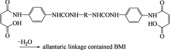 (3.32)
Allanturic BMI requires a higher curing temperature, generally in the range of 203–297 °C, and its initial degradation temperature is equivalent to that of amide BMI. Its maximum degradation temperature and residual carbon rate at 800 °C are lower than those of amide BMI, but its thermal stability is the same as that of common aromatic BMI resins (see Table 3.71).
Table 3.71 Structure and properties of BMI resins containing allanturic bonds -
(3)
Ether linkage BMI: The introduction of ether linkages can increase chain flexibility resulting in an increase in the mechanical properties and flexibility of the BMI resin as well as a decrease in its melting point. Additionally, the reaction activity will decrease, the gel time will be extended and the curing temperature will increase. The introduced ether bonds decrease the T g of the resin system. Table 3.72 shows the structures and performance of some ether linkage BMI.
Table 3.72 Structure and properties of BMI resins containing ether linkages -
(4)
Imide BMI: Flexible chain segments introduced into BMI are useful to increase its toughness, but they also cause a decrease in the thermal resistance and stability of the resin system. Using imide linkages can eliminate this problem as the BMI toughness can be increased and the thermal resistance can be maintained without any loss after the introduction of imide bonds. Imide BMI can be produced by the following synthetic reactions:
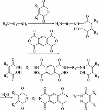 (3.33)
where


This BMI is similar to common BMI in terms of reaction activity, and the curing temperature is in the range of 209–318 °C. The cured resin is stable at 370 °C. The residual carbon rate under nitrogen and at 800 °C is 53–63%. Imide BMI are far superior to BMI that contain amides, allanturic and ether linkages in terms of thermal stability.
-
5)
Urethane BMI: This type of BMI can be synthesized by the following reactions:
 (3.34)
 (3.35)
The introduced urethane bonds will increase BMI reaction activity resulting in a lower curing temperature in the range of 187–248 °C. The cured resins have better toughness, but their thermal resistance is lower than that of commonly modified BMI, and its initial degradation temperature is relatively lower.
-
(6)
Aromatic ester BMI: The BMI containing stiffened rod-pattern aromatic ester groups can be used as thermosetting thermotropic liquid crystal (TLC) polymers and can be prepared by the following synthetic reactions:
Cured BMI containing aromatic ester bonds have superior thermal stability and an initial degradation temperature higher than 500 °C, but they dissolve with difficulty in organic solvents. Their melting points are high, and the range between the melting degradation and the melting temperature is small.
-
(7)
Silicon-containing BMI: In the BMI backbone chain, the introduction of organic silicon structural units can generate cured polymeric products with good processing performance, high flexibility and thermal stability. This is because of the higher Si–O linkage energy and the larger bond spiral degree of freedom. Silicon-containing BMI are usually produced by the condensed polymerization of silicon-containing bisfuran monomers and BMI monomers.
-
(1)
-
(2)
Substituted BMI
In this type of BMI, the hydrogen atoms in the bismaleimide group groups are substituted by other groups to form BMI monomers. For their synthesis, the related diacid will be synthesized first and then further reacted with binary amine to obtain the BMI. Aliphatic and aromatic group substitution will consist of two basic reactions. The structures and properties of the substituting groups significantly affect BMI reaction activity, thermal resistance and dissolution behavior. Some functional groups, after introduction, can impart special functions onto BMI, for example, bromium-substituted BMI will have a very good flame-retardant ability.
-
(3)
Condensed ring BMI
To obtain superior thermal resistance BMI, a condensed ring binary amine and maleic dianhydride can be used to synthesize condensed ring BMI by traditional processing methods. Their structural formulae are given as follows:
 (3.36)
 (3.37)
 (3.38)
where

Condensed ring BMI have superior thermal stability, and their maximum degradation temperature ranges from 450 to 520 °C with a higher residual carbon rate at 800 °C. Its glass cloth-reinforced composites have excellent mechanical performance and flame-retardant properties.
-
(4)
Thiophene BMI
Thiophene BMI has high thermal–oxidation stability and thermal stability. Its synthetic reaction formula is given below: Thiophene BMI usually requires high temperature for curing, and oxygen has little effect on its thermal degradation temperature. Its residual carbon rate at 800 °C is 64–66%.
-
(5)
Special element containing BMI
For special applications of BMI, hydroxyl amine and elemental organic compounds (such as boronic acid, silicon acid ester and titanic acid butyl) are reacted to form special element containing BMI such as those containing boron, silicon, molybdenum and titanium (BBMI, SiBMI, MBMI and TiBMI).


3.5.2.7 Processing Modification
-
(1)
Decreasing the curing and post-treatment temperature
Many modified BMI resin systems are currently available with high-temperature resistance, high strength and toughness. They have good dissolution and viscosity properties. However, these resin systems usually need high-temperature treatment (220–250 °C). High-temperature post-treatment requires processing equipment and molds with higher thermal resistance resulting in an increase in production cost and a decrease in production efficiency. In addition, high-temperature curing may cause an increase in product internal stresses or cracking. The combined curing performance will significantly decrease. To decrease the curing and post-treatment temperature, the following methods can be considered:
-
(1)
Increasing BMI monomer reaction activity: Principally, select and use nucleophilic monomers with higher activity to copolymerize with BMI monomers. Since the double bond on the imide rings in the BMI molecules is affected by adjacent carbonyl groups and becomes electrophilic, the nucleophilic monomers selected to copolymerize with them will result in a larger copolymerization rate. Therefore, the required curing temperature can be decreased. At the North West University in China, Professor Lan Liwen, etc. used styrene and divinyl benzene, with high activity constituents, to copolymerize with the BMI system, and the generated resins have good reactivity between 80 and 120 °C. The gel time is only 9 min at 120 °C, but the shelf life is short at ambient temperature, being only 48 h at 30 °C. Post-treatment at 220 °C is required to obtain products with high performance and cross-linking densities. This means that high activity constituents can reduce the BMI resin gel time at medium or low temperatures, but they cannot absolutely decrease its post-treatment temperature. This problem can often occur when studying increasing reactivity or decreasing post-treatment temperatures and attention should be paid to:
-
(2)
Adding a catalyst or promoter: Adding a catalyst or promoter is another approach to decreasing the processing temperature. For different modified BMI resin systems, suitable catalysts or promoters are different. In Japan, researchers used 2-vinil-4-methyl imidazole (2E4MZ), triethylamine, triphenylphosphonate and peroxidate diisopropylphenol (DCP) to study the catalysis mechanism of N-maleimide phenol/allyl phenol ether, indicating that the former three catalysts are suitable for this resin system. DCP is an effective catalyst. Prof. Lan Liwen et al. studied an imidazole catalyzed MBMI/DABPA systemic reaction and found that imidazole can dramatically accelerate the system gel reaction, but the cured resins have very low thermal resistance after post-treatment for 10 h at 200 °C. The thermal deflection temperature was only 156 °C. A further tracing study found that imidazole can only catalyze BMI self-polymerization and does not catalyze BMI/DABPA system copolymerization, resulting in an unmatched BMI/DABPA ratio. Therefore, DABPA was used in excess. Since DABPA self-polymerizes with difficulty, excess DABPA will result in free states and this causes a dramatic decrease in the thermal resistance and mechanical properties of the resin system. Therefore, proper catalysts or promoters should be able to catalyze or promote the copolymerization of a whole modified system rather than individual constituents in the system.
-
(1)
-
(2)
Special BMI for resin transfer molding (RTM)
RTM is a liquid composite molding (LCM) technique and a low-cost processing technique for high-performance composites [70]. RTM requires resin systems to have low viscosity, long-term suitability and short curing cycles. Currently, the BMI resins used in RTM are prepared by adding allyl or vinyl groups to the system, and then prepolymerization may or may not be used to obtain the required viscosity suitable for RTM. The main commercially available resins include: Compimide 65 FWR from the Shell Co., RTM-BMI used for wheel bosses from the BP Co. The DESBIMID resin is used for cabin cover back beams in FORKKR50 airplane engines and supplied by the DSM Co. In this resin, BMI is dissolved in methacrylate and styrene and injected with a promoter at room temperature. Post-treatment is at 60, 130, 200 and 260 °C for high performance. The typical properties of these resins are given in Table 3.73.
Table 3.73 Properties of some BMI resins
3.5.3 BMI Application
3.5.3.1 Main Commercial BMI Resins
Some commercial BMI resins with their designation and compositions are given in Table 3.74 .
3.5.3.2 BMI Composites and Their Performance
In Tables 3.75, 3.76, 3.77, 3.78, 3.79, 3.80 and 3.81, some high-performance BMI resin composites with their mechanical properties and toughness are presented.
3.5.3.3 BMI Resins and Their Composite Application
BMI resins are widely applied in the following high technology fields:
-
(1)
Isolation materials
They are mainly used as high-temperature impregnation paints, laminates, copper cladding plates and press molding plastics. For example, BMI can be blended with an epoxy resin and active diluting agents to produce H-grade solvent-free impregnated paintings with superior aging, thermal, adhering and chemical corrosion resistance.
-
(2)
Aerospace structural materials
BMI is mainly combined with carbon fibers to make continuous fiber-reinforced composites, which are mainly used for load-bearing structures in military or commercial airplanes and space vehicles, such as wing skins, tails, vertical tails, fuselages and frames.
-
(3)
Anti-abrading materials
They are used for diamond sand wheels, heavy duty sand wheels, brake pads and high-temperature-bearing adhesives.
-
(4)
Functional composites
BMI has a far higher thermal resistance than epoxy resins, and its processing ability is similar. Their hot/wet resistance is excellent, and BMI resin matrix composites are widely used in the aerospace field, for example, the wings, fuselages, tails, various ribs, beams and horizontal stabilizers in F-22 fighter jets are made from high-toughness BMI composites. Table 3.82 lists some high-performance BMI resin composites that are used in airplane applications.
Table 3.82 BMI resins in airplane applications
3.6 Cyanate Ester Resin Matrixes
In the second half of the nineteenth century, the production of cyanate ester (CE) was attempted using hypochlorite ester with cyanides or phenate compounds with cyanogen halides, but these attempts were not successful [71]. The obtained products were only the isocyanate ester or other compounds. In the late 1950s and early 1960s, R. Stroh and H. Gerber reported the first successful synthesis of a real cyanate ester. In 1963, a Germany chemist E. Grigat developed a simple method in which phenol compounds and cyanogen halides were used to synthesize cyanate esters. Since then, E. Grigat and his company have carried much research into this subject. However, since the cyanate ester synthesis as well as the polymerization mechanism was not fully understood in the early stages, the processing and operating capabilities of cyanate ester resins were influenced, and the promotion and application of cyanate ester resins was severely limited. In 1976, the Miles Co. introduced a resin to the market that could be applied in the electronics industry. This was a butanone solution containing 70% cyanate ester. However, this resin was inconsistent during vapor welding immersion testing, and it was withdrawn from the market by Miles in 1978. Research continued and with the advancement of science and technology in the 1980s products with future applications were successfully developed.
Cyanate ester resin is usually defined as a phenol derivative containing two or more cyanate ester functional groups. They can undergo tri-ring reactions under applied heat and catalysis and form highly cross-linked networks and structural macromolecules containing triazine rings. Cured cyanate ester resins can provide low dielectric constants (2.8–3.2) and a very small dielectric loss tangent (0.002–0.008), a high glass transition temperature (T g = 240–290 °C), low shrinkage and water absorption (<1.5%), good mechanical performance and adhering ability. Cyanate ester resins have a similar processing ability to epoxy resins, and no small molecular volatiles are released during the curing processes. Cyanate ester resins are mainly used in the following industries: as printed circuit boards in high speed and frequency digital applications, high-performance wave penetration materials and aerospace high-performance structural composite matrices.
3.6.1 Synthesis of Cyanate Ester Resin Monomers
Extensive research has been reported regarding cyanate ester resin synthesis, and many approaches are currently available. Only one method has been commercialized [72,73,74] for the preparation of high-temperature-resistant cyanate ester resin. This method consists of alkali catalysis using cyanogen halides and phenol compounds to prepare cyanate ester monomers:
In Eq. 3.39, Hal can be Cl, Br and I but bromine cyanide is most popular because it is a stable solid at ambient temperature. Its reaction activity is adequate and it has low toxicity. ArOH can be a single phenol, a multi-phenol or aliphatic hydroxyl compounds. The alkali in the reaction medium is usually an organic alkali like triethylamine that can accept protonic acid. This type of reaction is usually carried out in organic solution at −30 to 20 °C. The reaction temperature may differ slightly depending on the phenol used, for example, the reaction temperature required for the reaction between bisphenol A and bromine cyanide is usually controlled at approximately −30 °C [75]. The initial products generated in the reaction will be subject to vacuum distillation or recrystallization to yield purified products. The 4,4′-dicyanate ester-diphenyl methane is a low-viscosity liquid, and all the other commercialized cyanate ester monomers are crystallized solids. For the synthesis of cyanate ester monomers, two main side reactions take place: One is the tri-polymerization of some of the cyanate ester monomers under alkali catalysis to form cyanate ester monomer oligopolymers in non-crystallized half-solid states [Eq. (3.40)], which occurs because the synthesis is carried out under alkali ambient conditions. Under alkali conditions, the small amount of water in the system or in the phenol may continuously react with the generated cyanate ester to form amine formic ether or an imino-carbonic ester [Eqs. (3.41) and (3.42)]. The small amount of impurities will affect the storage stability of the synthesized products and the service performance of the end products (such as their thermal resistance and hydrolysis resistance) [76].
It is necessary to point out that aliphatic cyanate esters can easily undergo isomeric reactions to form isocyanate esters:


This synthesis method for cyanate esters is highly suitable for industrial production with its simple production procedures, high output rate and product purity. Additionally, the cyanate ester produced can provide very good stability, and their end products can give superior service performance.
The second synthesis method for cyanate esters is also the earliest method used for cyanate ester synthesis. It comprises the reaction between alkaline phenate (phenol sodium) compounds and cyanogen halides. In these syntheses, the generated cyanate ester can undergo tri-polymerization easily, or react with phenol to form imino-carbonic esters under strong alkali catalysis [77]:

When these syntheses were developed, the production rate was very low, and the purity of the products was not high either. Therefore, the scaling of this synthetic method to commercial production was not feasible. However, according to some literature reports, high-purity aromatic cyanate esters can be prepared by this method if proper processing conditions are selected. For example, amine catalysis at low temperature using polyalkylphenol amine salt to react with the abundant cyanogen halides in organic solution can also give high-purity cyanate esters.
A year after the preparation of the cyanate ester shown in Eq. 3.39 by E. Grigat, D. Martin and Berlin also developed a new method for cyanate ester preparation. They used the thermal decomposition of phenoxyl 1,2,3,4-thiatriazole and oxethyl 1,2,3,4-thiatriazole to prepare cyanate esters [78]:


In Eqs. 3.45 and 3.46, the R group can be aromatic groups or aliphatic groups, and thus aromatic cyanate esters as well as aliphatic cyanate esters can be produced at a high production rate and product purity. However, cyanate ester production using this method is often lower than that given in Eq. 3.39. The cyanate ester yielded by the method given in Eq. 3.45 is only 60%, while that from Eq. 3.46 is 70–80%. Additionally, the synthetic process for this type of synthesis is very complex.
Cyanate ester synthesis can also be conducted by adding bromine to potassium cyanide or sodium cyanide aqueous solutions. In the presence of tert-amine, the solution is dispersed in a phenol carbon tetrachloride solution and the reaction will occur as follows (3.47) [72]:
The advantages of this method are the elimination of the very toxic cyanogen halides, which vaporize easily or undergo sublimation during preparation. This process is a one-step simple reaction, but the purification of the final cyanate ester products is difficult.
Jesen and Holm tried to use thiocarbamic acid ester with heavy metal oxidants to eliminate sulfide hydrogen for the preparation of cyanate ester, but the yield is only 40%, and it is not a successful synthetic approach [72].

In Table 3.83, some applicable cyanate ester resins are given with their structures and thermal performance. Bisphenol F cyanate ester is a low-viscosity liquid, and the other monomers are crystallized solids. These crystals have lower melting points than those of the phenol compounds used for these preparations, and thus, the cyanate ester has a good processing ability.
3.6.2 Curing Reaction of Cyanater Ester Resins
3.6.2.1 Curing Reaction Mechanism
Research has shown that highly purified aromatic cyanate esters cannot polymerize even under applied heat conditions. However, for functional groups containing partial negative charges like oxygen and nitrogen, the adjacent carbon atoms show strongly electrophilic behavior.

Therefore, with a nucleophilic reactant the reactions of cyanate ester functional groups can be catalyzed either by acid or by alkali.
Model cyanate ester compounds with a single functional degree react in aqueous solutions containing active hydrogens (or acids) with difficulty. It has been reported that at 100 °C for 5 h in butanone and acetone solutions and without any catalysis, a reaction mixture containing the model compounds and tert-butyl phenyl cyanate ester (PTBPCN) was evaporated to remove the solvent followed by N-NMR analysis. The results showed that no reactions took place. The same system showed apparent tri-polymerization after the addition of 200 × 10−6 zinc octoate catalyst and heating for 1 h. Additionally, a hydration reaction gave a small amount of cyanate ester (Eq. 3.41), as shown in Fig. 3.32 [79].

N-NMR spectrum of the nitrogen-rich PTBPCN reaction
-
(1)
No catalysis (100 °C × 5 h); (2) 200 × 10 −6 zinc octoate catalysis (100 °C × 1 h)
Some of the cyanate esters prepared by different synthetic methods will not contain residual phenols, while others will contain a little. The curing reaction is very slow, even for the residual phenol-containing cyanate esters. To polymerize high-purity cyanate ester monomers, two kinds of catalysts should be added to the system: One is an active hydrogen-containing compound such as a single phenol in water (2–6%) and the second is a metal catalyst such as a Lewis acid or organic metal salts. Since cyanate ester functional groups contain lone-pair electrons and they donate electron π bonds, they easily form complexes with metal compounds. Therefore, metal compounds like metal carboxyl acid salts, ZnCl2 and AlCl3 can be used as catalysts to catalyze cyanate ester functional group tri-polymerization. However, these metal salts have very poor solubility in cyanate ester resins resulting in very low catalysis efficiency. To increase the catalysis efficiency, organic metal compounds that can dissolve in cyanate ester resins should be used. In Fig. 3.33, the polymerization mechanisms of cyanate ester reactions under metal salt or phenol catalysis are given [80,81,82]. In these reaction processes when using cyanate esters with good flow ability, the metal ions will first concentrate the cyanate ester molecules and surround the ester upon which the phenol hydroxyl will undergo a nucleophilic addition reaction with the cyanate ester in the surrounding metal ions to form an imide carbonized ester, and undergo a continuous addition reaction with the two cyanate esters.
Fig. 3.33 
The reaction mechanism of cyanate ester polymerization under catalysis
Finally, the ring will close and remove the molecular phenol to form a triazine ring. In this reaction process, the metal salt is the principal catalyzing agent, and phenol is the coordinating catalyzing agent, which promotes the ring-closing reaction by proton migration.

3.6.2.2 Curing Reaction Kinetics of the Cyanate Ester
In the tri-ring reaction, the polymerization consists of four fundamental reactions related to the cyanate ester monomers, metal catalyzing agents and the cyanate ester/catalyzing agents. The cyanate ester functional groups will react first with the metal catalyzing agent ions to form a complex. A chain expansion by the complex will take place and promote a ring-closing reaction by proton migration because of the active hydrogen-containing compounds. The four basic reactions are as follows:
where Cy is the unreacted unit; T is the triazine ring; M is the metal ions; C1M*, C2M* and C3M* are the metal ion/cyanate ester complexes with ratios of 1:1, 1:2 and 1:3, respectively; K i is the reaction speed constant of the basic reaction. The general reaction can be expressed as:
In the reaction process, assuming that the complexes have the same concentrations at all reaction stages, that is, [C1M*] = [C2M*] = [C3M*], and considering the above-mentioned reaction equations, it can be concluded that K 2 = K 3 ≥ K 1([M] ≥ [CM]). The consumption rate of the cyanate ester functional groups is thus:
Additionally, assuming that the metal ion concentration is nearly equal to the initial concentration of the metal catalyst, which is [M] = [M0], Eq. (3.49) can be expressed as:
From Eq. (3.50), the reaction kinetics of the cyanate ester tri-polymerization obeys a secondary reaction kinetic model. From the deduction of the kinetic equation, the reaction speed constant of the tri-polymerization will be proportional to the ion concentration of the metal catalysts. Based on the Arrhenius equation and the different reaction speeds of the different catalysts at different temperatures, the reaction activation energies of the polymerization with different metal catalysts can be calculated. In Table 3.84, the reaction speed constants, activation energies and frequency factors of several BPACy formulae are given. In terms of the reaction speed constants, the catalysis abilities of the metal catalyzing agents will be Zn > Mn > Co, and the reactivity of the metal catalysis is related to the coordination number of the metal ions. The Zn salts have the lowest coordination number, and their complexes will give a higher diffusing ability in the cyanate ester ring-forming processes. Therefore, its catalyzed BPACy resins will have higher reactivity. Based on these experimental results, the resins prepared using various catalysts have reactive activation energies of 75–104 kJ/mol. It is necessary to point out that the kinetic equation given in Eq. 3.50 is only applicable to the sections controlled by reaction kinetics while the kinetics controlled sections are found where the curing temperature is about 30 °C higher than the glass transition temperature.
For cyanate ester curing, IR spectra can be used to monitor the reaction and the band at 2270 cm−1 disappears while new absorption bands appear at 1565 and 1370 cm−1. The band at 2270 cm−1 is a C≡N tension vibration, while those at 1565 and 1370 cm−1 are vibration absorptions of the triazine rings from the cyanate ester tri-ring reactions. Figure 3.34 shows that under catalysis by a 100 × 10−6 mol/L Zn salt and a 4% single phenol solution, concentration fraction changes in the cyanate ester functional degree in the BPACy resins at different temperatures are obtained. This shows the cyanate ester reaction extent, as monitored by IR. From Fig. 3.35, when the transformation of the cyanate ester function is higher, that is, when the resin is gelled, the flow ability of the reaction system decreases and the reaction does not fit the kinetics model any more. The reaction will thus be controlled by mass transfer. After the reaction system becomes gelled, the active hydrogen-containing compounds, especially nonyl phenol, will be more efficient at catalyzing the cyanate ester functional group transformation compared with metal ions, and this may be because the nonyl phenols undergo mass transfer better in this system.

Correlation between speed constant and metal catalyst concentration. ●, ■ are the Co and Mn catalysts (containing 4% phenol hydroxyl)

Comparison between model and experimental results—model of calculated results. ●, ■, □, ▲ are the experimental results obtained at 130, 150, 175 and 200 °C, respectively
3.6.2.3 Effect of Catalyst on the Curing Reaction
In cyanate ester curing processes, the type of metal ion and the concentration of catalysts can have a significant effect on the curing reactions. Additionally, the organic ions of the catalysts and the concentrations and types of activated hydrogen compounds in the coordinated catalysts will greatly affect the curing reactions.
Figure 3.36 shows the effect of nonyl phenol concentration on the thermal deformation temperature of the BPACy cast resins cured under copper naphthenate catalysis [81]. At a nonyl phenyl concentration less than 2% (0.013 OH/OCN mol ratio), the system is not fully cured at 170 °C for 3 h as determined by FTIR and DSC analysis. The curing degree is only in 70–75%. At a phenol concentration of 6%, the curing degree is 91%, and the HDT is 186 °C. This is because the reaction speed is controlled by nonyl mass transfer after the resin has gelled. Therefore, a higher concentration of nonyl phenol will be more effective during the curing reaction of the gelled cyanate ester. Curing at 250 °C for 1 h gives a cyanate ester cast resin containing 2% nonyl phenol that gives a HDT of up to 260 °C (transfer rate = 97%).

Effect of nonyl phenol concentration on the heat deformation temperature (HDT) of the BPACy cast resins cured under copper naphthenate catalysis
For the 6% nonyl phenol cast resin, the HDT was only 220 °C (transfer rate > 98%). The reason is that a proper amount of nonyl phenol can cause –OCN to be sufficiently tricyclized into triazine rings, and this will prevent phenol reacting with –OCN to form an imide carbonized ester (cause resin cross-linking density to decrease), resulting in very high HDT. A high concentration of phenol (6%) can cause –OCN to be fully transferred, but the phenol can react with –OCN and cause a decrease in the resin’s cross-linking density, resulting in a lower HDT. In Fig. 3.37 [83], the BPACy resins cured under various post-curing conditions and their T g changes with different nonyl phenol concentrations are shown. These results indicate that the 250 °C post-cured samples will show a decrease in T g as the nonyl phenol concentration increases. If the post-curing temperature is increased to 285 °C, the resin T g (2% nonyl phenol) does not increase by comparison with 250 °C post-curing. However, for resins without nonyl phenol, their T g increases from 270 to 295 °C. Therefore, at a nonyl phenol content less than 2%, high-temperature post-treatment is necessary for a high transfer rate. The nonyl phenol concentration will also significantly influence the cured resin’s mechanical, thermal resistance and chemical resistance performance. Table 3.85 lists some BPACy resins and their mechanical and thermal resistance performance [81].

Correlation between BPACy resin T g and nonyl phenol concentration. Maximum curing temperature: □ −175 °C; ▲ −285 °C; ● −300 °C
The active hydrogen compounds can also dramatically affect the curing reaction as well as the cured resin’s performance. Table 3.86 lists the effects of several different phenols on the cyanate ester cure reaction and the cured resin’s performance. The type of phenol can influence both the reaction speed and the mechanical properties. The formula containing o-phenyl bisphenol gave higher thermal resistance, but its mechanical properties are far poorer than those of the other formulae, and its toughness is also lower [84].
Figure 3.38 shows gel time curves for the BPACy reaction catalyzed by different acetylacetone cobalt concentrations [85]. From this figure, cobalt salts of the same concentration and with different negative ions gave different corresponding gel times. Carboxylic salts provide a far better catalyzing efficiency than acetylpropyl salts. In fact, acetylpropyl salts can be considered to be a potential catalyst because the catalyzed and cured resins will have a higher hydrolyzing resistance than that produced using other types of catalysts. Table 3.87 shows the effects of several copper ion complexes on the curing reactions. In Table 3.87, the time needed for resin gel hardening with less than 2% mol/CON catalyst and at 25 °C is listed. These results also show the effect of negative ion types on resin reactivity [86].

Correlation between gel time and cobalt salt types and concentrations. 1—Acetylacetone cobalt; 2—naphthenate cobalt; 3—octoate cobalt
The effect of different metal ions on the cyanate ester curing reaction is important [80, 84]. In Table 3.88, the effects of acetylacetone metal ions on the cyanate ester cure reaction are listed. At 104 °C, the gel time upon catalysis by Mn2+, Mn3+ and Zn2+ was only 20 min, while Co3+ required 240 min. The mechanical performance of the cured resins catalyzed by these metal salts showed large differences as their bending strengths varied from 178 to 119 MPa. Their bending strains varied from 4.8 to 7.7%. Among these catalysts, Zn2+, Cu2+, Mg2+, Co2+ and Co3+ were found to be good catalysts although Fe3+, Ti3+, Mg2+, Pb2+ and Sn2+ also gave high catalysis efficiencies, and their catalysis upon cross cyanate ester hydration should also be considered.
The effects of different metal ion types and concentrations on the thermal stability of cyanate ester cross-linked networks will be also different [83]. Under catalysis by 4% nonyl phenol and metal catalysts at 170 °C for 1 h or 255 °C for 1 h as curing conditions, the glass transition temperature T g was found to be related to the catalyst type and concentration (shown in Fig. 3.39). At a metal catalyst concentration of 100 × 10−6 mol/L, the maximum glass transition temperature reached 250–260 °C. However, using Zn salts as catalysts for these resins resulted in a decrease in the T g as the catalyst concentration increased. At a Zn catalyst concentration of 750 × 10−6 mol/L, the resin’s T g decreased to 190 °C, while using Mn and Co salts as catalysts did not give a change in T g with different catalyst concentrations. Figure 3.40 shows TGA results [87, 88] for BPACy resins after curing with 4% nonyl phenol and catalysis by 100 × 10−6 mol/L Zn, 750 × 10−6 mol/L Zn and 750 × 10−6 mol/L Mn. The sample obtained using 750 × 10−6 mol/L Mn gave 450 °C or higher in terms of initial thermal decomposition temperature, while for 750 × 10−6 M Zn the initial thermal decomposition temperature was 250–300 °C. Even for the 100 × 10−6 mol/L Zn sample, the initial thermal decomposition temperature only reached about 400 °C. In addition, the samples catalyzed using 100 × 10−6 mol/L Zn and 750 × 10−6 mol/L Mn showed a second weight loss stage at 600 °C, while the 750 × 10−6 mol/L Zn-catalyzed samples had second and third stages at 500 and 600 °C. Based on GPC catalysis studies, single functional group model compounds may generate a certain amount of cyanate ester dimers, and the generation of dimers may be a reason for the lower glass transition temperature and the thermal decomposition temperature of the Zn salt catalyzed and cured resins.

T g changes with different catalyst types and concentrations. ■, ○, ▲, □, ● are zinc acid salt, naphthenate zinc, zinc acid manganese, naphthenate manganese and acetylacetone cobalt

TGA analysis of the BPACy resins catalyzed by 4% nonyl phenol and Zn+ or Mn+. a—750 × 10−6 Zn2+; b—100 × 10−6 Zn2+; c—750 × 10−6 Mn2+
3.6.3 Cyanate Ester-Modified Epoxy and BMI Resins
As discussed in section one, cyanate ester resins can provide superior service performance and processing abilities compared with other resins. Therefore, using cyanate esters to modify epoxy, BMI and other thermosetting resins can improve the service performance of these resins (hot/wet resistance and impact resistance) and also their processing abilities.
3.6.3.1 Cyanate Ester-Modified Epoxy Resins
Epoxy resins are a class of thermosetting resins with good combined performances and have gained wide application. However, common epoxy resin matrixes contain a large amount of polar groups like hydroxyls that are generated during the curing reactions resulting in higher water absorption for the resin matrixes. This may cause a significant decrease in the mechanical properties of the composites under hot/wet environments. Using cyanate ester resins to modify (cure) epoxy resins eliminates the possibility of hydroxyl and amine polar groups in the cured resins. Therefore, water absorption is lower, and the resins will have good hot/wet resistance. The cured resins contain five oxazoline heterocyclic and six triazine structures and thus have good thermal resistance. The large amount of –C–O– ether bonds contained in the cured resins can provide good toughness. In general, adding 30% cyanate ester can cure bisphenol A epoxy resin at less than 180 °C, and the composites will have good processing performance.
-
(1)
The curing reaction in cyanate ester-modified epoxy resins
To study the copolymerization mechanism of cyanate ester/epoxy mixtures, a single functional degree cyanate ester model compound, CPCy and epoxy PGE were used to carry out a copolymerization mechanism study.

Under catalysis by titanic acid ester, equal molar quantities of CPCy and PGE were reacted at 177 °C, and it was found that 60% of the cyanate ester functional groups were transformed into tri-polymers. GPC analysis showed that the reacted products of equal molar quantities of CPCy and PGE consist of 57% cyanate ester tri-polymers, 13% oxazoline, 4% cyanate ester compounds and 26% PGE.
Figure 3.41 shows the instant composition distribution of the CPCy and PGE reaction [80, 89, 90]. When HPLC was used to monitor the residual compound distribution of the CPCy/PGE system as well as the distribution of newly generated compounds under different reaction times (Fig. 3.42) [91], it was found that PGE was consumed at a lower rate than CPCy. Additionally, as the reaction proceeded, the tri-polymer content will reach a maximum value over a short reaction time and will then gradually decrease. It will finally reach a lower equilibrium value at the end of the reaction (this equilibrium value is related to the CPCy to PGE ratio). When the tri-polymer content began to decrease, oxazoline was generated.
Fig. 3.41 
GPC peak distribution of equal molar quantities of blended CPCy and PGE reactants
Fig. 3.42 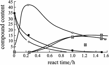
The compound content distribution in the CPCy and PGE system. +—CPCy; ⌧—PGE; ■—tri-polymers; ○—oxazoline
FTIR is an important method for the study of reactions in the cyanate ester/epoxy resin system. The following table lists the infrared absorbing characteristic frequencies that correspond to the chemical functional groups in cyanate ester/epoxy co-curing:
The FTIR spectra of the CPCy/PGE blended system indicate that unreacted CPCy, PGE and generated CPCy tri-polymers, oxazoline and polyether structures are present in the blended reaction compounds.
From FTIR analyses (Fig. 3.43), the consumption rate of cyanate esters is much faster than that of epoxy. During the early reaction stage, tri-polymerized cyanate ester structures are apparent in the FTIR. As the curing reaction proceeded, the characteristic peaks of the tri-polymerized cyanate ester (1565 and 1372 cm−1) were dramatically reduced, and even disappeared, while the characteristic peak intensities of the oxazoline structures (1760 and 1690 cm−1) increased gradually. Therefore, when the ratio of BPACy/bisphenol A is less than 1, oxazoline and polyether will be the main structures present in the cured resins while low amounts of the triazine structures survived.
Fig. 3.43 
FTIR spectra of cyanate ester/epoxy copolymerization. 1—Cured cyanate ester; 2—epoxy/cyanate ester 180 °C for 15 min; 3—epoxy/cyanate ester 180 °C for 1 h; 4—epoxy/cyanate ester 180 °C for 1 h and 200 °C for 2.5 h
In summary, it has been found that the copolymerization of cyanate ester and epoxy resin will basically follow the mechanism as given as follows:
 (3.51)
 (3.52)
 (3.53)
 (3.54)
From the FTIR analyses, a ring-opening reaction to form polyether will essentially occur during the later reaction stages in the epoxy functional groups. When organic metal catalysts were used, the epoxy compound PGE can undergo either positive-ion polymerization or coordination polymerization to form polyether structures:
 (3.55)
 (3.56)
It is well known that cyanate esters and epoxy resins do not undergo curing reactions independently without catalysts and curing agents. However, when blended compounds of cyanate ester and epoxy resin undergo curing reactions, only a small quantity of cyanate ester is required to promote epoxy resin curing. Additionally, a small quantity of epoxy resin can also promote the curing of cyanate ester; in other words, cyanate esters and epoxy resins can intercatalyze each other (Fig. 3.44) [92].
Fig. 3.44 
Cyanate ester/epoxy mixed compounds with various ratios and their viscosities
Using cyanate ester to cure epoxy resin can give fully cured resins without catalysts, but catalysts can also be used for curing reactions. When catalysts are added, the resin will have a different curing mechanism and molecular structure. Table 3.89 shows the effect of various catalyst concentrations on the reaction activity of this resin system. In Table 3.89, formula D gives a very short gel and cure time (1.2 min) and very large reaction activity. This formula almost meets the RTM processing requirement for resins. Figure 3.45 shows curves showing the curing degree changes with curing time (FTIR was used to determine the epoxy curing degree). The resins are both catalyst-free and contain 500 × 10−6 M acetylacetone catalyst, and were cured at 180 °C. For the catalyst-free resin, after 30 min of curing the curing degree of the epoxy functional groups only reached 72% while 97.5% was obtained for the resin containing 500 × 10−6 M acetylacetone as a catalyst. However, the resin containing the catalyst was subject to a 3.5 h reaction to reach a certain curing degree (97%). The different catalysts will cause the cured resins to have a slight difference in structure. Table 3.90 shows FTIR peaks at 1695 and 1760 cm−1 with intensity changes. The resins used in this analysis were catalyzed by different catalysts. These differences in structure will influence the physical and mechanical properties as well as the thermal stabilities of the cured resins.
Table 3.89 Activities of the cyanate ester/epoxy with different catalyst contents Fig. 3.45 
Effect of catalysts on epoxy functional group curing degree
Table 3.90 Structure change in cured resins catalyzed by various catalysts -
(2)
The physical and mechanical performance of cyanate ester-modified epoxy resins
As discussed before, epoxy resins after modification by cyanate esters can offer good hot/wet resistance and impact resistance, and this will depend on the molecular structures of the cured resins. Cyanate ester-modified epoxy cured resins will give a much lower water absorption rate than aromatic amine-cured epoxy resins and can reach an equilibrium state in a short time. Therefore, the decrease in HDT will also be smaller than for other resins. Figure 3.46 shows a comparison between several resins in terms of their water absorbing abilities. Cyanate ester-modified epoxy resins have a much lower water absorption rate than the AG-80/DDS resin system, the hot/wet resistant epoxy 5228 system and the BMI-MDA system. This is because of the high amount of generated hydrophilic hydroxyl groups from the curing processes of the epoxy resins (such as AG-80/DDS, 5228). Additionally, there will be some trialkylamine as well as incompletely reacted polar groups such as primary amine and secondary amine trialkylamine contained in the cross-linked network structures. In the cyanate ester-cured epoxy resin systems, no hydroxyls will be generated during the resin curing processes, and not many polar groups will be present either. The resin castings will thus have a lower water absorption rate, and the main water absorption model is water dissolved in the resin matrixes.
Fig. 3.46 
Comparison between resins with their water absorption. 1—Cyanate ester/epoxy; 2—5228 epoxy; 3—BMI-MDA; 4—AG-80/DDS
Figure 3.47 shows the effect of water boiling time on resin HDT. For cyanate ester homopolymers and the MY720/DDS resin system, HDT is still slightly lower after 500 h in boiling water, while the HDT of the cyanate ester-modified epoxy resin reaches equilibrium after 60 h in boiling water. The HDT difference between dry and wet conditions ranges from 10 to 20 °C.
Fig. 3.47 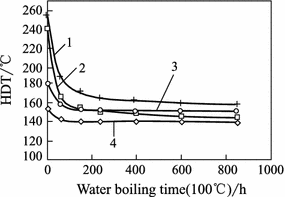
HDT changes for several resins with different boiling water times. 1—BADCy homopolymer; 2—My720/DDS epoxy; 3—BADCy/DGEBA 43%/57%; 4—BADCy/DGEBA 35%/65%
Table 3.91 shows the cyanate ester epoxy resin’s physical and mechanical properties [90]. Different structures will give different epoxy resin mechanical properties. The cyanate ester-cured DGEBA gives higher bending strength and fracture elongation.
Table 3.91 Effect of epoxy resin structure on the performance of CE-modified epoxy cured resins The cyanate ester improves the epoxy resin’s mechanical properties and also its electrical performance. Its electrical performance is superior to that of amine-cured epoxy resins and BMI-MDA resins as given in Table 3.92.
Table 3.92 Dielectric performance of CE-modified epoxy and other resins Using the cyanate ester functional group to react with electron-deficient unsaturated olefinic compounds is an important cyanate ester modification approach [80]. In Japan, Mitsubishi’s commercialized BT resin series is a major class of reactant for cyanate ester and BMI resins. In BT resins, the main constituents are the bisphenol A dicyanate ester and diphenyl methane bismaleimide. Figure 3.48 shows the major reaction equation of cyanate ester and BMI. For cyanate ester-modified BMI, the addition of epoxy, unsaturated polyester, acrylate and thermosetting fire-retardant agents can give various materials that meet different special application needs. BT-cured resins can increase the impact, electric and processing performance of BMI resins, or improve the hydration resistance of cyanate ester resins. In terms of thermal resistance, the cured BT resin series will range between the BMI and cyanate ester resins. Figure 3.49 shows the glass transition temperature of the BMI/CE resins with different ratios. Using a blended compound of CE, BMI and epoxy to carry out co-curing, the generated resins offer much better processing ability and toughness while the service temperature can be further decreased. Figure 3.50 shows the correlation between glass transition temperature and different constituents in a co-cured BMI/CE/epoxy resin system.
Fig. 3.48 
BMI/CE copolymerization mechanism
Fig. 3.49 
BMI/CE resins with various BMI mol ratios and their T g
Fig. 3.50 
Various BMI/CE resins with their T g


Group | CH2 | –C≡N | –C–O– | C=N | Oxazoline ring | Triazine ring | Triazine ring ≡C–O– | Aromatic ether | Epoxy |
|---|---|---|---|---|---|---|---|---|---|
Wave number/cm−1 | 2875 | 2230 | 1760 | 1695 | 1608 | 1565 | 1365 | 1245 | 915 |
3.6.3.2 Cyanate Ester-Modified Bismaleimide Resin (BMI)
The Chemical Department of Surrey University in the UK reported the copolymerization of allyl cyanate ester and bismaleimide as a systematic study [92,93,94]. A 1-cyanoto-2-allyl phenyl and N-phenyl maleimide (N-PNMI) model mixture was subjected to 140 °C for 4 h and 150 °C for 5 h. A C-NMR analysis showed a very strong absorbing carbon atom shift with 174.51 × 10⁻⁶ M triazine, as well as two different carbon atom shifts with 178.85 × 10⁻⁶ M and 175.75 × 10⁻⁶ M for the weaker asymmetric hydroxyls (for the allyl phenyl and N-phenyl maleimide reactants, the same two chemical shifts are shown in the C-NMR spectrum). In this set of C-NMR spectra, very strong carbon atom chemical shifts from unreacted carboxyl groups (Fig. 3.51) were also present. This indicated that the major reaction in this process is a tricyclization reaction of the cyanate ester functional groups. The allyl then further reacted with maleimide, and the reaction mechanism is shown in Fig. 3.52. In dynamic mechanical thermal analysis (DMTA), allyl cyanate ester and BMI blends gave a T g of 350 °C after curing, while diphenyl methane BMI only gave a T g of 210 °C after curing by the same curing process. This shows that this BMI is not completely cured using this process as shown in Fig. 3.53.

C-NMR of the allyl cyanate ester and N-PNMI cured resins. 1—Allyl phenyl and N-PNMI reaction; 2—allyl CE and N-PNMI reaction

Allyl cyanate esters and BMI copolymerization mechanism

DMTA curves for allyl CE/BMI. BMI and CE resins. C—Allyl CE/BMI copolymer; E′—storage modulus; E″—loss modulus; the top 3 are storage modulus curves; the bottom 3 are loss modulus curves
3.6.4 Cyanate Ester Resin and Its Composite Performances and Applications
3.6.4.1 Cyanate Ester Resin Structure and Performance
Extensive triazine and aromatic rings or rigid ester rings (such as in the Xu-71787 resin system) are contained in cured cyanate ester resin molecular networks, and the triazines as well as the aromatic rings are joined by ether linkages, and cured cyanate ester resins can thus give good thermal and chemical resistance and good impact resistance as well as dielectric properties.
Since different cyanate ester monomer structures exist, the physical states and processing behavior of these monomers will be very different. Table 3.93 lists some commercialized cyanate ester monomers and their physical properties [80]. Some of these monomers are crystalline and have different melting points as there are slight variations between the different structures in CE crystals. ArocyL-10 and RTX-366 are supplied as liquids, and ArocyL-10 can be used as a RTM resin. RTX-366 is crystalline with a melting point of 68 °C. It crystallizes from a light yellow liquid during storage. Xu-71787 is a half-solid material containing some oligopolymers. To improve the crystallized cyanate ester monomer’s processing ability, the cyanate ester monomer should be partly homopolymerized into amorphous prepolymers with physical states ranging from tacky half-solids to brittle solids. Table 3.94 lists some cyanate ester resins supplied with prepolymers [80, 95, 96].
-
(1)
Cyanate ester environmental resistance
The environmental resistance of cured cyanate ester resins will depend on the chemical structures of the CE monomer backbones, the catalysts used and the curing conditions. In this section, the effect of chemical structures on thermal resistance will be discussed. Table 3.95 lists cyanate esters with different chemical structures and their glass transition temperature T g (DMA analysis) as well as their dry and wet HDT. In terms of T g, the Arocy series cyanate esters range from 250 to 290 °C. Arocy M with four side methyl groups is the lowest, and asymmetric structure Arocy L is also low. However, the HDT difference in the Arocy series cyanate esters will not be as large as T g. Arocy M has the highest wet HDT, and the difference between its dry and wet HDT is only 8 °C, which indicates that Arocy M will have the best hot/wet resistance, while Arocy F, which contains fluorine, will only give a wet HDT of 160 °C. The difference between the dry and wet HDT is 78 °C and, therefore, Arocy F is the lowest in the series in terms of hot/wet resistance.
For all the listed cyanate esters, RTX-366 has the lowest thermal resistance because the distance between the cross-linkages in its molecular structure is the longest. Xu-71787 also has a long distance between molecular cross-linkages, but it contains a very strong ester ring in between and, therefore, it gives a similar thermal resistance as the Arocy series. The T g of the phenolic cyanate ester REX-371 ranges from 270 to 400 °C, and its thermal resistance can be adjusted by controlling the degree of esterification of the phenolic resins or the relative molecular masses of the half-cured resins. The different cured cyanate ester resins with different structures will give different thermal stabilities. Table 3.96 lists several cyanate esters with their initial decomposing temperatures measured by TGA. Apart from Arocy F at 431 °C the other esters range from 400 to 410 °C. They provide a much higher thermal decomposition temperature compared with epoxy resins, and these are also significantly higher than those of BMI resins.
Table 3.96 CE resins and their TGA initial decomposition temperatures Figure 3.54 lists several commercial cyanate ester resins and their water absorption curves [97]. In the Arocy series, because of o-methylation, Arocy M can provide far better thermal resistance and hydrolysis resistance than Arocy B and Arocy T. Its water absorption curves are similar to those of Xu-71787, and its equilibrium water absorption is lower than that of Arocy B and T. Arocy M shows no hydrolysis upon treatment at 150 °C in steam for 100 h, while Arocy B undergoes hydrolysis very quickly at 150 °C by steam, as shown in Fig. 3.55 [81].
Fig. 3.54 
Several commercial cyanate ester resins and their water absorption curves
Table 3.97 lists various cyanate esters and their flame performance as well as chemical resistance [97, 100]. Arocy T-containing ether-linked phenyl rings and Arocy F-containing fluorine atoms offer very good fire-retardant performance. Arocy is basically non-burning, and REX-371 can give a high limit oxygen index (LOI) of up to 45%, indicating that it is also a non-burning resin. Other cyanate esters offer different burning performance, and Xu-71787 has very poor fire-retardant performance.
Table 3.97 Several CE homopolymers and their fire-retardant property and chemical resistance Arocy T’s chemical resistance is obviously superior to that of other cyanate ester resins. REX-371 maintains the excellent ablating resistance of phenolic resins, and its residual carbon rate is high at 58% at less than 800 °C under oxygen conditions.
Fig. 3.55 
The effect of O-methylizing on steam resistance
-
(2)
Cyanate ester electrical performance
In curing processes, cyanate ester resins will undergo cyclization reactions and generate triazine ring network structures, which can cause the entire molecule to form an integrated system. This kind of structure can make cyanate esters susceptible to electric–magnetic fields, and they thus have a very low D f and a very stable dielectric constant. Upon a change in frequency, this molecular structure will not be sensitive to polar relaxation. Therefore, cyanate esters offer a wide band (8–100 GHz) service. Figure 3.56 shows the correlation between thermosetting resin dielectric constants and testing frequencies [98]. Additionally, cyanate esters show very small dielectric performance changes over a very wide temperature range [−160 °C to its (T g − 50 °C)], for example, Arocy B resin castings can give D f = 0.005 and dielectric constant D k = 2.74 at ambient temperature. At 232 °C, the dielectric constant is unchanged and D f is only 0.009.
Fig. 3.56 
Correlation between resin matrix dielectric constants and testing frequencies
Because of their different structures, cyanate ester-cured resins will give very different dielectric performance. RTX-366 and Arocy F have the lowest dielectric constants, while Arocy M and Xu-71787 have the smallest D f as indicated in Table 3.98. Water absorption can also influence the resin castings dielectric performance [97].
Table 3.98 Dielectric performance of various resins -
(3)
Cyanate ester mechanical performance
Cyanate ester resins also offer good mechanical performance because the large amount of ether linkages between the phenyl rings and the triazine rings can result in cyanate ester resins having very good impact resistance. Theoretically, this is because the C–O–C ether bond is a freely rotating α bond with a long bond length. This allows C–O–C to rotate more easily. Table 3.99 lists some thermosetting resins and their mechanical properties. Form the data in Table 3.99, cyanate esters show very good toughness, as indicated by their bending strains, impact strength and tensile strains, or by G IC. The Arocy series of cyanate ester resins can provide 2–3 times the bending strain and impact strength G IC compared with AG80/DDS and BMI-MDA. Xu-71787 has a far lower impact resistance ability than the Arocy series, and this may be because of the half-ladder rigid ester ring in Xu-71787. Because of the difference in structure, the Arocy series will have different mechanical performance, especially Arocy L because its bending strain, tensile fracture elongation, impact strength and G IC are much higher than those of the other Arocy resins.
-
(4)
Modified cyanate ester performances
Although cyanate ester resins can provide good impact resistance, their toughness does not satisfy the requirements of aerospace high-performance structural materials. The main methods that can be used for cyanate ester toughening and improvement include:
-
①
Copolymerize with single functional degree cyanate esters to reduce the cross-linking density of the networks.
-
②
Blend with rubber elastomers.
-
③
Blend with thermoplastic resins to form half-interpenetrating networks (HIPN).
The common toughening methods are similar to those used for the rubber toughening of other thermosetting resins, which will be not discussed in this section. One type of new rubber-toughened cyanate ester resin system is Xu-71787.02L, which is toughened by core-shell rubber grains. Core-shell toughening will not affect the thermal resistance of cyanate ester resins, and it only has a small influence on rheological properties. A small amount of core-shell rubber can give significant toughening efficiency. Table 3.100 lists Xu-71787.02L resin performance after toughening by core-shell rubbers.
Table 3.100 Core-shell rubber/Xu-71787 blended system and its performance Similar to the modification of other thermosetting resins to improve their impact resistance, some amorphous or half-crystallized thermoplastic resins with glass transition temperatures (T g) from 170 to 300 °C can be used to modify cyanate ester resins [97, 101]. These include PEI, PS, PES, PEK-C and PI. These thermoplastic resins can dissolve in cyanate ester monomers but can undergo phase separation during the curing processes. Research has indicated that at a content of more than 15%, the phase-separated thermoplastic resins will be in continuous phases, which allows the cured resins to form half-interpenetrated network structures. Figure 3.57 shows G IC curves obtained by testing the cyanate ester resins modified by thermoplastic resins of different content. Table 3.101 lists the performance of Arocy B/thermoplastic resins (1:1). From the figure and table, it is obvious that thermoplastic resins with a high T g can greatly increase the cyanate ester resin’s toughness. If thermoplastic resins terminated with activation end groups (hydroxyl and amine) were used to modify these cyanate esters, the interface between the thermoplastic resin and the cyanate ester can be further improved. Additionally, solvent resistance can also be increased; for example, PES with activated end hydroxyls used to modify the Arocy L-10 resin can increase its dichloride methane resistance and this is far superior to the PES with cyanotic end groups. Its bending strain can also be increased from 69 to 10.1%.
Fig. 3.57 
Effect of TP content on Arocy B cast resin toughness
Table 3.101 Arocy B/thermoplastic resin (1:1) and its performance -
①
-
(5)
Cured cyanate ester resin thermal stability
Although cured cyanate esters offer extraordinary physical and thermal resistance, each kind of material will have a limited service life under a specific service environment. Materials are usually exposed to air, water, heat and other chemical environments. Therefore, to increase their performances and extend their service ability it is very important to understand the material’s behavior under varied environments. In general, cured cyanate ester resins have initial thermal decomposition temperatures above 400 °C, and glass transition temperatures above 250 °C, but they will slowly undergo hydrolytic reactions under hot/wet conditions and catalysis [81].
Using gas chromatography (GC) and mass spectroscopy (MS), the thermal decomposition of the cyanate ester model triphenoxyzine compound was carried out and it was found that the main decomposition materials were CO2 and phenols. However, at temperatures higher than 400 °C some phenyl, cyanuric acids, phenyl cyanate, water, hydrogen and a small quantity of phenyl amine and HCN were obtained. At high-temperature and under hot/wet conditions, the CO2 and phenols formation rate increases quickly. During degradation, the cured cyanate ester will be subjected to water and the ether linkages will hydrolyze to generate phenyl. The phenyl can undergo further hot/wet decomposition to give CO2 and amines. Based on the decomposed products, two degradation models, homolytic and heterolytic decomposition, were proposed [80].
If a certain phenol is added to the model cyanate ester compounds, the CO2 generation rate can increase at either 400 °C or under hot/wet conditions. This shows that the phenol generated during hydrolysis will take part in the cyanate ester decomposition reaction. In hot/wet decomposition studies, the phenol generation rate increased as the temperature increased, but this decomposition rate reached a maximum value at 450 °C. This also further indicated that phenol plays an important role in cyanate ester thermal degradation. As discussed before, when cured at a high temperature (250 °C), the HDT of cured resins will reach a maximum value as the phenol content in the catalyst is increased to 2%. The HDT decreases as the phenol content increases, and this may be because the phenol participates in cyanate ester degradation during the early stages. In cyanate ester hot/wet degradation, the uncured –OCN functional groups will possibly be the reason for cyanate ester degradation during the early stages. In summary, the thermal decomposition mechanism of the cyanate ester is as follows [80, 102, 103]:
-
(1)
Residual cyanate ester group hot/wet decomposition

-
(2)
Cured cyanate ester hot/wet decomposition

-
(1)


3.6.4.2 Cyanate Ester Resin Matrix Composite Performance and Applications
-
(1)
Cyanate ester resin matrix composite performance
Cyanate ester resin matrix composites have extraordinary thermal resistance, wet resistance, high impact resistance and dielectric performance. Quartz fibers, alkali-free glass fibers and Kevlar fiber-reinforced cyanate ester resin matrix composites can retain the good dielectric properties of cyanate ester resins. As for resin matrixes, the composites have very wide temperature ranges and frequency bands. Figures 3.58 and 3.59, respectively, show the bisphenol A cyanate ester/quartz fiber composite dielectric constant and loss tangent changes with different frequencies (wave range) for the three composites shown in the figures. The epoxy and BMI have different dielectric properties, while the cyanate ester resin matrix composite retains its dielectric properties. Its c and D f are the smallest, and Fig. 3.60 shows a comparison of D f for the quartz fibers-reinforced cyanate ester resin matrix and BMI composites after treatment at lower than 30 °C, and 100% R.H. for 8 h. From this figure, the cyanate ester resin matrix composites only show a very small change while the BMI increased its D f to 60% [104].
Fig. 3.58 
Dielectric constant changes of quartz fiber/CE composites with various frequencies. 1—Epoxy resin; 2—BMI resin; 3—CE resin
Fig. 3.59 
Dielectric loss tangent changes of quartz fiber/CE composites with various frequencies. 1—Epoxy resin; 2—BMI resin; 3—CE resin
Fig. 3.60 
Effect of water absorption on the CE and BMI CE composite dielectric loss tangents
The resin content in composites will also influence composite dielectric performance. Figure 3.61 shows that the dielectric constant changes with resin content in cyanate esters, BMI-MDA and FR4 epoxy composites reinforced by E-glass fibers. All the composites have lower D k values, which decrease in a linear manner as resin content increases. Table 3.102 lists several composites with their electrical performance, and this shows that the dielectric loss tangents are independent of resin content [97].
Fig. 3.61 
Correlation between dielectric constants and resin content in CE/E glass fiber composites
Fig. 3.62 
Xu71787/AS4 composite toughness
Fig. 3.63 
CE composite short beam shear strength (SBSS) changes with temperature
Table 3.102 CE/E glass fiber composites and their dielectric performance Cyanate ester resin composites can possess remarkable impact damage resistance and hot/wet resistance. Table 3.103 shows a comparison between BMI, cyanate ester and epoxy resin matrix composite performances. From this table, the CAI value of the cyanate ester resin matrix composite can reach 236–276 MPa. Cyanate ester resin composites have a hot/wet resistance that is superior to epoxy and BMI.
Table 3.103 Comparison between CE and epoxy resin composite performance Table 3.104 lists several cyanate ester resin matrix composites with their performance, as developed by Hexcel. Tables 3.105 and 3.106, respectively, show the X54-2/IM7 composite’s basic mechanical properties and hot/wet properties [106]. Table 3.107 shows the Arocy B/quartz composite mechanical performance.
Table 3.104 CE composite performance of Hexcel resins Table 3.105 X54-2/IM7 composite’s mechanical performance Table 3.106 X54-2/IM7 composite hot/wet performance Table 3.107 Arocy B/quartz fiber composite mechanical performance Cyanate ester resin matrixes have good hot/wet resistance and fracture toughness, and therefore, their composites also have good mechanical performance. Table 3.108 shows the hot/wet mechanical properties of the 5228/T300 composite. The data indicate that the 5228/T300 composite has good hot/wet resistance and that the long-term service temperature under hot/wet conditions could be 150 °C [107].
Table 3.108 5228/T300 composite hot/wet performance -
(2)
Cyanate ester resin matrix composite applications
Cyanate ester resin matrix composites have remarkable performance and wide applications in high-speed and high-frequency printing digital circuits, high-performance wave transparent materials and aerospace structural materials. Cyanate ester resin matrix composites can offer good electrical and mechanical performance and can be used in high-performance radar antenna domes and in smart structure skins. Because of their wide band features and low and stable dielectric constant and loss tangent, they are used in stealth vehicles. Cyanate ester resins are also widely applied in modern electronic communications. Table 3.109 lists some commercial cyanate ester resins with their basic performances and applications.
Table 3.109 Commercial cyanate ester resins with their performances and applications


3.7 Thermosetting Polyimide Resin Matrixes
The thermally stable resin matrix composites made using thermosetting polyimide resins as matrixes can be used as load-bearing structural components under high-temperature conditions to satisfy the requirements of aerospace and electronic industrial applications. Over the last 30 years, this kind of high-temperature resin matrix composite has undergone rapid development. Their thermal–oxidation stability, processing techniques and combined mechanical properties have advanced significantly.
Based on their activated terminal radical groups, thermosetting polyimides can be divided into three main types: PMR polyimide (mainly Nadic anhydride-terminated polyimide), acetylene-terminated polyimide and bismaleimide (BMI). Since BMI will be discussed in a separate chapter, PMR and acetylene-terminated polyimide will be introduced in this chapter.
3.7.1 PMR Polyimide
In 1972, PMR technology (in situ polymerization of monomeric reactants) was developed at the Lewis center, NASA in the USA and used to manufacture high-temperature polyimide composites [108].
The features of the PMR technique include:
-
(1)
Using low relative molar mass and low-viscosity monomers;
-
(2)
Using low boiling point solvents;
-
(3)
Since imidization is complete before curing cross-linking, no or little volatile substances are released in the end cure stages [109].
In the PMR techniques, the composite preparation procedures usually include the following steps: first, the dissolution of the terminating radicals/aromatic biamine/aromatic bianhydride derivatives in low boiling point solvents at a specific ratio to obtain a PMR polyimide solution and then preparation of prepregs using a wet process. Heat is applied to advance the imide reaction and to give PMR polyimide prepolymers. Finally, heat is applied for cross-linking and curing to obtain the composites (Fig. 3.64). Carbon fiber-reinforced PMR polyimide composites have been widely used in aerospace applications.

Schematic showing PMR polyimide composite preparation processes
The commonly used monomers in the synthesis of PMR polyimide are aromatic biamines, aromatic dianhydrides and Nadic anhydride. In Fig. 3.65, the synthesis of PMR polyimide prepolymers is given. Different mol ratios of the three monomers will affect the relative molecular masses of the intermediate amide acid and polyimide prepolymers. Since the imidization temperature in Nadic anhydride-terminated amide acid is much lower than its cross-linking and curing temperature, the imidization can be fully completed before curing and, therefore, no volatiles are produced in the end curing stages. Low-void-containing composites are thus prepared.

Synthesis of PMR polyimide prepolymers
-
(1)
Synthesis of the PMR-15 polyimide
PMR-15 is the most commonly used polyimide, and it is prepared using Nadic acid methyl ester (NE), 4,4′-bimethyl diphenyl amine (MDA) and 3,3′,4,4′-bisphenyl ketone tetraanhydride dimethyl ester (BTDE) as monomers. When the mol ratio of the reaction monomers is NE:MDA:BTDE = 2.000:3.078:2.087, the relative molar mass of the generated prepolymers will be 1500. Changing the monomer mol ratio can give different PMR polyimide pre-0072 polymers with different relative molar masses, as shown in Fig. 3.66[110].
Fig. 3.66 
Synthesis of the PMR-15 cured polyimide resin

3.7.1.1 Synthesis of PMR Polyimide
In common applications, BTDE solutions can be prepared by dissolving BTDE in methanol and then heating and circulating for several hours. Other monomers are then added to the prepared BTDE solution to obtain the PMR polyimide resin solution. If the BTDE/methanol solution is heated and circulated for an excessive amount of time or the BTDE solution is stored for too long, it is possible that tri-methanol or tetra-methanol will be formed resulting in chain propagation. This will restrict the curing process, and the relative molar mass of the prepolymers will decrease.
It was believed that the reaction between biamine and aromatic biester-biacid was a directly substitution of the ester for the amine to form an imide acid and finally imide linkages (Fig. 3.67) [111]. High ester (tri-ester, tetra-ester) inhibition on imidization will apparently result in a change in reaction mechanism, as shown in Fig. 3.68. In a simulated reaction between phthalic acid methyl ester and phenol amine at 80 °C, methanol will be released very quickly, indicating that a direct fast substitution reaction between them occurred. However, no methanol will be released during the interaction between isophthalic acid methyl ester and phenol amine under the same reaction conditions. Therefore, the direct substitution reaction mechanism will not be applicable to the fast reaction between BTDE and MDA. Upon heating BTDE, any existing anhydride can be observed. At lower temperatures, the reversible ester acid to anhydride reaction will result in a corresponding quick amide acid formation, and then the corresponding imide prepolymers will be produced upon further imidization [112].

The reaction mechanism of the biester-diacid formation of polyimide (1)

The reaction mechanism of the biester-diacid formation of polyimide (2)
A study into the curing reaction of the PMR-15 polyimide at different temperatures indicated that imidization may take place in two steps. In the first step, the reaction will occur very quickly, while the slower second step reaction is a first-order reaction with an activation energy of 100 kJ/mol.
The imidization rate can be expressed as follows:
The reaction mechanism for the PMR-15 polyimide is very complicated and consists of several possible curing reaction processes. When the temperature is higher than 175 °C, imine formation is dominant, while at lower temperatures equal amounts of imide and imine are formed. At 175–275 °C, anhydride is obviously formed. Isothermal kinetic studies carried out by DSC at higher than 275 °C have shown that the PMR-15 polyimide curing reaction can be expressed as a first-order reaction:
This indicates that the control processes in the PMR-15 polyimide curing reaction are a reversible first-order reaction of norbormylene end groups. Since changes will take place in the constituents at different temperatures, the performance of PMR-15 polyimide will also change under different curing conditions. Therefore, to achieve superior performance, the curing processing parameters need to be carefully controlled.
-
(2)
Synthesis of high-temperature (370 °C) PMR polyimide
PMR-15 polyimide has a good processing ability and combined mechanical performance. It has been widely applied as a composite matrix. Its main drawback is its high curing cross-linking temperature and its long-term service temperature is lower than 316 °C, which does not meet long-term service requirements at higher temperature. To further increase the thermal–oxidation stability of PMR polyimide use can be made of 4,4′-hexafluoro-trimethylene di-o-phenyl dimethyl ester (6FDE) as a high thermal resistance monomer to replace BTDE in PMR-15 polyimide, or p-phenyl diamine (p-PDA) and 3,4′-diamine phenylate (3,4′-ODA) can be used to replace MDA. The use of p-amine phenyl to replace NE gives a second-generation PMR polyimide resin with much higher thermal resistance, and these resins been developed and commercialized [113]. Second-generation PMR polyimide resins mainly include PMR-II [114], V-CAP [115], AFR-700 [116] and LaRC-RP-46 [117] [114,115,116,117]. In Figs. 3.69, 3.70, 3.71 and 3.72, the reaction principles used for these resins are illustrated [118, 119]:

Synthesis of PMR-II polyimide n = 5 resulting in PMR-II-30; n = 8.9 resulting in PMR-II-50

Synthesis of V-CAP polyimide n = 9 resulting in V-CAP-50; n = 14 resulting in V-CAP-75

Synthesis of the AFR-700B and AFR-700A polyimides

Synthesis of the LaRC-RP-46 polyimide(3) synthesis of low-cost non-MDA PMR polyimide
Another problem in the synthesis of PMR-15 polyimide is the use of carcinogenic MDA, which is a hazard to operation safety and human health. For the operation safety of PMR polyimide, low-cost aromatic diamines should be used to replace harmful MDA for the synthesis of new and low-cost non-MDA PMR polyimide. Successful non-MDA PMR polyimide products include LaRC-160, LaRC-RP-46, LP-15 and AMR-21. For the former two products, AP-22 and 3,4′-diamine phenyl ether (3,4′-ODA) were used, and in the latter two products, 4,4′-diphenyl ether diamine was used instead of MDA. The above-mentioned non-MDA polyimides retain their superior processing ability and combined mechanical performance while their thermal–oxidation stability is equal to or slightly worse than that of PMR-15. In Figs. 3.73 and 3.74, the synthetic reaction principles of the LaRC-160 and LP-15 polyimide resins are shown [120].

Synthesis of the LaRC-160 polyimide

Synthesis of the LP-15 polyimide
3.7.1.2 Performance of PMR Polyimide
-
(1)
Thermal–oxidation stability of PMR polyimide
One of the principal applications of PMR polyimide is to manufacture high-temperature-resistant structural composites such as the cool end components in advanced aeronautical engines. Therefore, the thermal–oxidation stability is a very critical factor that will directly determine the operation temperature and time as well as application ranges.
Thermal aging in PMR polyimides includes physical aging and chemical aging. Physical aging will result in a change in the physical states of polymers such as an increase in density, a decrease in creep compliance and an increase in brittleness. In general, physical aging only has a little effect on polymer performance. In thermal aging, chemical aging that consists of cross-linkage and oxidation degradation will occur under high aging temperatures and this will significantly affect the polymer’s physical properties. In Fig. 3.75, the T g changes in the PMR-15/G30-500 composites caused by thermal aging under 316 and 343 °C are shown. In the early aging stages, the T g of the composites increases quickly as the aging proceeds. This is because further cross-linking takes place in the polyimide matrix at temperature during the early aging stages. The cross-linking density in the resin matrix will subsequently increase resulting in an increase in the T g of the composites. As aging continues, this cross-linking will gradually terminate and the T g of the composites will become consistent [121].
Fig. 3.75 
Aging effect on the T g of the PMR-15 composites
The weight loss rates for the PMR-15 polyimides under different thermal aging temperatures are shown in Fig. 3.76. The weight loss rates for the PMR-15 polyimides are very low below 288 °C but increase at 343 °C. As aging continues, the weight loss rate decreases slightly and then remains unchanged. In Figs. 3.77 and 3.78, weight changes in the PMR-15 polyimide composites after different thermal aging times are shown. After aging for 1000 h at 316 °C, the weight loss for the PMR-15 polyimide composites is still less than 10%, but when aging for 200 h at 317 °C a weight loss of up to 20% was found. Therefore, the long-term service temperature of the PMR-15 polyimide composites is less than 316 °C [122].
Fig. 3.76 
Weight loss rates of PMR-15 resins at various temperatures
Fig. 3.77 
Weight change for PMR-15/G30-500 composites at various temperatures
Fig. 3.78 
Weight change for different PMR-15 composites at 316 °C aging. 1—Unsized Celion 6K fiber; 2—unsized T-40R fiber; 3—unsized (T-40R/Celion 6K) blend fiber; 4—sized Nextel 312 fiber; 5—unsized Nicalon fiber; 6—sized Nicalon fiber; 7—PMR-15 resin
The PMR-15 polyimide composites made using different reinforcing fibers will have different weight loss rates during the aging processes (Fig. 3.79). For Celion-6, PVA, T-40R, Nextel 312 and Nicalon, the composites reinforced by T-40R fibers will have minimum weight loss. There will not be a corresponding relationship in the thermal–oxidation stability of composites and reinforcing fibers. In fact, for PMR polyimide composites a resin matrix cladding on the fiber surface can be a protective layer and different interface structures will exist between the different fibers and the resin matrixes. Because of these different interface structures, composites with different thermal–oxidation stabilities will be produced.
Fig. 3.79 
Weight loss for different PMR resin/Celion 6K composites
Different PMR polyimide resins will have different thermal–oxidation stabilities. Second-generation high-temperature PMR resins such as PMR-II have thermal–oxidation stabilities that are superior to the PMR-15 polyimides.
For the same molecular structure PMR polyimides, the thermal weight rates will decrease as the molar mass of the prepolymers increases (Table 3.110). This is because thermal degradation in the polyimides terminated by Nadic anhydride will mainly occur at the terminating groups on the chain ends. Large prepolymer molecular mass polyimides will have a lower content of terminating groups, which are not easily exposed, and this will result in smaller thermal weight losses under the same aging conditions.
Table 3.110 Effect of different prepolymer molecules on the thermal weight loss in polyimide resins -
(2)
Mechanical performance of PMR polyimides
Apart from their excellent thermal–oxidation stability, PMR polyimide composites also have good combined mechanical performances. Table 3.111 shows a comparison of the mechanical properties at room temperature between LP15, KH304 polyimide composites and high-performance epoxy composites. From this table, the room-temperature tensile and bending properties of the PMR composites are equivalent to that of epoxy composites, while the interlaminar shear strength of LP-15/AS4 is slightly lower. This may be because the reinforcing fiber LP-15/AS4 used in these composites had not undergone sizing treatment. The interface bonding between the fiber and the matrix is lower than that in the T300/epoxy composites resulting in lower interlaminar shear strength in the LP-15/AS4 composites [120].
Table 3.111 Mechanical properties of different composites at room temperature After curing, the PMR polyimides can form highly cross-linked thermosetting polymers with much better high-temperature mechanical performance than that of BMI and epoxy, as given in Table 3.112.
Table 3.112 Bending property comparison between the different composites In this table, X5250-4 and DK-bis-BCB are a high-temperature BMI and polyphenol cyclobutylene resin system. At room temperature, the bending properties of the PMR-15 composites are similar to those of the BMI composites. However, the bending strength retention rate in the BMI composites is less than 50% at lower than 191 °C, while the bending strength retention rate for the PMR-15 composites is still higher than 50% at lower than 316 °C.
For the PMR composites, the different structures will give different mechanical performance retention rates. In Table 3.113, the bending properties and the interlaminar shear strength of the LP-15 and PMR-15 composites at different temperatures are listed. At lower than 260 °C or 280 °C, the bending properties and interlaminar shear strength of the LP-15 composites are similar to those of the PMR-15 composites, but at lower than 300 °C the bending properties and interlaminar shear strength of the LP-15 composites are lower than those of the PMR-15 composites. The difference between LP-15 and PMR-15 comes from the use of BAPP in LP-15 instead of MDA. The use of BAPP in the LP-15 polyimide can result in a large quantity of flexible ether bonds being attached to the resin main chain structures, and therefore, LP-15 polyimide has a lower T g [123].
Table 3.113 Properties of the LP-15/AS4 and PMR-15/AS4 composites For the second-generation PMR polyimides with a much higher temperature resistance such as the V-CAP-75 and AFR-700B polyimide composites, the rigidity of the molecular structure is better since fluorine-containing monomers were used, and the T g of these composites will also be higher. The property retention rate is high, even at temperatures up to 371 °C (Table 3.114).
Table 3.114 Mechanical properties of the different PMR polyimide composites Different prepolymer relative molecular masses can affect PMR polyimide cross-linking densities. A larger prepolymer relative molecular mass results in a lower cross-linking density. As the polyimide prepolymer relative molecular mass is increased, the T g of the polyimide composites will decrease and their high-temperature mechanical performance will also decrease. In Table 3.115, the bending properties and shear strength of the LP series of PMR composites with different prepolymer relative molecular masses under different temperatures are compared. In this table, the prepolymer relative molecular masses of LP-15, Lp-21 and LP-30 of 1500, 2100 and 3000, respectively, are given.
Table 3.115 Effects of prepolymer relative molecular masses on composite mechanical properties Thermal aging can have a significant effect on the performance of the PMR composites. In general, during the early aging stages the mechanical properties of the PMR polyimide composites will increase slightly as aging progresses. The mechanical properties will begin to decrease upon further progress (Figs. 3.80 and 3.81). The effect of the thermal aging process on composite mechanical properties will mainly be further cross-linking and thermal–oxidation degradation. Further cross-linking and curing will perfect the cross-linking network and increase the T g of the composites, and this may lead to an increase in the composite’s mechanical properties. Thermal–oxidation degradation can cause the composite matrix to decompose because of oxidation, weight loss, and damage to the resin/fiber interface structures, which results in a decrease in the composite’s mechanical properties. The combined effects of further cross-linking together with thermal–oxidation degradation will cause PMR polyimide composite mechanical performance changes that would be slightly enhanced at first and then subsequently decrease.
Fig. 3.80 
Bending strength of the PMR composites after aging at 343 °C. 1—PMR-II-50/T-40R; 2—PMR-II-30/T-40R; 3—PMR-II-50/C-6; 4—PMR-II-30/C-6; 5—PMR-15/C-6
Fig. 3.81 
Interlaminar shear strength of the PMR composites after aging at 343 °C. 1—PMR-II-50/T-40R; 2—PMR-II-30/T-40R; 3—PMR-II-50/C-6; 4—PMR-II-30/C-6; 5—PMR-15/C-6


3.7.1.3 Modification of PMR Polyimide
-
(1)
Toughening of PMR polyimide
Despite their superior thermal–oxidation stability, good processing performance and combined mechanical properties, in general, PMR polyimides are brittle resins. For example, the G IC of the PMR-15 composites is only 87 J/m2. Because of their low toughness, microcracks are easily produced in PMR-15 composites under thermal fatigue processes.
PMR polyimide can be toughened by a number of approaches. The most commonly used toughening methods include: thermoplastic polyimide blending toughening and the introduction of flexible chain segments to increase toughness. In thermosetting resin systems toughened by thermoplastic resins, an inhomogeneous phase system is usually generated. Fine thermoplastic grains can disperse into the thermosetting resin matrixes, and when cracks grow, the thermoplastic grains can produce “anchorage” to inhibit crack propagation and to increase the fracture toughness of the resin matrix. At NASA’s Langley Center, the thermoplastic polyimide powder Matrimid 5218 was used to toughen PMR-15 and LaRC-RP-46. The homogeneous and interpenetrating network structural PMR-15/5218 and LaRC-RP-46/5218 resin systems were thus developed.
To prepare PMR-15 (LaRC-RP-46)/5218 polyimide prepregs, NASA Langley Center developed a wet powder coating prepreg preparation technique. Initially, the solution method was used to prepare PMR-15 (LaRC-RP-46)/IM7 [124] unidirectional prepreg tapes, and then, these tapes were guided to pass through a funnel in which the thermoplastic polyimide powder Matrimid 5218 was loaded. The 5218 powder was uniformly spread over the prepreg tapes. The thermoplastic resin content (mass fraction) was controlled to within 12% by adjusting the 5218 powder falling velocity. After most of solvents were evaporated, the prepregs were cut and laminated and then placed in an oven to carry out imidization treatment for 1 h at 200 °C. They were finally press molded and cured according to the PMR-15/5218 and LaRC-RP-46/5218 curing specifications, and PMR-15/5218 and LaRC-RP-46/5218 composites were produced.
No two-phase structures were found on the toughened composite fracture surface by scanning electronic microscopy (SEM), but some trenches, voids and crushed matrixes were present in the crack growing zones on the fracture surface. Even under high-power SEM observations, no phase separation between the thermosetting and thermoplastic polyimides was found. In a TMA, only a single transition peak was found for the PMR-15 (LaRC-RP-46)/5218 polyimide system. The specimen was placed in a solvent to dissolve Matrimid 5218 by extraction treatment for 48 h. No significant weight loss was found for either specimen. The above analysis infers that only a single-phase half-interpenetrated network structure exists in the PMR-15 (LaRC-RP-46)/5218-toughened polyimide resins.
In the PMR-15 (LaRC-RP-46) curing process, the resin matrix will subject to a series of reactions including amidation, imidization, cross-linking and curing. The resin viscosity will be at its lowest when the temperature is initially increased and it will increase as the resin’s relative molecular mass increases upon reaction progression. Matrimid 5218 is a polymerized thermoplastic resin with a huge relative molar mass. Its melting viscosity is also much higher than that of PMR-15 and LaRC-RP-46. During processing, the low-viscosity PMR-15 and LaRC-RP-46 can disperse and penetrate the high-viscosity Matrimid 5218 thermoplastic resin zones. Since these two constituents show good compatibility, no phase separation will occur until cross-linking and curing are complete. A single-phase half-interpenetrated network structure geometry is thus formed.
The bending strength and modulus, and shear strength of the toughened PMR-15 (LaRC-RP-46)/5218 polyimide composites are lower than those of the untoughened composites, but its nut toughness is significantly higher, as given in Table 3.116.
Table 3.116 Mechanical properties of toughened and untoughened polyimide composites To evaluate composite toughness, the compressing strength after impact (CAI) is commonly used. The specimen was initially subjected to impact at an energy of 6.8 kJ/m, and large damage delamination was found on the untoughened polyimide composites and this was reduced in the toughened polyimide composites. In PMR-15 polyimide composites, the CAI value increased by 8% after toughening while it increased by 12% for the toughened LaRC-RP-46 polyimide composites to give a value of 208 MPa, as given in Table 3.116 [125].
Also, the toughness was improved by modifying the backbone chain in the PMR polyimide. By introducing flexible chains into the PMR polyimide backbone chains to reduce rigidity, the toughness can be effectively improved. In the LaRC-RP-46 and LP-15 polyimide resins, 3,4′-ODA and BAPP were used to replace MDA because flexible ether bonds exist in 3,4′-ODA and BAPP. Compared with PMR-15, the main chain flexibility in LaRC-RP-46 and LP-15 had improved resulting in an improvement in toughness (Table 3.117) [126].
Table 3.117 Effect of main chain structure on polyimide composite toughness One of the major applications of polyimide is their use as PMR composite matrixes. To meet the composite processing requirements, PMR polyimide requires a low processing temperature, low resin viscosity, good flow ability and proper tack and drape in prepregs.
The temperature for PMR polyimide curing and cross-linking can reach 300 °C and, therefore, the current BMI and epoxy composites processing techniques are not satisfactory for PMR polyimide composite processing. If the curing temperature can be effectively decreased, PMR polyimides will find wider application.
Earlier studies have indicated that m-amine phenol can be used as a terminating radical group and can reduce the curing temperature from 316 °C to 260 °C. However, m-amino benzene-terminated polyimide can only be used below 260 °C because its T g ranges from 270 to 280 °C. When blends of p-amino benzene and NE, in an equal mol ratio, are used as terminating groups, the generated PMR-NV polyimide can be also cured and cross-linked at 260 °C. However, the T g of the cured PMR-NV polyimide will exceed 325 °C. Carbon fiber-reinforced PMR-NV polyimide composites are equivalent to PMR-15 composites in terms of short-term mechanical properties at 318 °C. The drawback of PMR-NV polyimide is its poor resin flow ability. To obtain high-quality and void-free composites, the processing pressure required should be double that of the PMR-15 composites. Based on some reports, PN can be used to modify PMR-NV polyimide according to the synthesis shown in Fig. 3.82 [127].
Fig. 3.82 
Synthesis of PN-modified PMR-NV polyimide (2) processing modification of PMR polyimide
A further study has indicated that if N-benzene-5-dinorbormene-2,3-dicarboxylic imino (PN) is blended with PMR-NV polyimide (Fig. 3.83), the flow ability of the PMR-NV polyimide is effectively improved at a PN content (mol fraction) of 5–10% (Fig. 3.83). In Table 3.118, compositions of PMR-NV polyimide modified with different PN contents are listed. From Fig. 3.83, when the PN content (mol fraction) is 5%, the PMR-NV polyimide resin will have a flow ability of more than 2% and when the PN content (mol fraction) is 10%, PMR-NV will have the same flow ability as PMR-15.
Fig. 3.83 
The flow ability of PN-modified PMR-NV polyimide
Fig. 3.84 
Weight loss rates of various PMR-NV/Celion composites upon 316 °C aging. ●—PMR-NV 15; ○—PMR-NV 15-PN 5; △—PMR-NV 15-PN 10; ◇—PMR-NV 12.5-PN 5;□—PMR-NV 12.5-PN 10
Fig. 3.85 
Effect of 316 °C aging on the interlaminar shear strength of various PMR-NV/Celion composites. ●—PMR-NV 15; ○—PMR-NV 15-PN 5; △ —PMR-NV 15-PN 10; ◇—PMR-NV 12.5-PN 5; □—PMR-NV 12.5-PN 10
Fig. 3.86 
Effect of 316 °C aging on the bending strength of various PMR-NV/Celion composites. ●—PMR-NV 15; ○—PMR-NV 15-PN 5; △—PMR-NV 15-PN 10; ◇—PMR-NV 12.5-PN 5; □—PMR-NV 12.5-PN 10
Fig. 3.87 
Effect of 316 °C aging on the bending modulus of various PMR-NV/Celion composites. ●—PMR-NV 15; ○—PMR-NV 15-PN 5; △—PMR-NV 15-PN 10; ◇—PMR-NV 12.5-PN 5; □—PMR-NV 12.5-PN 10
Table 3.118 Different compositions of PMR-NV polyimide PN-modified PMR-NV polyimide composites can be cured at lower than 3.45 MPa and 260 °C. No voids are present in composite laminates as determined by supersonic C-scan inspection. After post-treatment for 24 h at 316 °C, the T g of the PN-modified PMR-NV polyimide composites can reach 300 °C or higher, which is slightly lower than that of unmodified PMR-NV polyimide composites. If post-treatment is continued for 16 h at 343 °C, the T g of the modified PMR-NV polyimide composites can reach 340 °C or higher, which fully meets long-term service requirements at 316 °C. Tables 3.119 and 3.120 list the different PMR-NV polyimide composites with their T g and mechanical properties [128].
Table 3.119 Different Celion 6K/PMR-NV polyimide composites with their T g values Table 3.120 Mechanical properties of different Celion 6K/PMR-NV polyimide composites Low boiling point solvents can be easily removed during PMR polyimide processing and, therefore, high-quality and void-free composites can be produced. However, the ease of evaporation of low boiling point solvents can make it difficult for polyimide prepregs to maintain their required tack and drape abilities. The tack and drape abilities are very important for large and complex composite parts.
Using reactive diluting agents or high boiling point solvents can improve prepreg tack and drape abilities. However, reactive diluting agents cannot significantly improve the prepreg’s tack, while high boiling point solvents are not easily removed during processing resulting in many problems. Recent research has indicated that the use of blended low boiling point solvents or alkyl ester monomers instead of methyl ester monomers can provide a significant improvement to PMR polyimide prepreg track and drape abilities.
In Table 3.121, the effects of various alkyl esters and mixed solvents on PMR-15 polyimide prepreg tack and drape abilities are given. The tack retention period for PMR-15 polyimide prepregs is only 2–3 days, and 2 days for drape ability. When propyl ester and propylic alcohol/methane alcohol were blended as solvents, the retention period for the tack and drape abilities of prepreg fabrics and tapes exceeded 12 days.
Table 3.121 Tack and drape of PMR-15 prepreg using various alkyl ester and blended solvents Since low boiling point solvent mixtures are easily removed during processing the alkyl ester-modified reactive monomer does not affect the curing reaction history. Therefore, using this process to improve prepreg tack and drape ability will not affect the composite’s performance. Table 3.122 and Figs. 3.88 and 3.89 show the mechanical properties of various PMR-NV/Celion 6K composites modified by different alkyl esters and blended solvents [128].
Table 3.122 Mechanical properties of the PMR-15/Celion 6k composites Fig. 3.88 
Bending strength change at 316 °C of PMR-15/Celion 6K composites upon 316 °C aging
Fig. 3.89 
Interlaminar shear strength change at 316 °C for PMR-15/Celion 6K composites upon 316 °C aging
The use of different alkyl esters and blended solvents will affect PMR polyimide resin flow ability during the curing reaction. For example, when propyl ester and ethanol/propanol mixed solvents were used, propanol was generated as a by-product during imidization. This propanol by-product and the original propanol in the solvents caused a significant decrease in viscosity during the early stage of resin imidization. This resulted in the resin flow ability increasing. Therefore, if modified PMR-15 prepregs are to be used, proper adjustments during curing processing will be required and the heating rates should be reduced during the early imidization stage to prevent the resin from flowing too much.
-
(3)
Safety in PMR polyimide applications
In the most commonly used PMR-15 polyimide, the reactive monomer ratio used is 2NE/3MDA/3BTDE, which implies a MDA content in the resin solid of about 34%. During resin synthesis, prepreg preparation, storage and shipping, some chemical reactions will take place. These are mainly NE monomers reacting with MDA to form NI-MDA. BTDE has a very low reaction activity and has little chance of reacting with MDA. Therefore, before PMR-15 polyimide prepreg cutting and lamination about 25% MDA will still be present.
Based on toxic experiments, long periods of contact with MDA will damage the lungs, stomach, blood and spleen. Animal experiments indicate that MDA is potentially carcinogenic. Therefore, strict regulations about MDA operational safety have been established by the Health and Safety Organization in the USA.
-
(1)
In workplaces, the MDA content in air should be lower than 10 × 10−7%.
-
(2)
Personnel should be trained in operational safety.
-
(3)
Health should be inspected regularly.
-
(4)
Written emergency procedures should be established.
-
(5)
Good ventilation required at work sites.
-
(6)
Protective clothing and masks should be worn during working hours.
-
(7)
Washing and cleaning facilities should be provided in case of exceedances.
To reduce PMR-15 toxicity and lower its cost, non-toxic or low toxicity aromatic diamines have been used to replace MDA. Many non-MDA PMR polyimides have been developed. These low-cost non-MDA PMR polyimides are equivalent to PMR-15 in terms of processing performance and room-temperature mechanical properties. However, their thermal–oxidation stability and high-temperature mechanical properties are worse than that of PMR-15 [129].
The Rohr Company developed a MDA-free PMR polyimide, PMR-15 MDAF. This resin is produced using MDA, NE and BTDE as reactive monomers. The use of a step reaction causes MDA to fully react with NE (or BTDE) to form NI-MDA (or BTDI-MDA) compounds. Finally, these two compounds are dissolved in organic solvents and it is then possible to used standard PMR processing techniques to prepare prepregs and composites. Rohr’s monomer prepreg tapes produced by PMR-15MDAF/Celion G30–500 are commercially sold as Cycom X 3009 [130].
Compared with PMR-15, PMR-15MDAF provides equivalent composite mechanical properties and thermal–oxidation stability (Table 3.123). From animal consumption toxicity experiments, skin irritation and salmonella/fine particle induction experiments, no toxic effects have been found for PMR-15MDAF. No free MDA was found in the PMR-15MDAF system. Animal consumption testing indicated that the safe consumption limit of PMR-15MDAF is more than 5 g/kg. This means that the safe consumption limit is more than 300 g for a 60 kg person, confirming that PMR-15MDAF is very safe during operation.
Table 3.123 Composites performance of Celion G30-500/PMR-15 and PMR-15MDAF -
(1)


3.7.2 Acetylene-Terminated Polyimide
Acetylene-terminated polyimides are high-performance thermosetting resins developed simultaneously with PMR-15. They can be used as molding compounds or composite matrixes with superior thermal–oxidation stability and dielectric properties. Their glass or carbon fiber-reinforced composites, chopped carbon fiber-reinforced molding compounds, self-lubrication composites and abrading resistant materials are widely applied. Acetylene-terminated polyimides mainly consist of the Thermid series of polyimides and the Thermcon series of polyimides. The former can be prepared by the reaction between aromatic diamines, 3-acetylene phenol amine and 1,3-di-(3-amine phenoxy) phenyl. The latter can be obtained by simply treating amine aromatic acetylenes and acetylene aromatic acetylenes.
3.7.2.1 Synthesis of Acetylene-Terminated Polyimide
-
(1)
Synthesis of Thermid polyimides
The earliest Thermid polyimide was developed in the USA by the Hughes Aircraft Company. This technology was transferred to Gulf and commercialized in the USA by the State Starch and Chemicals Co. Ltd. In the Thermid series of polyimides, aromatic dianhydride, 3-acetylene phenol amine (APB) and 1,3-di-(3-amine phenoxy) phenyl (APA) are used as reactive monomers and reacted to obtain the corresponding acetylene-terminated polyimide. It is then heated and imidized in cresol to yield acetylene-terminated polyimide prepolymer resins. Figure 3.90 shows the synthesis of the Thermid series of polyimides [131].
Fig. 3.90 
Synthesis of Thermid polyimides
3-Acetylene phenyl is a major raw material in the synthesis of Thermid polyimides and can be prepared by different synthetic approaches. The most commonly used method is to react 3-bromo nitrophenol and methylbutynol under catalysis of (Ph3P)2PdCl3 to generate 2-methyl-4-nitrophenol-3-butanol-2-alcohol. Under Al2O3 catalysis, the above-mentioned compounds are subjected to dehydrogenation and dehydration to yield 3-acetylene phenyl amine. The total yield of reaction products is about 85% (Fig. 3.91) [132].
Fig. 3.91 
Synthesis of acetylene phenyl amine
Another major monomer in Thermid polyimide synthesis is 1,3-di-(3-amine phenoxy) phenyl. m-Phenol bisphenyl and sodium carbonate react to form m-phenol bisphenyl sodium, and using cupric chloride as a catalyst, m-phenol bisphenyl sodium will react with 3-bromo nitrophenol in pyrrole solution to form 1,3-di-(3-nitryl phenoxy) phenyl. Finally, under platinum oxide catalysis, 1,3-di-(3-nitryl phenoxy) phenyl is dehydrogenated under reduced pressure to yield 1,3-di-(3-amine phenoxy) phenyl (Fig. 3.92).
Fig. 3.92 
Synthesis of 1,3-di-(3-amine phenoxy) phenyl
The Thermid series of polyimides mainly includes Thermid MC-600, Thermid LR-600, Thermid AL-600, Thermid IP-600 and Thermid FA-600 (Fig. 3.93). Thermid MC-600 is the earliest commercialized polyimide resin. It is synthesized by reacting 3,3′,4,4′-diphenyl ketone tetraacid dianhydride, 3-acetylene phenyl amine and 1,3-di-(3-amine phenoxy) phenyl to obtain the corresponding acetylene-terminated amide acid. Heating the blended solution of amide acid and cresol results in imidization and condensed water is continuously removed so that the acetylene-terminated polyimide prepolymers are obtained. Thermid MC-600 is a brown solid with a softening temperature between 157 and 210 °C. It can be cured above its softening temperature without catalysis and can be dissolved in polar solvents such as N-methyl pyrrolidone, N,N’-bimethyl amide and Me2SO3 [133].
Fig. 3.93 
Thermid series polyimide structures
Thermid Al-600 and Thermid LR-600 are acetylene-terminated amide acids produced by the reaction of a mixed solution of three reactive monomers such as 3,3′,4,4′-diphenyl ketone tetraacid dianhydride, 3-acetylene phenyl amine and 1,3-di-(3-amine phenoxy) phenyl. Thermid AL-600 and Thermid LR-600 have improved solubility and processing ability, but during the curing process, the condensation and imidization of amines and esters in Thermid AL-600, and the imidization in Thermid LR-600 will generate some condensed water and alcohol or condensed water volatiles, which can result in voids forming in the cured resins.
The difference between Thermid IP-600 and Thermid MC-600 is that the iso-imide chain is used to replace the imide chain in prepolymers. Therefore, the melting point of Thermid IP-600 is lower and it has a longer gel time while its processing window is longer. The ring iso-imide structure is formed by a cyclization of the corresponding amide acid and dehydration with appropriate chemical reagents (Fig. 3.92). In general, the imide and iso-imide generated by N-substituted amide acid chemical dehydration will depend on the reactant ratios, the reaction conditions, amide acid behavior and the chemical dehydrating agents used. Trifluoroacetic anhydride (TFAA) and N,N’-dicyclohexylcarbodiimide (DCC) can effectively dehydrate amide acids and transform them into their corresponding iso-imides. Compared with TFAA, DCC will generate fewer by-products and is more widely used. After heating at 230 °C for 2.5 min, the Thermid IP-600 resin infrared spectrum shows a decreasing absorption peak at 940 cm−1 and this corresponds to an iso-imide chain. Another absorption peak at 1375 cm−1 corresponding to an imide chain increases. This indicates that iso-imide quickly transforms into imide under proper curing conditions. At 371 °C, Thermid IP-600 and Thermid MC-600 give the same infrared spectrum after curing for 2 h in air.
For Thermid FA-700, 4,4′-(hexafluoroisopropylidene)-di-o-phenyl dicarboxylic dianhydride replaced 3,3′,4,4′-diphenyl ketone tetraacidic dianhydride, but the other structures are same as those in Thermid MC-600. This change in structure greatly improves prepolymer solubility in solvents like methylene dichloride, acetone, tetrahydrofuran, cyclic hexether, N,N’-dimethyl methane amide, N,N’-dimethyl acetylamine and N-methyl pyrrolidone. With a high solid content, these resin solutions still have very low viscosity, for example, at 22 °C, the viscosity of the Thermid FA-700/cyclic hexether resin solution with a 50% solids content is 0.21 Pa·s. In addition, these high solid content resin solutions are very stable at room temperature.
-
(2)
Synthesis of Thermcon polyimide
The Thermcon resin was developed by Bilow and Walton with features like superior dielectric performance in cured resins, and these can be used as insulating materials. After proper treatment, Thermcon resins will become conductive plastics with stable performance in ambient conditions.
The Thermcon resin can be synthesized by various methods, for example, by the condensation of aromatic diacetylenes and aromatic biamines, and termination by amine acetylene or acetylene aromatic acetylenes.

In its infrared spectrum, Thermcon 1000 shows a strong absorption peak of acetylene hydrogen at 3278 cm−1 and weak absorption peaks for C≡C and amine at 2110 and 1622 cm−1, respectively. Upon recrystallization in alcohol, Thermcon 1000 will melt at 138.5–139.5 °C. Upon methyl benzene recrystallization, its melting point is 149–150 °C. The curing onset temperature of the Thermcon 1000 resin is about 190 °C, and its peak temperature is 209 °C with a high reaction heat of 761 J/g. If the polymerization rate is too high, the resins strongly decompose during the curing process because of their very high reaction heat. To control the reaction rate, a multiple-step curing process should be adopted, for example, first cured for 2 h at 155 °C and then for 94 h at 200 °C, which can yield strong and brittle materials with good dielectric performances.


3.7.2.2 Curing of Acetylene-Terminated Polyimide
The curing reactions that can possibly occur in acetylene-terminated polyimide are listed in Fig. 3.94. The acetylene end groups in acetylene-terminated polyimide can possibly undergo a simple tri-polymerization reaction to form aromatic cross-linked structures. Other reaction paths also lead to tri-polymerized cross-linked structures. The Glaser reaction between two acetylene end groups gives diacetylene chain segments, and the Strauss reaction between two acetylene end groups gives acetylene–ethylene structures. In the Diels–Alder reaction, this kind of conjugate structural chain segment can react with acetylene end groups or the main chain of aromatic polymers. Acetylene end groups can also take part in free-radical-induced polymerization.

Possible cure reactions in acetylene-terminated polyimides
No tri-polymerized products are formed when using acetylene-terminated analog compounds after heating at 275 °C in nitrogen. Apart from the main products (90%), some complex products containing terphenyl and phenyl groups are formed. The reaction enthalpy and infrared spectrum analysis indicate that acetylene end group tri-polymerization is not the main cross-linking path. NMR analysis showed that no aromatic Diels-Alder reactions took place. For acetylene-terminated analog compound curing, the C–H absorption peak (3300 cm−1) and C≡C absorption peak (2100–2109 cm−1) disappeared and the conjugated C==C peak increased. Therefore, the main curing reaction in acetylene-terminated resins at high temperature will result in reverse-conjugated polyenes. However, from infrared, NMR and kinetic analyses upon low-temperature curing or upon a low polymerization degree, 4,4′-diacetylene phenyl methane can form ring tri-polymers by a fast zero-order reaction. At a higher reaction extent, the degree of cross-linking increased and a slow almost linear polymerization reaction took place to form polyene structures.
Based on the above discussion, the curing reaction mechanism is illustrated in Fig. 3.95. This explains the formation of the polyene structures upon the thermal polymerization of acetylene-terminated resins. Further studies into the thermal polymerization of phenyl acetylenes indicated that a bi-polymerization between two phenyl acetylene molecules occurs to form a head-end-end-head 1,4′-diphenyl butadienyl free radical, and then chain growth and extension occurs as shown in Eq. 3.57. The double free radical formation mechanism has been found in a study on 3-phenoxy ethylene thermal polymerization. In compounds that are generated by thermal polymerization at 127–327 °C, their relative molecular mass will not change with different polymerization temperatures. The reaction kinetics and molecular chain lengths will be controlled by a first-order termination reaction upon polymeric chain cyclization [134].

Thermal polymerization of acetylene-terminated resins

In summary, the curing reaction mechanism of acetylene-terminated polyimides will be:
The main curing reaction at high temperature is the linear polymerization of acetylene end groups, and this gives reverse-polyene structures in cross-linked materials (Eq. 3.58).

-
(3)
In the early stage, the curing reaction is dominated by acetylene end group tri-polymerization.
-
(4)
Two acetylene end groups will form double free radicals and induce resin thermal polymerization.
-
(5)
The termination of polymerization is controlled by cyclization.
3.7.2.3 Performance of Acetylene-Terminated Polyimides
-
(1)
Thermid polyimide performance
Thermid polyimides have excellent thermal–oxidation stability and dielectric properties, good hot/wet resistance and little performance change over long-term service at 188 °C. Table 3.124 lists the performance of Thermid 600 polyimide.
Table 3.124 Thermid 600 polyimide performance Thermid MC-600 has a melting temperature from 195 to 205 °C, curing onset and peak temperatures of 221 and 251°C, respectively. A molded specimen made at 246 °C and 15 MPa gives a T g of 255 °C, and after 371 °C post-treatment, its T g increases to 349 °C. The thermal decomposition temperature of Thermid MC-600 is higher than 500 °C.
The drawbacks of Thermid MC-600 include very high melting temperatures, short gel times (gel time at 190 °C is about 3 min), insolubility in low boiling solvents, which results in poor impregnation and processing abilities.
Thermid IP-600 is produced using iso-imide to replace the imide chain in Thermid MC-600 and, therefore, the melting temperature decreases from 200 to 160 °C, and its solubility increases and it can dissolve in many solvents such as tetrahydrofuran, glycol dimethyl ether, a mixed solvent of ethyl methyl ketone and methylbenzene (4:1), N-methyl pyrrolidone and N,N’ dimethyl methyl amide. Its gel time increases from 3 min to more than 15 min, and its reaction heat release peak is wider (190–320 °C). This means that Thermid IP-600 will have a more constant reaction and a wider processing window. The above-mentioned processing improvement allows the use of conventional impregnation and autoclave processing methods for Thermid IP-600 for the fabrication of large structural composites. Figures 3.96 and 3.97 show a comparison of the gel time and DSC results for Thermid IP-600 and Thermid MC-600.
Fig. 3.96 
Thermid IP-600 and Thermid MC-600 gel times
Fig. 3.97 
Thermid IP-600 and Thermid MC-600 thermal analysis curves
When used as composite matrix, Thermid IP-600 can be processed at lower temperature and can then be post-treated under normal conditions. After 370 °C post-treatment for 8 h, Thermid IP-600 has a T g up to 350 °C, which is similar to that of Thermid MC-600 (Table 3.125).
Table 3.125 Thermid IP-600 polyimide performance Figures 3.98 and 3.99 show the effect of thermal aging on the performance of the CF/Thermid IP-600 composites. After aging more than 700 h at 288 °C, the room-temperature bending and shear strength retention rates are greater than 60%, while the bending and shear strength at 288 °C do not change. The above-mentioned aged composites have not undergone processing optimization, and their void content is high at 5–7% [135].
Fig. 3.98 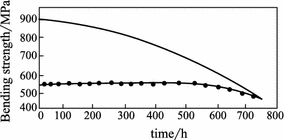
Effect of thermal aging on the bending strength of the CF/Thermid IP-600 composites. —Tested in air ambient;
 tested at 288 °C
Fig. 3.99 
Effect of thermal aging on the interlaminar shear strength of the CF/Thermid IP-600 composites. —Tested in air ambient;
 tested at 288 °C
Using 6FDA to replace BTDA, the generated Thermid AF-700 gives a T g of 95 °C and its cure onset and peak temperatures are 228 and 244 °C, respectively. The cure reaction heat is equivalent to that of Thermid MC-600, but its peak temperature range is wider. This means that the curing reaction of Thermid AF-700 is more consistent and its curing window is wider. The cured Thermid AF-700 resins have a T g of 350 °C and a thermal decomposition temperature of 500 °C.
Thermid AF-700 has very good dielectric performance. Figure 3.100 shows the dielectric performance of Thermid MC-600 and Thermid AF-700 at different frequencies. For Thermid AF-700, the dielectric constant and the loss factor increase as the curing time increases. The dielectric performance can be different at different frequencies. Compared with Thermid MC-600, the performance of Thermid AF-700 is better before and after curing [134].
Fig. 3.100 
Dielectric performance of acetylene-terminated polyimides. ⊕—Cold pressed, dielectric constant K; +—cold pressed, loss factor; △—cured, dielectric constant K; ▲—cured, loss factor; ○—post-cured, dielectric constant K; ●—post-cured, loss factor
-
(2)
Thermcon resin performances
Table 3.126 lists the physical properties of the Thermcon-1000 resins and includes the high reaction heat of Thermcon-1000. To avoid the thermal decomposition that may be induced during resin curing, a step curing procedure is required. A typical curing process will be 155 °C curing for 2 h and then at 200 °C for 94 h. In this way, insulating materials with very stable dielectric constants and loss factors as well as very good dielectric properties over a wide frequency range are obtained (Fig. 3.101).
Table 3.126 Thermcon 1000 physical performance Fig. 3.101 
Dielectric performance of Thermcon 1000
Cured Thermcon resins can undergo further high-temperature post-treatment and can be fabricated into conductive plastics with very stable performance under ambient conditions. After curing at 150 °C/2 h + 200 °C/1 h + 250 °C/1 h + 300 °C/50 h, its conductivity will depend on the post-treatment temperature and time, for example, after 600 °C post-treatment for 100 h, the conductivity of Thermcon 1000 can reach 5 S/cm.


 tested at 288 °C
 tested at 288 °C

3.7.3 Polyimide Composite Application
Polyimide composites have high specific strength and modulus as well as superior thermal–oxidation stability, which allow them to be used as replacements for metals at higher than 230 °C. Table 3.127 lists different resin composites with their service temperature ranges.
Polyimide composites in aircraft engine applications can significantly reduce the engine weight and increase the thrust–weight ratio. For example, polyimide composites are used extensively in aeronautical turbine engines. Engine parts made of polyimide composites include F404 by-pass air duct, CF6 core cap, F100 flap, YE-120 static blade, PLT-210 condenser case and the F110AFT fairing. The polyimide resin matrixes in these composite engine parts are PMR-15 and V-CAP-75. Some of them have been certified by airworthiness testing and are in service.
The F404 by-pass air duct was the first composite engine part made of T300 fabric/PMR-15. It is a coning cylinder with a diameter and length of 76 and 102 cm, respectively. The composite part weighs about 13 kg.
The processing molds for the F404 by-pass air duct are made of molding steel (Fig. 3.102). The mold is made during frame construction and installed on a support stand. The mold can be rotated on an axis shaft for easy lamination. The F404 by-pass air duct is manufactured by autoclave curing processing with curing parameters as follows:

Processing molds for F404 composite by-pass air duct
-
(1)
Apply vacuum at 13 kPa.
-
(2)
Heat to 204 °C at a rate of 23.5 °C/min
-
(3)
Hold for 12 min at 204 °C and then apply full vacuum.
-
(4)
Heat to 238 °C at a rate of 2–3 °C/min and apply pressure at 1.277 MPa.
-
(5)
Heat to 252 °C within 30 min, pressure at 1.277 MPa and then vacuum.
-
(6)
Hold for 30 min at 252 °C, pressure at 1.277 MPa and vacuum.
-
(7)
Heat to 307 °C at a rate of 1 °C/min, pressure at 1.277 MPa and vacuum.
-
(8)
Hold for 180 min at 307 °C, pressure at 1.277 MPa and vacuum.
-
(9)
Slowly cool to below 80 °C, remove pressure and vacuum.
After being released from the mold, the part is inspected by C-scan. Both the delamination and void content are lower than 3%. After static and operational testing, the part can be put into service. Compared with the Ti alloy by-pass air duct, the F404 composite part weighs 15–20% less and its cost is 30–50% lower [136, 137].
Although polyimide composites have obvious weight-saving advantages for airplane engines and enhance engine performance, for several reasons polyimide composites are still in small scale trials before use in airplane engines. Airplane engines are flight power devices and very high reliability requires very mature materials. As new materials, especially high-temperature-resistant polyimide composites, both experience and accumulated data are still insufficient. For small and complex composite engine parts, there are currently no reliable nondestructive inspection methods available. Additionally, engine parts require a higher service temperature than other airplane parts, and for high-temperature-resistant polyimide composites, the application ranges are limited to the cool ends of engines and to external parts. Finally, the market requirements for airplane engines are limited, and engine parts are produced in small volumes and have complex shapes and structures resulting in high production costs for engine composite parts.
Apart from their application in airplane engines, polyimide composites have been also applied in other airplane parts, for example, the ice-proof air pressure pipe system in the B747, the flap in the F-15 jet, etc.
In the B747, Ti alloy pipes were previously used and were 200 kg in total weight. These pipes have varied diameters and were required to meet the following conditions:
-
(1)
Pressure resistance: 0.5 MPa.
-
(2)
Max. service temperature: 232 °C.
-
(3)
Max. air flow: 12.4 m3/s.
-
(4)
Service term: 50,000 h.
For the service temperature and term, common composites do not meet these requirements and carbon-reinforced PMR-15 polyimide composites were selected. After replacing the Ti alloy pipes with the composites, the ice-proof air pressure pipe system in an airplane weigh 125 kg less, and the weight reduction is thus 35% or more [138].
(Translated by Jianmao Tang)
References
Chen XB (2000) Development of advanced polymer composites. J Aeronaut Mater 20(1):46–54 (in Chinese)
Chen XB (2003) Development and applications of advanced polymer matrix composites. J Aeronaut Mater 23(suppl):198–204 (in Chinese)
Chen XB, Zhang BY (2009) Application and development of advanced polymer matrix composites. Mater China 28(6):2–12 (in Chinese)
Du SY (2007) Advanced composite materials and aerospace engineering. Acta Mater Compos Sinica 24(1):1–2 (in Chinese)
Chen XB et al (1999) High performance phenolic resin. Chemical Industry Press, Beijing (in Chinese)
Yin RZ (1990) Phenolic resin and its application. Chemical Industry Press, Beijing (in Chinese)
Shanan ZM (1994) Thermosett Resin 15(3):27 (in Chinese)
Ren GG (1993) A new generation of phenolic resin and its composites. China FRP Industry Association, Beijing (in Chinese)
Jiang LX et al (1990) Heat resistant polymer. Press of University of Electronic Science and Technology of Chengdu, Chengdu (in Chinese)
Regina-Mazzuca Alba M, Fong Ark W, Jones Thomas R (1982) Novel process for the production of particulate phenolic resins. Ind Eng Chem Prod Res Dev 21:139
Brode GL, Kopf PW, Chow SW (1982) Phenolic thermospheres. Chemical design and principles. Ind Eng Chem Prod Res Dev 21:142
Yang YG et al (1988) Study on reaction kinetics of suspension polymerization of phenolic resin. J Beijing Univ Chem Technol 3:33 (in Chinese)
Wang LC et al (1993) Resorcin modified phenolic resin to reduce its flame, smoke and toxicity. Polym Mater (2):49 (in Chinese)
Bian JX (1991) Development of molding technology of phenolic resin. New Chem Mater 3:21 (in Chinese)
Phenolic Resin. Insulating Material and Technology Committee (1993) (in Chinese)
Pei DF (1996) Research on synthesis and ring-opening polymerization of benzoxazine-precursor of a new phenolic resin. Dissertation for Doctor’s Degree of Sichuan University (in Chinese)
Lu ZJ (1995) Dissertation for Master’s Degree of Sichuan University (in Chinese)
Kang YJ et al (1996) New type phenolic resin and its process development. GRP/Compos Mater 2:43 (in Chinese)
Pei DF et al (1994) Synthesis and modification of high performance phenolic resin. New Chem Mater 10:12 (in Chinese)
Xiao CR et al (1997) Study on performance of composite material based on FB resin (in Chinese)
Liu XH et al (1997) Study on friction materials based on heat resistant phenolic resin containing molybdenum. Eng Plast Appl 3:30 (in Chinese)
Lu ZJ et al (1995) Study on ring opening polymerization of composites materials based on phenolic resin—preparation of laminate of MDAPF1-EGF Glass Cloth. Eng Plast Appl 2:1 (in Chinese)
Lu FC (1993) Adhesive with high heat resistance. Science Press, Beijing (in Chinese)
Jiao YS (1994) Phenolic triazine resin, Fiber Reinf Plast/Compos (1):10 (in Chinese)
Liang GZ et al (1996) The BMI modifier—ally compounds. New Chem Mater 3:27 (in Chinese)
Canfield A, Clionton RG (1992) Improved ablative materials for the ASRM Nozzle. In: AIAA/SAE/ASEE 28th join propulsion conf and exhibit, Nashville, 3057
Chen MY (1990) Application status and prospect of advanced materials used in solid rocket motor of strategic missile. Aerosp Mater & Technol 4:1 (in Chinese)
ShangHai Chemistry College Lab (1979) Synth Resin, 208 (in Chinese)
Liu TD, Wang XC, Xu XP (1989) Thermosett Resin (2):38 (in Chinese)
Zou SO (1996) New Chem Mater (3):26 (in Chinese)
Shell Chemical Co (1988) Epon HPT Curing agent 1061-M, product data
Shell Chemical Co (1988) Epon HPT Curing agent 1062-M, product data
Schultz WJ et al (1988) Polym Prepr Am Chem Soc (1):136
Yao KD, Liu G (1992) Thermosetti Resin (3):52 (in Chinese)
Sun QL (1990) Thermosett Resin (4):48 (in Chinese)
US Patent 3015648
US Patent 4707534
Lin SC, Pearce EM (1979) J Polym Sci 17.3095
US Patent 3910908
Ciba-Geigy (1984) Araldite PT810, product data
Ciba-Geigy (1987) Araldite MY 0510, product data
Ciba-Geigy (1983) Araldite MY 0510, product data
Ciba-Geigy (1987) Araldite MY 720, product data
Ciba-Geigy (1987) Araldite MY 721, product data
Ciba-Geigy (1990) Araldite MY 722, product data
Shell Chemical Co (1988) Techn Bull SC:875–888. Epon HPT Resin 1071
Shell Chemical Co (1988) Tech Bull SC:876–888.Epon HPT Resin 1072
Patel RD et al (1988) J Therm Anal 34:1283
US Patent 4002599
Fornes RE et al (1991) Polym. Prepr (2):40
Pyun E (1991) Sung CSP. Macromolecules 24:855
Eur. Patent 76584
Cheng P, Hang LJ (1996) Thermosett Resin (2):42 (in Chinese)
Sun YS, Yang W (1990) Thermosett Resin (3): 1 (in Chinese)
Lu HB, Fu ZL (1990) J Tsinghua Univ (5): 22 (in Chinese)
Zhong XJ (1992) Adhesives (5):11 (in Chinese)
Bucknall CB, Partridge IK (1986) Polym Eng Sci (26):54
Gilert AH, Bucknall CB (1991) Makrojol Symp 45:289
Bennett GS et al (1991) Polymer 9:1633
Wang HM, Yi XS (1992) Thermosett Resin (4):35 (in Chinese)
ICI Fiberite (1991) 977-2 Epoxy Resin
Ciba-Geigy Composite Materials. R6376, product data
Hercules. 8552 Epoxy Resin, product data
Li B, Tang BM (1996) 5228 research report (in Chinese)
Cheng QB (2003) J Aeron Mater (S1): (in Chinese)
Zhang FF (1995) J Mater Eng (5):3 (in Chinese)
Liang GZ, Gu YJ (1997) Bismaleimide Resin. Chemical Industry Press, Beijing (in Chinese)
Zhang BY, Li P, Chen XB (1998) Studies of modified BMI resin (I) the Influence of resin composition on the thermal and mechanical properties. J Mater Sci 33:5683–5687
Zhang BY, Chen XB, Li M et al (2002) Discussion on the compression strength after impact of carbon fiber reinforced BMI resin matrix composite. J Aeronaut Mater 22(1):36–40 (in Chinese)
Yi XS (2006) Progress of advanced composite. National Defense Industry Press, Beijing (in Chinese)
Houben-weyl (1952) Methoden der Organischen Chemie, Vol 8/3, Thieme, Stuttgart: 89 and 125
Grigat E, Putter R (1967) Chem A. (International edition) 6(2):206
Grigat E, Putter R (1963) (Farbenfabriken Bayer AG). German patent 1195764
Grigat E, Putter R (1963) (Farbenfabriken Bayer AG). German patent 1201839
Zhou ZHM (University of Leeds) (1993). WO 95/07309
Grigat E, Chem A (1972) Chem A (International edition) 11(11):949
Stroh R et al (1960) Angew Chem 72:1000
Martin D et al (1964) Angew Chem 76:303
Fyfe CA et al (1992) Macromolecules 25:6289
Lin SC, Elim P (1994) High performance thermosets, Hanser publisher, New York, p 68
Shimp DA (1986) Polym Mater Sci Eng 58:107
Barton JM et al (1991) Polym Bull 25:475
Osei-Owusu A et al (1991) Polym Eng Sci 31(22):1604
Shimp DA (Celanese Corporation) (1986) U.S.P. 4, 604, 453; U.S.P. 4, 608, 434
Woo EP et al (The Dow Chemical Company) (1985) U.S.P. 4, 528, 366
Oehmke RW et al (Minnesota Mining and Manufacturing Company) (1972) U.S.P. 3, 694, 410
Osei-Owusu A et al (1992) Polym Eng Sci 32(8):535
Osei-Owusu A et al (1991) Polym Mater Sci Eng 65:304
Shimp DA et al (1988) In: 33th International SAMPE symposium, March 7–10, 754
Shimp DA et al (1992) In: 33th International SAMPE symposium, March 9–12
Marie F, Grenier L et al (1995) Eur Polym J 31(11):1139
Morio G (1994) Plym Mater Sci Eng 71:621
Ian H et al (1994) Polym Mater Sci Eng 71:807
Fyfe CA et al (1995) J Polym Sci A: Plym Chem 33:1991
Carig, WM Jr (INTEREZ, Inc.) (1987) E.P.0, 269,412
Bogan WW et al (1988) SAMPE J 24(6):19
Shimp DA et al (1989) In: 34th international SAMPE symposium, May 8–11, 222
Shimp DA et al (1990) In: 35th international SAMPE symposium, April 2–5, 1045
Tanigaichi M et al (1977) U.S.P. 4, 022, 755
Delano CB et al (1979) NASA-CR-159724
Sung et al (1997) 6th SPSJ Internat Polym Conf 46 (preprints)
Korshak VV et al (1980) Vysokomol Soedin Ser A 22(8):1714
Bauer M et al (1987) Acta Polymerica 38(12):658
Monnerat GA et al (1989) International SAMPE Electron Conf Sec (4):132
Yang PC et al (1990) 35th International SAMPE Symposium, April 2–5, 1131
Almen G, et al (1990) 35th International SAMPE Symposium, April 2–5, 408
Bao JW et al (1998) First Asian-Australasian conference on composite materials, Oct 7–9
Yang HX, Liu JG, Chen JS et al (2006) Synthesis and properties of RMR-type polyimide composites with improved flexibility. J Aeronaut Mater 26(3):173–176
Zhao WD, Wang L, Dong B et al (2009) PMR-type polyimide matrix composites and their applications. Aerosp Mater & Technol 4:1–5
Mohamed O, Abdalla Derrick Deana et al (2002) Viscoelastic and mechanical properties of thermoset PMR-type polyimide-clay nanocomposites. Polymer 43:5887–5893
Conreur C, Francillette J, Laupretre F et al (1997) Synthesis and processing of model compound of PMR-15 resin. J Polym Sci A: Polym Chem 35(1):123–136
Ding YH (2011) Polymerization approach for polyimide preparation. Chem Intermed 5:36–43
Allred RE, Wesson SP, Shin EE (2003) The influence of sizings on the durability of high-temperature polymer composites. High Perform Polym 15(4):395–419
Bowman CL, Suaer JK, Thesken JC (2001) Characterization of graphite fiber/polyimide composites for m applications. Int SAMPE Symp Exhib (Proceedings), 46(2):1515–1529
Ahn MK, Stringfellow TC, Bowles KJ (1993) Investigation of stable free radicals in polyimides using EPR spectroscopy. Mater Res Soc Symp Proc 305:217–227
Morgan RJ, Shin EE, Lincoln J (2001) Overview of polymer matrix composites performance and materials development for aerospace applications. SAMPE J 37(2):102–107
Pater Ruth H, Curto Paul A (2007) Advanced materials for space applications. Acta Astronaut 61(11–12):1121–1129
Chen JS, Zuo HJ, Fan L et al (2006) Development of high temperature polyimide. Aerosp Mater & Technol 2:7–12
Yang SY, Gao SQ, Hu AJ et al (2000) Progress in high temperature polyimide matrix resins and carbon fiber reinforced composites. Aerosp Mater & Technol 1:1–6
Chen XB, Fu Y, Shen C et al (1998) Study on LP-15 non-MDA polyimide composite. Acta Mater Compos Sinica 15(1):7–13
Tandon GP, Pochiraju KV, Schoeppner GA (2006) Modeling of oxidative development in PMR-15 resin. Polym Degrad Stab 91(8):1861–1869
Tandona GP, Pochirajub KV, Schoeppnerc GA (2008) Thermo-oxidative behavior of high-temperature PMR-15 resin and composites. Mater Sci Eng, A 498:150–161
Tan B, Xiaosu YI (2001) High-temperature polyimide composites and its application in aeronautical engine. J Aeronaut Mater 12(1):55–62
Hou H, Wilkinson SP, Johnston NJ et al (1996) Processing and properties of IM7/LARCTM-RP46 polyimide composites. High Perform Polym, December, 89(4):491–505
Tiwari SN, Srinivansan K (1991) Toughening of PMR composites by semi-interpenetrating networks. NASA Report, NASA-CR-189468
Johnston NJ, Srinivasan K, Pater RH (1992) Toughening of PMR composites by gradient semi-interpenetrating networks. 37th Int SAMPE Symp Exhib, 37:690–704
Delvigs P (1985) PMR polyimides from solutions containing mixed endcaps. NASA Conference Publication, 23–24
Hurwitz FI, Daniel Whittenberger J (1984) Effect of a coating on the thermo-oxidative stability of Celion 6000 Graphite Fiber/PMR-15 polyimide composite. Compos Technol Rev 5(4):109–114
Mitrovic Milan, Carman Greg P (1996) Effect of fatigue damage in woven composites on thermo-mechanical properties and residual compressive strength. J Compos Mater 30(2):164–188
Delaney E, Riel F, Vuong T et al (1992) Preliminary physical, mechanical and toxicological properties of a benign version of the PMR-15 polyimide resin system. SAMPE J 28(1):31–35
Koenig JL, Shields CM (1985) Specroscopic characterization of acetylene-terminated sulfone resin. Polym Sci: Polym Phys Ed 23(5):845–859
Landis AL, Naselow AB (1985) Improved processible acetylene-terminated polyimide for composites. NASA Conference Publication
Huang WX, Wunder SL (1994) FTIR investigation of cross-linking and isomerization reactions of acetylene-terminated polyimide and polyisoimide oligomers. J Polym Sci, B: Polym Phys 32(12):2005–2017
Wu LY (2005) The high performance/high temperature polymer an overview (V) polyimides oligomer terminated with reactive groups and its curing process. Thermosett Resin 20(5):41–47
Bott RH, Taylor LT, Ward TC (1986) Cure chemistry of acetylene-terminated polyimides. Am Chem Soc (Polymer Preprints, Division of Polymer Chemistry) 27(2):72–73
Mcdanels DL, Serafini TT, Dicarlo JA (1985) Polymer, metal, and ceramic matrix composites for advanced aircraft engine applications, N86-13407
Pratt RD, Wilson AJ (1985) Fabrication process of a high temperature polymer matrix engine duct, N86-11620, 401–407
Tan B, YI XS (2001) High-temperature polyimide composites and its application in aeronautical engine. J Aeronaut Mater 12(1):57–62
Author information
Authors and Affiliations
Corresponding author
Editor information
Editors and Affiliations
Rights and permissions
Copyright information
© 2018 Chemical Industry Press, Beijing and Springer Nature Singapore Pte Ltd.
About this chapter

Cite this chapter
Chen, X., Bao, J., Shen, C., Zhang, B., Xu, Y., Shen, Z. (2018). Polymer Matrix Materials. In: Yi, XS., Du, S., Zhang, L. (eds) Composite Materials Engineering, Volume 1. Springer, Singapore. https://doi.org/10.1007/978-981-10-5696-3_3
Download citation
DOI: https://doi.org/10.1007/978-981-10-5696-3_3
Published:
Publisher Name: Springer, Singapore
Print ISBN: 978-981-10-5695-6
Online ISBN: 978-981-10-5696-3
eBook Packages: Chemistry and Materials ScienceChemistry and Material Science (R0)