
Abstract
Esophagectomy is the best curative therapy for cancers of the esophagus and esophagogastric junction. In an effort to reduce the frequency of postoperative complications, minimally invasive techniques for esophagectomy have been developed. Our method for performing a modified Ivor Lewis resection with a cervical anastomosis begins with the thoracoscopic portion that utilizes three ports and a 5 cm access incision in the right chest. The esophagus is mobilized into the neck, and a complete nodal dissection is performed to the level of the azygos arch. Then the abdominal portion is performed using five ports. The stomach is mobilized, preserving the right gastroepiploic vessels and dividing the short gastric and left gastric vessels. A gastric emptying procedure is sometimes performed, followed by creation of a gastric tube. A feeding jejunostomy is placed using Seldinger technique. The gastric tube is sutured to the specimen. The left neck is opened while the laparoscopic portion is being completed. The esophagus is retrieved through the neck, the gastric tube is drawn into the neck incision and the esophagus is divided. A side-to-side anastomosis is created using a linear stapler for the back wall and suturing the front wall. This approach is suitable for most patients with esophageal cancer, including those who have undergone induction therapy. Immediate results are similar to or better than those reported for open operations.
The corresponding author of section 13.1 is Mark K. Ferguson, Email: mferguso@surgery.bsd.uchicago.edu (✉);
The corresponding author of section 13.2 is C.S. Pramesh, Email: prameshcs@tmc.gov.in (✉);
The corresponding author of section 13.3 is Zuli Zhou, Email: zuli@sina.com (✉);
The corresponding author of section 13.4 is C.S. Pramesh, Email: prameshcs@tmc.gov.in (✉);
The corresponding author of section 13.5 is C.S. Pramesh, Email: prameshcs@tmc.gov.in (✉);
The corresponding author of section 13.6 is Jianfeng Li, Email: drlijf@vip.sina.com (✉)
Access provided by CONRICYT-eBooks. Download chapter PDF
Keywords
1 Introduction and Technique
1.1 Background
Esophagectomy is the best means of achieving local tumor control in patients with esophageal cancer, and arguably is the only treatment that reliably offers the possibility of cancer cure, especially in patients with early stage disease. Traditional approaches to esophagectomy, including open transthoracic resection and transhiatal esophagectomy, have demonstrated similar outcomes for most complication categories and similar long-term survival. The high rates of postoperative complications reported for these techniques, including operative mortality, have prompted the development of minimally invasive techniques for esophagectomy. The potential advantages of minimally invasive esophagectomy (MIE) include reduced postoperative pain, less activation of inflammatory mediators, reduced perturbation of pulmonary function, shortened length of hospital stay, and faster return to full activity.
1.2 Indications
MIE is an appropriate consideration for most patients who require esophagectomy for either benign or malignant disease. Potential technical advantages of the technique include improved visualization for lymph node dissection and preservation of recurrent laryngeal nerves, and reduced blood loss and requirements for perioperative transfusion. However, considerable expertise in advanced minimally invasive techniques, including intracorporeal suturing and knot tying, is necessary to take full advantage of these potential advantages. MIE should not be undertaken by surgeons without substantial experience in open esophageal surgery. A team of surgeons, nurses, anesthesiologists, and critical care specialists is required to achieve optimal outcomes, and the learning curve for the operation is often difficult and prolonged. It is estimated that 50–100 procedures are required before a stable, low rate of complications is achieved. Complications that may occur more often with MIE include airway injury, herniation of abdominal contents through the esophageal hiatus, increased tension on cervical anastomoses leading to a higher rate of anastomotic leak, and jejunostomy feeding tube dislodgement. Increasing experience with MIE has led to methods for reducing the incidence of these complications.
1.3 Patient Selection
There are few definite contraindications to MIE. Most patients with esophageal cancer in our practice have undergone induction chemotherapy and radiation therapy. These patients require a careful preoperative assessment of their physiologic status to ensure adequate pulmonary function (spirometry and diffusing capacity), adequate performance status, and satisfactory nutritional status. At times it is necessary to put off MIE until the patient’s status has improved after completion of induction therapy. If the interval between completion of radiation therapy and possible surgery grows too long, open esophagectomy, especially for the thoracic portion of the operation, may be a better option. Other contraindications include prior major ipsilateral thoracic surgery, a frozen abdomen, and possibly an indwelling esophageal stent, which inhibits adequate displacement of the esophagus to permit adequate visualization.
The modified Ivor Lewis MIE with cervical anastomosis is applicable to patients with disease in any location other than those in whom an extended gastrectomy is planned, such as those with Siewert III tumors. It is most suitable for patients with disease in the middle and upper thirds of the thoracic esophagus, in whom a 5 cm margin on the esophagus from the proximal margin of gross tumor may otherwise be difficult to achieve.
1.4 Operative Technique
A bowel prep is performed the day prior to surgery to reduce intraluminal intestinal contents. Antibiotic bowel preparation is not required. An epidural catheter is used routinely to assist with postoperative pain management, and may help reduce the incidence of postoperative supraventricular arrhythmias. Arterial line monitoring is standard, but placement of a central venous line for monitoring fluid status is not usually necessary. Prophylactic subcutaneous heparin and lower extremity intermittent compression devices (ICDs) are used in all patients. A left-sided double lumen endotracheal tube is placed. In morbidly obese patients or those who have a history of venous thromboembolic disease, a temporary inferior vena cava (IVC) filter is placed after induction of general anesthesia.
1.4.1 Thoracic Portion
The patient is placed in the left lateral decubitus position. The right lung is isolated. A 5 mm port is placed in the anterior axillary line in the ninth interspace for inspection of the pleural space; this is eventually upsized to a 12 mm port. A 5 mm port is placed in the posterior axillary line at the level of the diaphragm, and a 5 mm port is placed medial to the scapular tip, at the level of the arch of the azygos vein. A 5 cm access incision is created in about the fourth interspace in the anterior axillary line; no rib spreading is performed. This incision is often used to accommodate two instruments simultaneously. A heavy silk suture is placed through the tendinous portion of the diaphragm and is brought through a low intercostal space anteriorly to retract the diaphragm away from the esophageal hiatus.
The lung is retracted away from the esophageal hiatus. The telescope is placed through the posterior inferior port, and the other inferior port and the superior 5 mm port are used for the primary surgeon’s instruments. A 30° 5 mm telescope is used routinely. The pleura is divided on either side of the esophagus to the azygos arch, sparing the azygos vein and thoracic duct. The esophagus is dissected circumferentially at the level of the inferior pulmonary vein, preserving the contralateral pleura, and is surrounded with a Penrose drain, which is used to retract the esophagus during the subsequent dissection. The esophagus and all adjacent soft tissues are dissected from the esophageal bed from the hiatus to the azygos arch. All periesophageal lymph nodes are taken with the specimen other than the subcarinal (level 7) lymph nodes, which are dissected separately.
The azygos vein arch is divided with a linear cutting stapler placed through the anterior inferior port site. The pleura overlying the esophagus is divided from the level of the azygos arch to the thoracic inlet. The esophagus is dissected superiorly directly on its wall into the neck. Any enlarged lymph nodes are removed from above the level of the azygos vein, taking care to preserve the recurrent laryngeal nerves. The Penrose drain surrounding the esophagus is pushed into the neck to facilitate retrieval of the esophagus through the subsequent cervical incision. One or two chest tubes are placed through the inferior port sites to the apex of the hemithorax. The lung is re-expanded as the remaining two port sites are closed in layers.
1.4.2 Abdominal Portion
The patient is reposition supine position with both arms tucked against the torso to permit access to the neck. The surgeon stands on the patient’s right side while the first assistant and camera operator stand on the patient’s left. Ports are placed somewhat caudal to those for antireflux procedures to facilitate gastric mobilization, gastric emptying procedure, and tube jejunostomy. Initial peritoneal access is gained just to the left of midline approximately 16 cm below the xiphoid. For individuals who have had prior upper midline incision, access is obtained just lateral to the right midclavicular line four fingerbreadths below the costal margin. A 45° laparoscope is routinely utilized for the entire abdominal portion of the procedure. A Nathanson liver retractor (Cook Medical; Bloomington, IN) is inserted through a 5-mm subxiphoid incision and is secured using a self-retaining holder. A 15-mm dilating port is placed in the right medial mid-abdomen to accommodate the 4.8 mm staple-height cartridges used to create the gastric conduit, and a 5 mm left upper abdominal port site is ultimately used as the jejunostomy tube site.
The gastrohepatic ligament is widely opened and celiac axis lymphadenectomy is performed. Circumferential dissection of the origin of the left gastric pedicle is performed, and the pedicle is transected with a 60–2.5 mm stapler with bioabsorbable buttressing material.
The gastrocolic omentum is opened and the lesser sac entered at the level of the proximal antrum lateral to the gastroepiploic arcade. Dissection proceeds proximally using a bipolar sealing device or ultrasonic coagulating shears, with division of the short gastric vessels and complete mobilization of the fundus to the left crus. The cephalad aspect of the dissection is facilitated by division of the posterior gastropancreatic adhesions. Dissection then proceeds distally along the gastroepiploic arcade near the origin of the right gastroepiploic vessels, requiring posterior mobilization of the antrum and pylorus to the level of the gastroduodenal artery. A formal Kocher maneuver is performed. A gastric emptying procedure (pyloroplasty or pyloromyotomy) is typically performed.
The neurovascular arcade along the lesser curve of the stomach is divided using a bipolar sealing device or vascular stapler at the level of the incisura. The gastric conduit is created using multiple firings of a thick tissue roticulating endoscopic stapler (60–4.8 mm), with the assistant providing gentle retraction to allow the stapler to be oriented parallel to the greater curvature. The conduit measures approximately 5 cm in diameter.
The remaining circumhiatal attachments and distal esophagus are mobilized. The proximal aspect of the conduit staple line is reapproximated to the specimen using a short (1.5–2 cm) running suture to allow the conduit to be pulled up into the chest in appropriate orientation. The hiatus is assessed at this time, and if it will not easily accommodate the width of the conduit, the right crus is divided to the necessary extent.
The ligament of Treitz is identified and a site 40–50 cm from the ligament is selected for the feeding tube. Two 35 cm semicircular pursestring sutures are placed in the antimesenteric aspect of the jejunal loop. The 5 mm left lateral port is removed, and the tails of the sutures are brought out through the fascia and the port site. While maintaining tension on the proximal suture, the feeding tube is placed using Seldinger technique with care taken to ensure proper distal orientation of the tip. The sutures are then tied, affixing the bowel loop to the anterior abdominal wall and providing circumferential serosal coverage of the tube entry site.
1.4.3 Anastomosis
The left neck is opened transversely from the midline to a site between the heads of the sternocleidomastoid muscle, just below the level of the cricoid cartilage. Dissection is carried between the carotid sheath and the strap muscles to the prevertebral plane, taking care to avoid injuring the recurrent laryngeal nerve. The Penrose drain surrounding the esophagus is used to pull the esophagus into the wound.
The lungs are permitted to collapse to eliminate tension while the stomach is transposed. The specimen, which is attached to the gastric tube, is drawn through the mediastinum and into the neck, pulling from above and pushing from below, taking care not to injure the serosa or the gastric blood supply. The specimen is divided from the gastric tube. The esophagus is divided with a linear cutting stapler to provide an adequate margin from the tumor and sufficient length to perform the anastomosis. The specimen is removed.
The gastric tube is positioned posterior to the esophagus with the greater curvature facing anteriorly. Inspection verifies the absence of twisting of the gastric tube. Stay sutures of heavy silk are used to position the esophageal stump at least 5 cm below the tip of the gastric tube. Small openings are created in the stapled end of the esophagus and in the adjacent wall of the stomach near the greater curvature, as far from the lesser curvature suture line as possible. A 45 mm cartridge with 3.5 mm staples is inserted, one end into the gastrotomy and one end into the open esophagotomy, and is fired, creating a V-shaped opening between the stomach and esophagus that forms the back wall of the anastomosis. A nasogastric tube is positioned across the anastomosis to the level of the hiatus or just below. The anterior wall of the anastomosis is then sutured or stapled. If there is redundant omentum, this is sutured over the anastomosis to reinforce it.
The gastric tube is pulled inferiorly to eliminate redundancy and is sutured in two to three places to the esophageal hiatus to prevent herniation of abdominal contents. The liver retractor is removed, and after exsufflating the abdomen and removing the ports, the skin incisions are closed using subcuticular sutures. The skin of the neck wound is closed; no neck drains are typically required.
1.4.4 Postoperative Management
The patient is awakened, extubated in the operating room, and transported to the intensive care unit where vigorous pulmonary toilet exercises are begun. The patient is usually ambulated the day following surgery. Enteral tube feedings are begun slowly the morning of postoperative day 1 and are gradually increased as tolerated. The chest tubes are removed when the drainage is relatively clear and of moderate quantity, typically on postoperative day 3. The epidural catheter is removed and the patient is switched to intravenous and enteral pain medicine. The nasogastric tube is removed with the patient exhibits bowel activity by passing gas or having a bowel movement, typically on postoperative day 4 or 5. No swallow studies are performed routinely. A clear liquid diet is then started, and the patient subsequently is advanced to a full liquid diet, at which time the tube feedings are changed so that they are administered only for 12 h at nighttime but are maintained at the same hourly rate. The patient is typically discharged on postoperative day 6–8.
1.5 Discussion
Minimally invasive esophagectomy is challenging even for the most advanced minimally invasive surgeon. Ideally, technical skills encompassing laparoscopic and thoracoscopic specialists are used in combination to achieve the best possible results. Having a management algorithm encompassing the preoperative evaluation, intraoperative management, and postoperative care of MIE patients, along with frequent assessment of results and reassessment of the algorithm, permits adjustments as necessary if adverse outcomes are experienced. Even with these steps, the learning curve for MIE is appreciable.
The potential benefits of MIE are increasingly recognized. The feasibility of MIE as a safe and oncologically sound procedure has been proven. Whether it has oncologic equivalence to open operations remains to be seen. Additional information from prospective, randomized trials may help in clarifying the role of MIE in the management of esophageal cancer.
2 Laparoscopic Gastric Mobilization and Creation of Gastric Tube
2.1 Technical Points (or Tips)
Laparoscopic gastric mobilization and creation of gastric tube is usually done after the thoracoscopic mobilisation of the esophagus while doing a McKeown esophagectomy. Laparoscopic gastric mobilisation may also be the initial procedure in a minimally invasive Ivor-Lewis or transhiatal esophagectomy. The procedure may be performed totally laparoscopically or with the creation of a minilaparotomy.
The key points to remember are:
-
Minimal/atraumatic handling of the gastric conduit
-
Maintenance of the blood supply by avoiding injury to the right gastro-epiploic arcade
-
Adequate mobilization to enable tension free anastomosis
The following difficulties may be faced:
-
The omentum may be fused, especially in obese patients making it difficult to visualise the right gastro-epiploic arcade.
-
Bulky lymph nodes present around the left gastric, hepatic and splenic arteries may make the D2 lymphadenectomy tedious.
-
Care must be taken to identify and preserve an aberrant/ replaced left hepatic artery arising from the left gastric artery.
-
Splenic injury may occur if dissection of short gastric vessels is carried out close to the splenic hilum.
2.2 Anatomical Landmarks
A thorough knowledge of the surgical anatomy, especially of the celiac axis and its branches supplying the stomach is essential for laparoscopic gastric mobilization.
-
The blood supply of the gastric conduit is based mainly on the right gastro-epiploic artery, a branch of the gastro-duodenal artery, which in turn arises from the common hepatic artery, a direct branch of the celiac axis. The right gastro-epiploic artery runs in the greater omentum along the greater curvature from the pylorus towards the fundus (right to left).
-
The left gastro-epiploic artery, a branch of the splenic artery and short gastric arteries, which also arise from the splenic artery and supply the upper part of the greater curvature and the fundus.
-
The right gastric artery, a branch of the hepatic artery proper and the left gastric artery, which is a direct branch from the celiac supply the lesser curvature.
-
The left gastric, right gastric and right gastro-epiploic veins drain into the portal vein whereas the left gastric epiploic and short gastric veins drain into the splenic vein.
2.3 Operating Procedure
2.3.1 Ports, Pneumoperitoneum, Instruments
-
We position the patient supine with arms by the side and a roll is placed under the scapula for extension of the neck to aid in neck extension and dissection.
-
The patient is given a reverse Tredelenberg position. The surgeon stands to the right of the patient, the assistant to the left with monitors on either side of the patient. An alternative position is with the operating surgeon standing between the abducted thighs of the patient.
-
We place five ports for the laparoscopic gastric mobilization (Fig. 13.1) – an umbilical port for the camera, an epigastric port for liver retraction, two dissecting ports for the surgeon on the right (one subcostal and one at the level of the umbilicus) in the mid-clavicular line and one assistant port on the left lateral abdominal wall.
Fig. 13.1 
The abdominal port positions are as shown in the figure. The surgeon operates using the right sided ports while the assistant uses the left port
-
After insertion of the camera port by the open method, pneumoperitoneum is created and an inspection of the liver (Fig. 13.2), peritoneal surfaces and pelvis is carried out to rule out any metastases. The other four ports are placed under vision.
Fig. 13.2 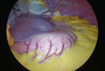
A preliminary inspection of the liver and peritoneal surfaces is done to rule out metastases


2.3.2 Mobilisation
-
Mobilisation is started along greater curvature after visualizing the right gastro-epiploic arcade. The gastrocolic omentum is divided using harmonic shears (Fig. 13.3). We prefer to start the mobilization midway in the gastrocolic omentum (where the omentum is thinnest, enabling the gastroepiploic arcade to be visualized without difficulty) and progress initially towards the fundus and subsequently towards the pylorus.
Fig. 13.3 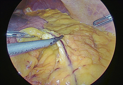
The gastrocolic omentum is serially divided at a safe distance from the right gastro epiploic arcade taking care to avoid injury to the arcade
-
After creating a window in the gastrocolic omentum, the mobilization continues towards the fundus, initially dividing the posterior peritoneal reflection over the superior border of the pancreatic body and tail (Fig. 13.4) and subsequently sealing and dividing the posterior short gastric vessels (Fig. 13.5).
Fig. 13.4 
The posterior peritoneal reflection is then divided to further free the stomach
Fig. 13.5 
The short gastric arteries are carefully sealed and divided, taking extreme care to avoid bleeding
-
Next, the short gastric vessels from the splenic artery are carefully sealed and divided (Fig. 13.6). The short gastric vessels can cause troublesome bleeding, sometimes necessitating conversion to open surgery and/or splenectomy if not visualized and coagulated well. It is important to be patient while coagulating these vessels and divide them only after complete sealing to prevent this complication, especially when the omentum between the greater curve and the splenic hilum is very short.
Fig. 13.6 
The posterior short gastric vessels need to be separately sealed and divided
-
The mobilization of the stomach on the right should be carried out till the pylorus to ensure adequate length. Care must be taken to avoid injury to the right pastor epiploic pedicle at this level (Fig. 13.7).
Fig. 13.7 
The division of the gastrocolic omentum is continued to the right up to the level of the pylorus, preserving the right gastro epiploic pedicle
-
Care must be taken to identify and preserve the entire right gastroepiploic artery throughout this mobilization to avoid ischemia of the gastric conduit.
-
The lesser omentum is opened after retracting the liver and serially divided starting from the lesser curvature of the stomach and progressing towards the hiatus (Fig. 13.8). Any accessory/replaced left hepatic arteries arising from the left gastric should be identified and preserved.
Fig. 13.8 
The gastrohepatic omentum is divided, taking care to identify and preserve any aberrant hepatic arteries that are occasionally seen
-
The above maneuver exposes the left gastric vessels which can be identified by lifting the lesser curvature upwards. The left gastric vessels are then dissected (Fig. 13.9) along with the adjacent lymph nodes.
Fig. 13.9 
The left gastric vein and artery are dissected, along with the lymph nodes around them
-
A D2 lymphadenectomy along the hepatic, left gastric, splenic and celiac vessels is completed now (Fig. 13.10).
Fig. 13.10 
The hepatic, left gastric and splenic group of lymph nodes are dissected off the named vessels
-
The left gastric vessels are now ligated (Fig. 13.11) using hemolok clips (our preference) or a vascular stapler and then divided.
Fig. 13.11 
The left gastric vein and artery are ligated using clips
-
The dissection is then carried out posteriorly upto the hiatus; division of the gastrohepatic omentum and phrenoesophageal ligament should not be completed at this stage to avoid the escape of gas and loss of pneumoperitoneum (Fig. 13.12).
Fig. 13.12 
The dissection is continued up to the hiatus without opening it to prevent escape of pneumoperitoneum
-
After ensuring that the entire stomach has been mobilized from the pylorus to the fundus, the hiatal dissection is initiated. The phrenoesophageal ligament and crura are dissected and the gastroesophageal junction is freed from the all the attachment to the retroperitoneum, spleen and crura. This is continued till the thoracic cavity is entered and the lower esophagus is visualized.


2.3.3 Creation of Stomach Tube
-
The stomach tube can be created either intracorporeally or extracorporeally through a small 5 cm minilaparotomy.
-
When the tube is being created intracorporeally, we start the stapling of the lesser curve at a predefined point (Figs. 13.13 and 13.14), usually at the junction of the left and right gastric artery branches.
Fig. 13.13 
The point on the lesser curvature of the stomach where the stomach tube creation is planned is marked
Fig. 13.14 
The first stapler is fired to fashion the stomach tube
-
We progressively form the stomach tube using serial staples, taking care to keep the stomach tube neither too broad nor too narrow (Fig. 13.15). The final staple is not fired from the abdomen to facilitate pulling up of the stomach tube along with the esophagus into the neck wound (Fig. 13.16).
Fig. 13.15 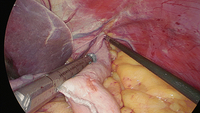
The stomach tube is created by serial firings of the stapler
Fig. 13.16 
The stomach tube is formed except for the last firing to maintain the connection between the specimen and the stomach tube
-
The neck is opened using a transverse incision (see section “Cervical Esophageal Anastomosis”) and the esophagus mobilized.
-
The esophagus with the stomach tube (connected by the last part of the stomach tube which remains intact) is then pulled through the posterior mediastinum (Fig. 13.17) into the neck wound and the final staple fired to complete the formation of the stomach tube.
Fig. 13.17 
The connection between the stomach tube and the specimen permit pulling of the stomach tube along the posterior mediastinum
-
When the stomach has been adequately mobilized, the pylorus will be seen just below the hiatal opening (Fig. 13.18) facilitating a tension free anastomosis in the neck.
Fig. 13.18 
The stomach tube is pulled up along the mediastinum; the pylorus reaches just below the hiatal opening to ensure a tension-free anastomosis at the neck
-
When the stomach tube is being created extracorporeally, we extend the 5 mm xiphisternal (liver retractor) port incision downward for about 5 cm, introduce a wound protector, and retrieve the full stomach with the mobilized esophagus into the abdomen wound.
-
The stomach tube is then created extracorporeally using serial stapling (Fig. 13.19), stutured to a tape and pulled into the cervical wound.
Fig. 13.19 
Extracorporeal stomach tube creation (all other steps are identical to the intracorporeal stomach tube formation)
-
The stomach tube is then anastomosed with the proximal esophagus in the neck using a triangulated stapled or a handsewn technique (see section “Cervical Esophageal Anastomosis”).


3 Laparoscopic Percutaneous Feeding Jejunostomy
3.1 Technical Points
Early initiation of enteral nutrition is preferred over parenteral nutrition for patients undergoing esophagectomy. Laparoscopic percutaneous feeding jejunostomy is a safe and simple technique that adds little to the morbidity and cost of managing patients with esophageal cancers undergone MIE. It facilitates optimization of nutrition in the perioperative period for these patients, especially in those receiving preoperative chemotherapy.
3.2 Anatomical Landmarks
Identifying the ligament of Treitz and locating the proximal direction of the bowl are crucial to the technical. A helpful anatomical note is that there is less mesenteric fat in the proximal small bowel compared to the ileum and the presence of “windows” between the mesentery and bowel wall suggests a proximal location.
3.3 Operating Procedure
-
1.
The bowel is grasped and run in one direction or the other until the ligament of Treitz is identified. When the ligament of Treitz is identified, a segment of small bowel about 20–30 cm distal is grasped and pushed to the abdominal wall to ensure that the bowel will move that far anteriorly without tension (Fig. 13.20).
Fig. 13.20 
A segment of small bowel is grasped and pushed to the abdominal wall to ensure that the free bowel is long enough
-
2.
An appropriate location for the jejunostomy is identified and marked on the antimesenteric surface of the small bowel. The 5 mm trocar incision in the left upper quadrant was chosen as the entry site of the jejunostomy tube on the abdominal wall. Loose Purse-string suture is made with 3-0 MERSILK® around the jejunostomy location (Fig. 13.21).
Fig. 13.21 
Loose Purse-string suture is made with 3-0 MERSILK® around the jejunostomy location
-
3.
The silk suture is taken out of the abdominal cavity with a latch needle. So the bowel can be pulled to the abdominal wall (Fig. 13.22a, b).
Fig. 13.22 
The silk suture is taken out of the abdominal cavity with a latch needle. The bowel is pulled to the abdominal wall then
-
4.
While retracting the small bowel with the T-Fasteners, an 18 gauge needle is passed through the center of the T-Fasteners into the jejunum. A guidewire is then passed through the needle distally into the jejunum and the needle removed. A split catheter sheath is then passed over the guidewire into the bowel, the guidewire removed, and the jejunostomy tube passed through the split catheter sheath into the jejunum. The split catheter sheath is removed and the T-fasteners are secured to hold the jejunum in place against the abdominal wall (Fig. 13.23).
Fig. 13.23 
The process of placing feeding tube
-
5.
A second purse-string suture is sewn with 3-0 MERSILK® at the distal part around the insertion site of the catheter into the jejunum. The silk suture is also taken out with a latch needle as step 3, but through a different puncture point (Figs. 24 and 25).
Fig. 13.24 
A second purse-string suture is sewn
Fig. 13.25 
The silk suture is taken out with a latch needle
-
6.
The two sutures are pulled tight and tied on the anterior abdominal wall (outside). This maneuver will attach the jejunum against the anterior abdominal wall securely. The suture will be closed at skin level. The jejunostomy tube is fixed using the fixing devices after confirming the tube is not blocked (Fig. 13.26).
Fig. 13.26 
The inner sight after the jejunostomy tube is fixed


4 Thoracoscopic Esophageal Mobilization
4.1 Technical Points (or Tips)
Thoracoscopic esophageal mobilization is an integral part of the McKeown three phase and the Ivor-Lewis esophagectomy procedures.
The key points to remember are:
-
Confirm operability before extensive esophageal mobilization to avoid esophageal necrosis in case of inoperability
-
Avoid injury to the tracheobronchial tree, descending thoracic and arch of aorta
-
Ligate the thoracic duct if injured, dissected or exposed
The following difficulties may be faced:
-
Lung collapse may be suboptimal either due to extensive lung adhesions or a smoker’s lung, making dissection difficult.
-
Meticulous dissection in the regions of the right and left recurrent nerve (RLN) lymph nodal groups is necessary to avoid temporary or permanent RLN paresis/palsy.
-
Care must be taken to identify and preserve an aberrantsubclavian artery arising from the descending thoracic aorta.
4.2 Anatomical Landmarks
Thoracoscopic esophageal mobilization is relatively straightforward as there are very few variations in the anatomical landmarks.
-
The blood supply of the thoracic esophagus arises primarily from direct branches of the descending thoracic aorta.
-
The upper half of the esophagus closely abuts the membranous wall of the trachea and the left main bronchus anteriorly.
-
The pericardium offers a good plane of dissection with the lower half of the esophagus anteriorly.
-
The horizontal part of the azygous vein with the bronchial artery forms the roof of a tunnel through which the esophagus courses (junction of the upper and middle thirds).
-
The thoracic duct runs vertically parallel to the vertical part of the azygous vein between it and the descending thoracic aorta, and crosses over to the left side at the level of the tracheal bifurcation.
-
The right RLN branches out from the right vagus nerve just after it crosses the right subclavian artery; the left RLN has a much longer course and is given off from the left vagus just after it crosses the aortic arch, and runs along the left tracheo esophageal groove
4.3 Operating Procedure
4.3.1 Ports, Pneumothorax, Instruments
-
We place the patient on the right edge of the operating table, in the left lateral position, with the operating surgeon standing posterior to the patient and the assistant standing anterior. Monitors are placed both anterior and posterior to the patient to facilitate good visualization for both the surgeon and the assistant.
-
The patient’s arms are raised and the table flexed (or ‘broken’) midway to avoid the hip getting in the way of the operating instruments. The upper (right) leg is flexed at the knee and a pillow placed between the thighs.
-
We place five ports for the thoracoscopic esophageal mobilization (Fig. 13.27) – a seventh/eighth space 10 mm camera port just anterior to the anterior axillary line, a 10 mm port just below the right nipple for lung retraction and a second retraction port between the camera and the lung retraction ports. We use two dissecting ports for the operating surgeon, a 5 mm port one finger breadth below and anterior to the tip of the scapula and a 5 or 10 mm port between this and the camera port. Sometimes, we use an axillary port in the second intercostal space in the mid axillary line to facilitate supracarinal lymphadenectomy.
Fig. 13.27 
Thoracoscopic port positions: the ports are placed in the shape of a gentle ‘U’ when viewed from below, as shown in the figure. A detailed description of the port positions is available in the text
-
We usually perform the thoracoscopic esophageal mobilization with right lung collapse using a left sided double lumen endotracheal tube. We have rarely needed a CO2 pneumothorax though it may be used to improve the lung collapse.

4.3.2 Mobilisation
-
We prefer to confirm that the growth is operable prior to mobilizing the rest of the esophagus – failure to do so has occasionally resulted in esophageal necrosis and leaks in case the growth is subsequently found to be stuck to the aorta or the tracheobronchial tree.
-
Two parallel incisions are made in the mediastinal pleura anterior (Fig. 13.28) and posterior to the esophagus at the level of the primary growth. We proceed with dissection on a deeper plane at this level circumferentially to confirm operability (Fig. 13.29).
Fig. 13.28 
The anterior mediastinal incision runs parallel to the anterior border of the esophagus at the level of the growth. Notice the traction from the forceps posteriorly and the counter-traction by the lung retractor anteriorly
Fig. 13.29 
The dissection is carried out deeper around the esophagus, separating it from the pericardium anteriorly. Again, notice the counter-traction offered by the lung retractor anteriorly against the pericardium, facilitating the dissection
-
Once the growth is confirmed to be free from the tracheobronchial tree and the aorta, we continue the mediastinal pleural incisions superior (Figs. 13.30 and 13.31) and inferior to the growth, separating the esophagus from these major structures. We use either a monopolar cautery hook or harmonic shears or bipolar Maryland for dissection. Direct branches from the aorta are adequately coagulated by the harmonic device or the bipolar forceps.
Fig. 13.30 
The esophagus is mobilized along its length infracarinally, dissecting it off the thoracic aorta and the aortic arch posteriorly
Fig. 13.31 
The esophagus is dissected off the carina and left main bronchus anteriorly, taking care to avoid injury to the posterior membranous wall
-
Extreme care is necessary while dissecting the esophagus off the tracheobronchial tree anteriorly (Fig. 13.31), especially as the posterior wall of the tracheobronchial tree is membranous.
-
The pericardium offers a good plane of dissection anterior to the lower half of the esophagus.
-
Care must be taken to avoid unduly exposing or injuring the thoracic duct which runs between the aorta and the vertical portion of the azygous vein. If the growth is advanced and is close to the thoracic duct, it may be resected to achieve a negative margin (Fig. 13.32). We have a low threshold for ligating the thoracic duct in case the duct is mobilized or exposed extensively (Fig. 13.33).
Fig. 13.32 
The thoracic duct can be included along with the esophagus to achieve a wider circumferential margin, especially if the growth is more advanced and involves the adventitia or pleura
Fig. 13.33 
The thoracic duct has to be securely clipped using locking or regular liga clips lower than the lowest point where it has been dissected to reduce the chances of a postoperative chyle leak
-
We then proceed with the supracarinal part of the esophageal mobilization. Similar to the infracarinal part, we take parallel cuts in the mediastinal pleura to expose the esophagus (Fig. 13.34). We then proceed with most of the periesophageal dissection posteriorly, which is a relatively avascular plane anterior to the vertebral body and the prevertebral fascia (Fig. 13.35). Next, we dissect anteriorly between the trachea and the esophagus, taking care not to injure the posterior membranous wall of the trachea (Fig. 13.36).
Fig. 13.34 
Similar to the pleural cuts in the infracarinal mediastinal pleura, parallel cuts are taken in the mediastinal pleura supra carinally to expose the upper esophagus
Fig. 13.35 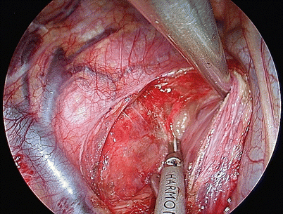
The plane posterior to the upper esophagus is relatively avascular and is easily developed
Fig. 13.36 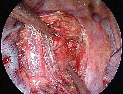
The plane between the upper esophagus and the trachea is now developed carefully, and the esophagus separated from the trachea
-
We prefer to preserve the azygous vein – bronchial artery complex to preserve the bronchial supply to the tracheobronchial tree unless the growth is located close to it. It is quite simple to dissect around the esophagus without ligating the azygous vein (Figs. 13.37 and 13.38). However, we ligate the complex while performing a supracarinal lymphadenectomy to improve access to the bilateral RLN group of lymph nodes.
Fig. 13.37 
The retroazygous part of the dissection can be done without dividing the azygous-bronchial artery complex, by careful dissection of this complex
Fig. 13.38 
The azygous vein is retracted upwards to allow complete dissection of the retroazygous esophagus


4.3.3 Lymphadenectomy
-
We perform a systematic mediastinal lymphadenectomy including the subcarinal, middle and lower para esophageal lymph nodes in all patients; in addition, we also perform supracarinal lymphadenectomy as part of three field lymphadenectomy and include the bilateral RLN groups, aorto pulmonary nodes and upper para esophageal lymph nodes.
-
The subcarinal nodes are best approached by dissecting just medial to the medial walls of the right and left main bronchi, taking care to avoid injury to the posterior wall of the bronchi. The entire subcarinal area needs to be cleared of all lymphatic and fibrofatty tissue (Fig. 13.39)
Fig. 13.39 
The subcarinal group of nodes should be completely dissected, laying bare the medial borders of the right and left main bronchi. Notice the left inferior pulmonary vein which serves as the deeper extent of circumferential esophageal mobilization
-
The right RLN group of nodes are identified by following the right vagus nerve superiorly where the right RLN curves around the right subclavian artery (Fig. 13.40). Care must be taken to avoid directly handling the nerve to avoid vocal cord paresis.
Fig. 13.40 
The right recurrent laryngeal group of nodes is dissected at the thoracic apex where the vagus nerve crosses the subclavian artery
-
We retract the tracheobronchial tree anteriorly to expose the left tracheobronchial angle – this exposes the aorto pulmonary group of lymph nodes for dissection (Fig. 13.41). Dissection in this region has to be extremely careful to avoid injury to the pulmonary artery. The left RLN can be identified in this region as it curves around the arch of the aorta.
Fig. 13.41 
The aorto-pulmonary group of nodes is dissected along the left tracheobronchial angle, and the left recurrent laryngeal nerve may be seen here as it curves around the aortic arch
-
The left RLN is dissected along the left paratracheal border in the groove between the trachea and the esophagus – exposure to this area is facilitated by retracting the trachea anteriorly using the fan retractor with the blades closed (Fig. 13.42). The left RLN group of nodes are carefully dissected taking care not to handle the nerve directly.
Fig. 13.42 
The left recurrent group of nodes are dissected along the left paratracheal border taking care not to directly handle the nerve
-
We confirm that the entire thoracic esophagus has been mobilized and is free from surrounding structures. We leave the supra diaphragmatic mediastinal pleura intact and do not open the hiatus to facilitate maintenance of the pneumo mediastinum during the laparoscopic part of the procedure.
-
The thoracoscopic ports are closed after ensuring hemostasis.


5 Cervical Esophageal Anastomosis
5.1 Technical Points (or Tips)
The esophagogastric anastomosis is a crucial part of esophagectomy and is an integral part of the McKeown three phase and the Ivor-Lewis esophagectomy procedures.
The key points to remember are:
-
Ensure minimal handling and maintain good vascularity of the stomach tube preserving the arcade along the greater curvature
-
Adequate mobilization of the esophagus at the neck and a avoid tension at the esophagogastric anastomosis
-
Either a stapled or a handsewn anastomosis may be done adhering to the basic principles of any gastrointestinal anastomosis
The following difficulties may be faced:
-
The length of the stomach tube may be inadequate to ensure a tension-free anastomosis in the neck.
-
A short right gastroepiploicic arcade may compromise the vascularity to the tip of the stomach tube.
5.2 Anatomical Landmarks
Careful attention to the anatomical landmarks in the neck facilitate this simple procedure and reduce complications from the cervical esophagogastric anastomosis.
-
The esophagus may be approached either between the two heads or medial to the medial head of the sternomastoid.
-
The esophagus is located posterior to the trachea and anterior to the prevertebral fascia and the vertebral bodies in the neck.
-
The carotid sheath containing the carotid artery and internal jugular vein is lateral to the esophagus and retraction of this structurelaterally improves access to the esophagus.
-
The middle thyroid vein drains into the internal jugular vein at this level and may require to be ligated
-
The left recurrent laryngeal nerve runs along the left tracheo esophageal groove and requires careful dissection to avoid vocal cord paresis.
5.3 Operating Procedure
-
We position the patient with the neck slightly extended (either by placing a roll below the shoulder blades or by ‘breaking’ the table) and turned to the right.
-
We take a transverse incision one finger breadth above and parallel to the medial half of the left clavicle and deepen it to the subplatysmal plane (Fig. 13.43); alternately a hockey-stick incision may be taken though we find it cosmetically less acceptable.
Fig. 13.43 
The skin incision is taken one finger-breadth parallel and above the medial half of the clavicle
-
The sternomastoid is retracted either between the two heads or medial to the medial head of the muscle.
-
Dividing the medial fibres of the strap muscles improves access to the cervical esophagus; the carotid artery and the internal jugular vein (Fig. 13.44) are gently retracted laterally to facilitate the exposure; the middle thyroid vein may need to be ligated.
Fig. 13.44 
The carotid artery and internal jugular vein are dissected and retracted laterally
-
The left recurrent laryngeal nerve is identified in the trachea esophageal groove and carefully preserved (Fig. 13.45).
Fig. 13.45 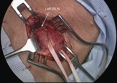
The left recurrent laryngeal nerve is identified and dissected in the tracheo esophageal groove
-
The plane posterior to the cervical esophagus is flimsy and avascular and should be developed first; subsequently the esophagus is dissected off the trachea anteriorly. The esophagus is then hooked up into the cervical wound (Fig. 13.46) and divided taking care to divide the mucosa 0.5–1 cm distal to the adventitial cut (Fig. 13.47).
Fig. 13.46 
The cervical esophagus is dissected off the trachea, and looped up into the neck incision
Fig. 13.47 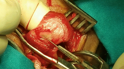
The esophagus is divided with the adventitial division about 0.5–1 cm above the mucosal division
-
If a minilaparotomy is planned to create the stomach tube (see Sect. 12.2), the esophagus and mobilized stomach are then pulled into the abdomen and through the minilap wound using a wound protector; if the stomach tube is being created intracorporeally, the esophagus and stomach tube are pulled into the neck.
-
The specimen is removed with completion of the stomach tube either through the minilaporotomy or the neck incision.
-
The stomach tube is brought up to the neck wound and the end of the tube is divided (Fig. 13.48); this gives the surgeon an opportunity to confirm adequate vascularity of the stomach tube.
Fig. 13.48 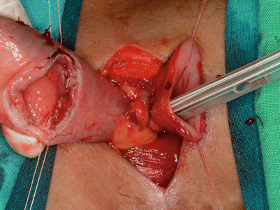
The stomach tube is brought up into the neck and divided with stay sutures on both the esophagus and the stomach tube
-
Stay sutures are taken in the esophagus and the end of the stomach, bringing them up into the incision like a double-barrel (Fig. 13.49).
Fig. 13.49 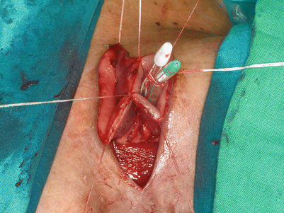
Two holding sutures are placed paramedian in the posterior wall of the stomach
-
A linear cutter is then introduced vertically into the lumen of the esophagus and the stomach up to the 3 cm mark (Fig. 13.50). The posterior layer of the anastomosis is created by firing a 55 or 60 mm staple (Figs. 13.51 and 13.52). Once the posterior layer of the anastomosis is complete, we place the nasogastric tube across the anastomosis (Fig. 13.53) in the stomach tube, with the tip midway in the chest.
Fig. 13.50 
The linear cutter is placed in the two ‘barrels’ of the esophagus and stomach tube, making sure that the nasogastric tube is not caught within the stapler
Fig. 13.51 
The posterior wall of the anastomosis is fashioned by firing the linear stapler. This opens up the anastomosis like a flower as seen in the figure
Fig. 13.52 
The nasogastric tube is placed across the anastomosis with the tip placed in the middle of the stomach tube for decompression
Fig. 13.53 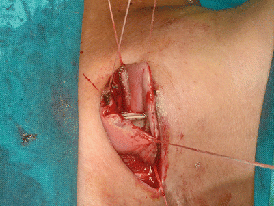
The anterior surface of the anastomosis is brought together using approximating sutures
-
The anterior layer of the esophago gastric anastomosis is brought together using approximating sutures (Figs. 13.54 and 13.55); the anastomosis is then completed using two more 55 or 60 mm staples with a triangulated technique (Figs. 13.56 and 13.57). If there is redundant omentum available, it may be loosely wrapped around the anastomosis.
Fig. 13.54 
A few additional sutures approximating the anterior wall of the anastomosis prepares it for the remaining two staples for the triangulated anastomosis
Fig. 13.55 
The first horizontal stapler is fired, completing half the anterior layer of the anastomosis
Fig. 13.56 
The second horizontal stapler completes the anterior layer of the anastomosis
Fig. 13.57 
The completed esophagogastric anastomosis is dropped back into the neck wound
-
Alternately, a handsewn anastomosis may be done, especially if the length of the cervical esophagus in the neck is too short to accommodate the linear stapler (especially for upper and middle third esophageal growths). Our preference here is to use a single layer of interrupted PDS sutures.
-
The main advantage of a triangulated stapled anastomosis over a handsewn one is that it creates a very roomy anastomosis, almost eliminating anastomotic strictures. Anastomotic leak rates have remained almost identical with the stapled and handsewn anastomosis in our hands.


6 Lymph Node Dissection
Squamous cell carcinoma is the most common pathological types of esophageal cancer in East Asia. The most common location of the tumor is middle esophagus, followed by the lower part and the upper part of it. Type of the lymph node metastasis of esophageal squamous cell carcinoma (ESCC) is significantly different from that of adenocacinoma in esophageal-gastirc junction. ESCC can either have upper mediastinal lymph node and cervical lymph node dissemination, or have abdominal lymph node metastasis. Postoperative local (regional lymph node) recurrence is the main cause for the failure of surgical treatment in ESCC. The number of lymph node dissected is related to the prognosis. Therefore, it is emphasized that the two-field lymph node dissection is crucial during MIE.
6.1 Mediastinal Lymph Node Dissection
6.1.1 Technical Points
Upper mediastinal lymph node dissection is an essential component of radical esophagectomy for esophageal squamous carcinoma. However, it is associated with significant morbidity and requires a great deal of skill when bilateral recurrent laryngeal nerves (RLNs) dissection is performed with minimally invasive surgery. Excellent exposure of anatomy is the key point during the lymph node dissection, and the following tips can be very helpful:
-
“Freestyle” posture: The patient is placed in a true left lateral decubitus position with 45° rotation anteriorly, head side elevation of 30°, and right arm stretched forward. The heart and large blood vessels can fall forward at this position because of gravity, so that the space around the esophagus is enlarged, which is helpful to the operation.
-
Intrathoracic continuous inflation of CO2 maintaining a pressure of 8–10 cm in H2O can enlarge the operating space with pressing the lung collapsing thoroughly and pushing the mediastum towards to left thoracic cavity. It is also helpful in reducing capillary vessels oozing blood which can supply a more clean operative field. But it is crucial to keep the thoracic cavity airtight to maintain a positive pressure.
-
Single lumen tracheal intubation with continuous inflation of CO2 into the thoracic cavity makes it more convenient when pulling the trachea and exposing the upper mediastinal lymph node. If a double lumen tracheal intubation is placed, releasing the main air bag of the intubation is helpful to give a better exposure.
-
Do not use the electric hook or ultrasonic knife too close to RLNs, and reduce the energy output time. This is helpful to prevent burns. It is the key point to prevent RLNs injury by avoiding skeletonized of the RLNs and using blunt dissection of lymph nodes.
6.1.2 Anatomical Landmarks
-
Right recurrent laryngeal nerve (RLN): Branching off the right vagus nerve, looping under the right subclavian artery, then traveling upwards on the right front of esophagus. The right RLN may have one to several small branches in a downwards and inwards, and often accompanied by small arteries. Right RLN lymph nodes are just located between the nerve and the esophagus.
-
Left recurrent laryngeal nerve (RLN): Branching off the left vagus nerve at the aortic arch, passing in front of the arch, and then wraps underneath and behind it. After branching, the nerves typically ascend in a groove at the junction of the trachea and esophagus. The left RLN is located very deep, and can be found after the esophagus being dissected thoroughly. But the location of this part of the left RLN is relatively stable, so it is easy to locate it.
-
Thoracic duct: The lymph duct traverses the diaphragm at the aortic aperture and ascends the superior and posterior mediastinum between the descending thoracic aorta (to its left) and the azygos vein (to its right). The duct extends vertically in the chest and curves posteriorly to the left carotid artery and left internal jugular vein at the T5 vertebral level to empty into the junction of the left subclavian vein and left jugular vein. It is easy to find the offwhite duct after opening the pleura mediastinalis at the superior border of the azygos vein. It is risky to have chylothorax if you do not ligate the lymph duct when dissecting the paraesophageal lymph nodes.
6.1.3 Operating Procedure
-
1.
Dissecting the right RLN lymph nodes (2R, 4R lymph nodes). Open the mediastinal pleural upwards until to the cupula pleura along the vagus trunk and right subclavian artery posterior edge. And find the origin of right RLN. Dissect the 2R, 4R lymph nodes with en bloc resection, and protect the right RLN at the same time. Try to keep the electric hook away from the recurrent laryngeal nerve (above 1 cm), and reduce the energy output time. These can effectively avoid the recurrent laryngeal nerve burns (Figs. 13.58 and 13.59).
Fig. 13.58 
Dissecting the right RLN lymph nodes, showing R2 lymph node in the figure
Fig. 13.59 
The right upper mdiastinum after clearance of right RLN lymph nodes
-
2.
The azygos arch is cut off, and the upper esophagus is dissected. The thoracic duct is just located at the anteromedial of distal part of azygos vein, at the right front of vertebral. The 3P lymph nodes in this area can be dissected.
-
3.
Free the middle part of the esophagus and dissect the station 8R lymph nodes which are close to the esophagus and the inferior pulmonary vein. Once station 8R has been dissected, the esophagus is retracted posteriorly with a blunt tip instrument, thus exposing the subcarinal lymph nodes and the left main bronchus clearly. Station 7 can be dissected, then station 10R and station 10L (Fig.13.60).
-
4.
The mediastinal pleura is incised downward, in continuity of the dissection of stations 8L and 9.
-
5.
Once the esophagus is completely freed, it is pulled laterally to expose the left recurrent laryngeal nerve lying in the trachea-esophageal groove. Nodes along this nerve are removed. The right recurrent laryngeal nerve is also identified at the thoracic inlet near the innominate artery. Downward the left RLN, stations 4L and 5 can be found below the aortic arch. Upward the nerve, station 2L can be dissected at the level of the middle third of the left lateral aspect of the trachea (Figs. 13.61, 13.62, and 13.63).
Fig. 13.60 
Station 7 is being dissected
Fig. 13.61 
Dissecting stations 4L and 5 lymph nodes near left RLN
Fig. 13.62 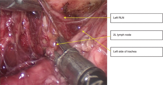
Upward the left RLN, station 2L can be dissected
Fig. 13.63 
Left RLN can be clearly exposed after dissection of 4L、2L lymph nodes


6.2 Abdominal Mediastinal Lymph Node Dissection
6.2.1 Technical Points
-
Cut off the hepatogastric ligament downwords the left lateral aspect of hepatoduodenal ligament and right gastric vascular arch. The pancreas head and branches of the coeliac axis in the lesser omentum can be revealed clearly. The assistant can gently depress the cranial part of the head of pancreas. This helps to show the splenic vessels well during the lymph node clearance (Fig. 13.64).
Fig. 13.64 
The pancreas head and branches of the coeliac axis in the lesser omentum being revealed
-
After left gastric artery is cut, dissection is continued cranially with ultrasound knife along with crura of diaphragm. This makes the para-cardia soft tissue including lymph nodes resected en bloc (Figs. 13.65, 13.66, 13.67, and 13.68).
Fig. 13.65 
The left gastric artery and nodes around the base of the left gastric vessels are revealed after cutting off the gastric coronary vein
Fig. 13.66 
Cutting off the left gastric vessels
Fig. 13.67 
Nodes around the base of the left gastric vessels are dissected
Fig. 13.68 
View after clearance of the para-cardia soft tissue including lymph nodes


6.2.2 Anatomical Landmarks
-
The left gastric artery: arises from the celiac artery and runs along the superior portion of the lesser curvature of the stomach. Gastric coronary vein runs along with it and more superfacial, which is a good anatomic landmark.
-
Pylorus part: connects the stomach to the duodenum, below which is the original of gastroepiploic arcade. It is the right edge when open the gastrocolic omentum.
6.2.3 Operating Procedure
-
1.
Cut off the hepatogastric ligament on the left lateral aspect of hepatoduodenal ligament and upward side of right gastric vascular arch. The gastric coronary vein can be revealed, and the left gastric artery is just located below. Nodes around the base of the left gastric vessels are dissected to delineate the left gastric artery and vein separately. The areolar tissue and nodes along the common hepatic artery are dissected and taken medially, along with the gastric nodes (Figs. 13.65 and 13.66).
-
2.
The assistant depress the cranial part of the head of pancreas gently to show the splenic vessels well. The nodes along the splenic artery are then taken (Fig. 13.69).
Fig. 13.69 
The nodes along the splenic artery are taken
-
3.
After left gastric artery is cut, dissection is continued cranially with Harmonic Ace along with crura of diaphragm. This makes the para-cardia soft tissue including lymph nodes resected en bloc (Figs. 13.67 and 13.68).
-
4.
The stomach tube can be fashioned intra-corporeally using staplers. Lymph nodes at the lesser curve can be resected at the same time. Lymph node dissection is finished.

Suggested Reading
Weijs TJ, Berkelmans GH, Nieuwenhuijzen GA, Ruurda JP, Hillegersberg RV, Soeters PB, Luyer MD. Routes for early enteral nutrition after esophagectomy. A systematic review. Clin Nutr. 2015;34(1):1–6.
Yu XB, Lin Q, Qin X, Ruan Z, Zheng J, Zhou JH, et al. Efficacy of early postoperative enteral nutrition in supporting patients after esophagectomy. Minerva Chir. 2014;69:37e46.
Fujita T, Daiko H, Nishimura M. Early enteral nutrition reduces the rate of lifethreatening complications after thoracic esophagectomy in patients with esophageal cancer. Eur Surg Res. 2012;48:79e84.
Rino Y, Yukawa N, Murakami H, Sato T, Takata K, Hayashi T, Oshima T, Wada N, Masuda M, Imada T. Primary placement technique of jejunostomy using the entristar™ skin-level gastrostomy tube in patients with esophageal cancer. BMC Gastroenterol. 2011;31(11):8.
Jenkinson AD, Lim J, Agrawal N, Menzies D. Laparoscopic feeding jejunostomy in esophagogastric cancer. Surg Endosc. 2007;21(2):299–302.
Chen B, Zhang B, Zhu C, Ye Z, Wang C, Ma D, Ye M, Kong M, Jin J, Lin J, Wu C, Wang Z, Ye J, Zhang J, Hu Q. Modified McKeown minimally invasive esophagectomy for esophageal cancer: a 5-year retrospective study of 142 patients in a single institution. PLoS One. 2013;8(12):e82428.
Guo W, Ma X, Yang S, Zhu X, Qin W, Xiang J, Lerut T, Li H. Combined thoracoscopic-laparoscopic esophagectomy versus open esophagectomy: a meta-analysis of outcomes. Surg Endosc. 2016;30(9):3873-81.
Luketich JD, Pennathur A, Franchetti Y, Catalano PJ, Swanson S, Sugarbaker DJ, De Hoyos A, Maddaus MA, Nguyen NT, Benson AB, Fernando HC. Minimally invasive esophagectomy: results of a prospective phase II multicenter trial-the eastern cooperative oncology group (E2202) study. Ann Surg. 2015;261(4):702–7.
Mu JW, Gao SG, Xue Q, Mao YS, Wang DL, Zhao J, Gao YS, Huang JF, He J. Updated experiences with minimally invasive McKeown esophagectomy for esophageal cancer. World J Gastroenterol. 2015;21(45):12873–81.
Sihag S, Kosinski AS, Gaissert HA, Wright CD, Schipper PH. Minimally invasive versus open esophagectomy for esophageal cancer: a comparison of early surgical outcomes from The Society of Thoracic Surgeons National Database. Ann Thorac Surg. 2015. doi:10.1016/j.athoracsur.2015.09.095.
Spector R, Zheng Y, Yeap BY, Wee JO, Lebenthal A, Swanson SJ, Marchosky DE, Enzinger PC, Mamon HJ, Lerut A, Odze R, Srivastava A, Agoston AT, Tippayawang M, Bueno R, Brigham Esophageal Study Team (BEST). The 3-Hole minimally invasive esophagectomy: a safe procedure following neoadjuvant chemotherapy and radiation. Semin Thorac Cardiovasc Surg. 2015;27(2):205–15.
Author information
Authors and Affiliations
Corresponding authors
Editor information
Editors and Affiliations
Rights and permissions
Copyright information
© 2017 Springer Science+Business Media Dordrecht
About this chapter
Cite this chapter
Prachand, V. et al. (2017). Thoracoscopic and Laparoscopic Esophagectomy with Cervical Anastomosis. In: Wang, J., K. Ferguson, M. (eds) Atlas of Minimally Invasive Surgery for Lung and Esophageal Cancer. Springer, Dordrecht. https://doi.org/10.1007/978-94-024-0835-5_13
Download citation
DOI: https://doi.org/10.1007/978-94-024-0835-5_13
Published:
Publisher Name: Springer, Dordrecht
Print ISBN: 978-94-024-0833-1
Online ISBN: 978-94-024-0835-5
eBook Packages: MedicineMedicine (R0)