
Abstract
In the HW/SW interface domain, specification of memory architecture and software-accessible hardware registers are both relevant for the implementation of hardware and the firmware running on it. Automated code generation of both HW and SW artifacts from a shared data source is a well-established method to ensure consistency. Metamodeling is a key technology to ease such code generation and to formalize the data structures target code is generated from. While this can be utilized for a wide range of automation and generation tasks, it is particularly useful for bridging the HW/SW design gap.
Metamodeling is the basis for the construction of large model-driven automation solutions that go far beyond simple code generation solutions. Based on the formalization metamodels provide, models can be incrementally transformed and combined to create more refined models for particular design tasks. IP-XACT and UML /SysML can be utilized within the scope of metamodeling . The utilization of these standards and the development of custom metamodels – targeted to specific design tasks – have proven to be highly successful and promise large potential for further productivity increase.
Access provided by CONRICYT-eBooks. Download reference work entry PDF
1 Introduction
Productivity increases in the design of embedded systems always built on the idea of predesigning modules from smaller components, providing an abstract model and other views and packaging all that together for use in a higher-level design environment.
First, semi-custom design prepacked transistors to logic gates and provided models with logic functions, propagation delay, and a graphical representation symbolizing the functionality of the gate. Typical representatives for prepacked gates are AND gates with two, three, or four inputs and one output or a D flip-flop with clock, reset, and data (normally called D) input and one output (normally called Q). This packing also enabled the use of gates in a schematic editor which provides a graphical view of the model. This stage of development permitted increasingly complex designs which could no longer be manually handled on the lower levels of abstraction. The final layouts were therefore done by fully automatic place and route tools.
Next, gates were prepacked to RT components, associated with register-transfer functionality and with untimed or clock-related timing. The packing was enriched with schematic views, with operators or program constructs and their mapping to the RT components. A good example for this is an adder which supports various sized inputs and the associated information that a “+”-operator can be mapped to it. The essential achievement of this abstraction is that RTL synthesis tools can map RTL descriptions to gate-level netlists in an automated way.
Further pursuing this approach, IP components were introduced that were pre-implemented in RTL and associated with more abstract TLM models to enable early and efficient simulations of multimillion – if not billion – transistor chips. Although that approach is now about 15 years old, this technique is not fully established. If established, generation of TLM and RTL top levels – i.e., abstract model and implementation – from a single source model is not a widely used approach. This is one of the main reasons for delayed introduction of automated IP-based design with TLM models: automation as provided by layout and RTL synthesis tools is not available. Further abstraction – except for some prepacked subsystems – is not widely used today [21].
Solely relying on the reuse of prepackaged items makes it very hard to implement innovative products since innovation is limited to novel combination of pre-implemented items. To address this limitation, RTL synthesis provided an additional abstraction: the ability to describe the behavior of a design using sequential constructs known from programming languages following a specific coding style. By applying a mapping – called inference in the RTL domain – these sequential constructs are mapped to RTL netlists and RTL primitive components that are then further optimized and synthesized as described above. For example, an if-statement causes the insertion of multiplexers for all signals assigned in the statement blocks.
The increase of productivity in RTL-synthesis provided for a wide range of digital designs through behavioral constructs could however not be repeated. High-Level Synthesis (HLS) tools, state machine synthesizers, or processor generation tools – to name only some – could improve productivity only in very limited fields of application. Moreover, reuse and composition of IP components do not give the productivity increase that is often claimed since they help to design chips with a lot of transistors, yet the transistors still need plenty of custom firmware and software on top of them to work properly.
If a single tool cannot provide system-level automation – i.e., automation beyond implementation level – for a wide range of applications, why not use a tool suite with tools that follow the same concept, interact, and together provide a wide range of automation [8]. This approach is exemplified by Office suites which provide a collection of tools for presentations, text documents, spreadsheets, project management, and much more.
However, simple scripting as successfully used by many designers (see, e.g., [27]) is too expensive to provide a sufficient number of tools at an acceptable cost and effort. Metamodeling techniques [7] provide a substantial measure to dramatically shorten the building time of such tools. Therefore metamodeling is one key technology to enable system-level automation via tool suites and to ease the interaction between tools which are part of these tool suites.
The goal of this book section is to introduce metamodeling in general and to show how it helps to increase productivity around the HW/SW interface. In the first subsection, we introduce the general concept of metamodeling and show early metamodeling technologies. Afterward, we give a formal definition of a metamodel illustrating the formalization and giving an idea, on how metamodels can be used in a formalized design process. Finally, we describe some metamodeling techniques in use, show the idea of automatic view generation around the HW/SW interface, and illustrate the basic structure of a metamodeling framework.
2 What Is Metamodeling About
First of all, metamodeling is different from other modeling approaches and also uses the term model differently than, e.g., in semi-custom or RTL design. This is further elaborated in Sect. 32.2.2. In metamodeling , a model describes an entity, mostly an intended design by its properties, its sub-entities, and the relationships between them.
2.1 A First Example
2.1.1 A Simplified View on the HW/SW Interface
Figure 32.1 shows a very simple metamodel of an IP’s register interface. Comparable register interfaces are a key component of generic HW/SW interfaces. The HW/SW interface works basically as follows:
-
By writing a value to the base address of the IP plus an internal offset, a value is passed from software to hardware. From the SW point of view, this is similar to writing to a memory cell. Therefore, SW can treat those addresses as special variables. Additionally hardware can be attached to the register, e.g., to trigger actions when the register is accessed or when a specific value is written. Connection of the registers to the IP-HW is done via wires. IP-HW then processes the values of those wires.
-
Storing a value in the bitfield from the hardware side or giving access to HW wires via the bitfield provides a way for the software to read a value from hardware. After having read the register the bitfield resides in, the software can further process the value. Similar to writing of values, SW handles the values read from the IP-HW like values from a memory. They can thus be treated like special variables in the software context.

Simple metamodel of register interfaces
In the following we focus on this basic mechanism, ignoring that there are additional possibilities for HW/SW interfaces such as CPU accessible special function registers, interrupts, or DMA request lines. When taking a closer look at the conceptual description above and considering the abstraction levels mentioned in the introduction, it becomes clear that several levels of abstraction with the same or different Model of Computation are bridged:
-
The software side follows primarily a sequential, control flow-oriented execution order. The software is mostly developed in C and C++ – although assembler code is still used. These descriptions do not contain timing information and individual threads of execution have no degree of parallelism.
-
The hardware side follows several concepts. Depending on the level of abstraction the hardware is observed from, it uses different modeling languages:
-
When observed from the gate-level perspective, connected timed primitives mostly described in Verilog are used.
-
On RTL, additional synchronous control flow or data flow is an appropriate view, typically modeled in VHDL or SystemVerilog.
-
TLM communicating processes are mostly coded in SystemC.
-
2.1.2 A First Metamodel
Instead of trying to make one model composed of sub-models, each following an own model of computation and being interlinked with a multi-domain formalism as proposed in [12], metamodels follow another idea: metamodels identify involved entities and define their attributes and relations. Further, metamodels also define constraints such as types, valid values, or valid multiplicity.
Figure 32.1 shows the definitions for the key entities involved in a HW/SW interface: Component, Register, and Bitfield. Component is the root node. In this model, it has a required string attribute Name and an unlimited number of registers. The latter is shown by the association arrow and the multiplicity *. Each Register has the mandatory attribute Offset, specifying the offset of the register in the address space of the component. Since a register must have this attribute, its multiplicity is set to 1. In addition, the offset must be a number which is defined by the type int of the attribute. Similarly, the register has a definition of its Size.
Finally, a register has one or more bitfields, again shown by the association arrow pointing at Bitfield and the multiplicity 1..*. A Bitfield has an offset Offset in the bit space of the register and a Size. Their type is int since both must be an integer number. Both have multiplicity 1 since they are mandatory attributes for a bitfield. To specify how a bitfield can be accessed, our register metamodel has four mandatory Boolean attributes SWreadable, HWreadable, SWwritable, and HWwritable.
Figure 32.1 also shows two Unified Modeling Language (UML) generalization arrows. These arrows point from the entities Register and Bitfield to Description. They indicate that the entities Register and Bitfield acquire all attributes and associations from the arrow target Description. Since Description has the mandatory string attribute Name and the optional string attribute Comment, Register and Bitfield have these attributes too. Of course, Register and Bitfield acquire all properties of these attributes as well. Thus, inheritance does not provide additional measures to describe entities; however, it simplifies and structures the description of their properties.
If you noticed that Fig. 32.1 resembles a UML class diagram, you are right: Fig. 32.1 was captured with DoUML, an open-source UML editor [24]. Although metamodels and UML class diagrams have many things in common, they are not the same. As we will see later, metamodels are used in UML to define class diagrams.
2.1.3 A First Model
With a metamodel at hand, a so-called model can be built that meets the constraints of the metamodel. In other words, legal instances of the metamodel can be built. The metamodeling technique follows the idea of separation of model and view, RTL models or SystemC-TLM models are thus called views in metamodeling terms. Before we discuss views in Sect. 32.2.1.4, we take a closer look at a model.
Figure 32.2 shows an example of a model specified in a graphical way using a UML object diagram. The model describes one instance of Component, its two registers R1 and R2 and its four bitfields B1 to B4. All Name attributes are set, i.e., the multiplicity constraints imposed from the metamodel are satisfied here. No Comment is set here which is legal since its multiplicity defined in the metamodel makes the attribute optional. All other mandatory attributes are set. The attributes Offset and Size are set to integer values, and HWr, HWw, SWr, and SWw are set to the Boolean values True or False.

Simple model of a register interface
There are further constraints originating from the semantics underlying the domain modeled here. These constraints are also met, which are easily comprehensible when looking at the diagrams. For example, every bitfield can either be read or written from each design domain, i.e., at least readable or the writable from software, as well as at least readable or writable from hardware. Further, the size of the bitfields is smaller than the size of the register. Since these additional constraints cannot be shown in a graphical way, they can be annotated in the tool capturing the metamodel either using a specific constraint language such as Object Constraint Language (OCL) (see [33]) or a programming language.
The model describes a component called Simple. This component has two 16-bit registers R0 and R1. R0 is at the relative address 0 and R1 at the relative address 1. In contrast to what one might assume, the register does not describe a storage element in our model. Instead, it only describes an addressable shell. Bitfields are responsible for holding data and therefore the access rights are specified here. In our case, if a bitfield cannot be written from the SW side, the value intended to be written via the register access is simply ignored. If it cannot be read, then the value 0 is returned. On the HW side, read and write access flags determine if there is a line from the register field to the HW core of the IP. The value written to HW is stored in a temporary register and the read value is directly taken from the IP core. These are all assumptions underlying our simplistic model. Industrial strength models such as IP-XACT (see Sect. 32.4.2.1) offer a wider range of possibilities here.
In addition to the UML diagram specification, models can be specified in many other ways, using, e.g., XML , JSON, or spreadsheets. It is important to assert that there is only one place where – and only one way how – the model is defined. This is called single source approach and prevents inconsistencies. It is especially important on the HW/SW interface since several design domains are bridged here.
2.1.4 First Views
2.1.4.1 Documentation
For this model, several views exist in the design process. One of them is documentation. A tabular representation of such a documentation view is shown in Table 32.1. This view is used, e.g., by the verification engineers validating the interface, the software and hardware engineers making the interface, and by the customer developing software for the product the IP is integrated in. This table and all views shown here are simplified to provide a better perspective on the overall methodology. For an industrial documentation, please take a look, e.g., at [17].
2.1.4.2 RTL Code
A possible RTL view of our model is shown in Fig. 32.3. The bus interface is assumed to consist only of Addr, DataIn, DataOut, En, and Wr. En is “1” if the IP is accessed and Wr is “1” if a register should be written. Bus and register are assumed to have the same clock and reset signal and there is no pipelining or other delay on the bus. Of course, component metamodels such as the aforementioned IP-XACT have possibilities to define more sophisticated buses (e.g., AXI, AHB, or APB) which then lead to more complex bus interfaces. However, they follow the same basic concept that is introduced here.

VHDL file
The first process SW_WRITE is responsible for write accesses from the SW side and the second process SW_READ for read accesses. The first process is also responsible for the inference of the synchronous memory elements needed for storing the bitfield values written by the software. The second process is responsible for the multiplexers needed to provide the right value to SW via the port DataOut. The bitfields which cannot be accessed from SW are simply omitted. Similarly, only those bitfields marked to be SW readable contribute to the value to be passed to SW. All bits of a register with no bitfield contribution are filled with 0 as shown in line 40.
If a bitfield is written and read from the same party – as the case for bitfield B1 of our example – then the IP-HW is responsible to feed either the same value back or a different one. It is worth noting that it is therefore not guaranteed that the same value which is written is read back.
For each bitfield that is read by the hardware, a port is created. Port R0_B1_o in line 12 illustrates the format of the names of these ports: They consist of the name of the register the bitfield is part of (R0), the bitfield’s name (B1), and a character indicating the direction (o). These elements are concatenated to the port name with underscores (_).
Correspondingly, ports are created for bitfields written by the hardware. Finally, for each bitfield’s port, a type is selected which both matches with its size and can be merged to a legal value of DataOut.
2.1.4.3 C -Header File
Figure 32.4 shows a possible firmware view of the HW/SW interface. For each register, a struct with elements representing the bitfields is created. The size of a bitfield is defined using the “:” operator followed by the size. The type is always uint16_t indicating a 16-bit wide unsigned integer. The keyword volatile indicates that the bitfields may be modified outside the software. The compiler thus cannot cache the values, e.g., in a CPU register or optimize the number of read accesses and must access the raw bitfield every time it is used by the software (i.e., generally the C-code).

C-header file
The registers are then combined to an overall register interface reg_t using another struct. Assuming an instance SimpleInst0 and a pointer called SimpleInst0Ptr (see Line 17), then bitfield b2 can be accessed by:
SimpleInst0Ptr− > r1.b2
However, different C compilers won’t accept this coding style since “:” is not generally supported. Further, unit16_t may not result in the intended result.
To address this, a style similar to Fig. 32.5 might be needed. Here, inline functions are used to access the bitfields. Line 8 shows how access to the bitfields is provided using a combination of shift, mask, and type cast.

Another C-header file
There may be even more styles and variants of C’s HW/SW interface view since bus_t and bool may not be supported. For example, macros could be used instead of inline functions. For an overview of different coding styles, see, e.g., Chap. 5 “Hardware/Software Interface” of [6]. The important aspect of the metamodeling approach is the guaranteed consistency of all these views which is ensured by code generation from the same specification source.
So far, we have only seen a model as instance of a metamodel and as an additional view to all the existing views. Before identifying the case for metamodeling in Sect. 32.2.4, let’s discuss the metamodeling terminology and take a look at the evolution of metamodeling over the last decades.
2.2 Terminology
2.2.1 Metamodel
So far, we simply accepted the term metamodel as something that constrains a model but we did not dig deeper into the prefix meta. As opposed to metaphysics, which is not a specific domain of physics but a branch of philosophy, metamodeling is a term from computer science.
The relationship between both terms is that meta stands for beyond. While metaphysics deals with questions about the fundamental nature of being [13], metamodeling deals with fundamental concept of a model. Therefore, a metamodel models the domain of a model. In other words, a metamodel is a model of a model.
This definition is in line with the things that were already said about metamodeling . Our simple metamodel example models the domain of the HW/SW interface. It is a guide – and also a constraint – for each specific model of the HW/SW interface of a component.
2.2.2 Metametamodel
There is however also a metamodeling domain. The models of this domain are metamodels. These models of the metamodeling domain in turn have their own metamodels describing them. In other words, each model of the metamodeling domain (a metamodel) is an instance of its own metamodel; the metamodel thus has a metamodel. When viewed from the modeling domain, each model m has a metamodel mm. As this metamodel mm also has a metamodel, the latter is the meta-metamodel mmm of m.
An example of a meta-metamodel is shown in Fig. 32.6. It describes that a metamodel has a root class which has other classes and attributes, both of them in any multiplicity. Therefore, a class references a container for a subclass, which potentially redefines the name and specifies the multiplicity. For simplicity, base classes are not shown here. This does not reduce the expressiveness of the meta-metamodel since they do not contribute to the modeling possibilities as such.

Meta-metamodel
Interestingly, this meta-metamodel can be defined using the formalism that is also used for the metamodel. This concept is not unusual in computer science. For example, the BNF grammar can be defined using an BNF grammar itself (see [34]). This is a hint that there might not be a meta-meta-metamodel, although there is some research to find this even more basic model.
Figure 32.7 shows the component metamodel from Fig. 32.1 as an instance of the meta-metamodel shown in Fig. 32.7. The object ComponentMM is the root node in the meta-metamodel instance named ComponentMM. Its only associated object Register of type Class is the root node of the metamodel. Its associated objects Offset, Size, and Name of type Attribute specify the attributes of Register. The object Register also has an associated Subclass object defining that the associated object Bitfield of type Class. The multiplicity 1..* of this association is represented by MaxOccurs=1 and MinOccurs=-1. The Bitfield class has seven attribute objects associated with, three of which are not completely shown.

Meta-metamodel instance: component
2.2.3 Metamodeling Layers
The relationships of the introduced artifacts, views, models, metamodels, and meta-metamodels, are pictured in Fig. 32.8. Here, we see that the artifacts are labeled from M0 to M3, a terminology introduced by OMG (see [22]). We also see that the higher numbered artifacts define the structure of their directly lower numbered artifact. In turn, the lower labeled artifacts are an instance of – or in other words comply to – their directly higher numbered artifact. The M0-M1 relation differs as it is a content wise and not a structural dependency. In some cases, this dependency may also be structural, as the introduction of model-to-model transformations in Sect. 32.4.2.3 shows.

View, model, metamodel, and meta-metamodel
Although the depicted designation of layers is widely accepted, there are two alternative approaches. A small set of publications follow the idea that HW design deals with models, i.e., what we call a view is in their definition a model. Consequently, what we refer to as models, metamodel, and meta-metamodels becomes metamodel, meta-metamodel, and meta-meta-metamodel. This definition however is not that useful in the HW/SW interface domain, since neither documentation nor the C-code are models.
Another definition of layers is used in the Eclipse Modeling-Framework (EMF) world (see Sect. 32.4.1.4). Here, the running program embedded in the Eclipse framework is seen as world, i.e., being level M0. Unfortunately the data of the program is nothing else than our model. Since they are part of the “world,” a model in the Eclipse terminology defines the structure of the data, which is – in our terminology – a metamodel. Consequently, the terminology is shifted one level down and only has view, model, and metamodel.
For the rest of the book chapter, we will follow the widely used OMG definition as depicted in Fig. 32.8.
2.3 History and Known Technologies
Metamodeling is not as new as it sounds. The basic idea was introduced about 40 years ago by Chen. In those days, it was called entity-relationship model (see [3]). Most of the metamodeling concepts introduced above were either already there or introduced some years later by Smith and Smith (see [29]). From there on, they were continuously improved, especially in the domain of databases. It is therefore no surprise that there is still a relationship between database schemas and metamodels. Entity relationship diagrams were also used in the definition phase of the Jessi Common Framework Initiative (see e.g., [35]), now used to define entities in the hardware domain. First, mainly structurally oriented entities were modeled. The definition of the EDIF Information Model by Kahn (see [18]) used the entity-relationship methodology also named information model here. Due to complexity, it was expressed in a textual form using the EXPRESS notation (see [26]). The entity-relationship notation was however not limited to structural things. Soon later Kahn and Guimale defined an information model for VHDL that covered behavior and time as well [14]. A summary of all the work around entity-relationship models of hardware was collected in [2]. Here, the term metamodeling was already used in conjunction with hardware modeling.
Unfortunately, research activities around metamodeling in the hardware domain cooled down for a while. The Open Access Database (see [15]), intended to store hardware design data, was, for example, associated with an API , however not with an unambiguous metamodel. Fortunately, metamodeling grew further in the software world under the umbrella of the OMG . The design of XML , UML, and other technologies was based on metamodels.
2.4 The Case for Metamodeling
After having seen that metamodeling is not that new a concept in hardware design, this section now discusses the benefits of metamodeling in the design process. We ended Sect. 32.2.1.2 with the statement that so far, metamodeling is just an additional view in the design of the HW/SW interface. The following carves out the benefits of metamodeling , making it a very useful technology in the TLM area and HW/SW interface automation area.
The first benefit is that the views illustrated in this chapter’s examples – and many more – can be generated from a model. Therefore, generators have to be built that translate the content of the model to the syntax of the target view. So, all but one view – the model – can be completely derived from the model and no longer need to be developed manually.
The second benefit is that the content of the model must not necessarily be entered manually. Often, parts of the model are already defined in a specification. By providing a specification reader – or a single source for specification and model – additional time can be saved and consistency between specification and design views can be improved, if not guaranteed.
The third benefit is that big parts – especially the APIs – of the software needed to read the specification and to write the views can be automatically generated from a metamodel. Going hand in hand with that step, a good documentation via the metamodel diagram and a consistent way of treating models is achieved. This is nothing else than the application of modeling and generation techniques to the construction of the automation tools.
All this is summarized in Fig. 32.9. Since not stated explicitly yet, a further detail worth noting, the APIs needed to handle different metamodels can be also generated from the meta-metamodel.

Concept of a metamodeling framework
In order to build such a framework in a safe way, a good formal basis is needed. Diagrams, as shown so far, give a good overview but are less suited to define all details. In the next part of this chapter, we therefore introduce the formal definition of models and metamodels.
3 A Formal Model of Metamodeling
This section provides a formalization of metamodels, their models and the relation between metamodel and model. The representation used in the following is based on a set-oriented perspective on models. This approach was selected as it permits an intuitive description of the constraints metamodels impose on their models.
3.1 Basic Definitions
Models consist of correlated objects which contain attributes. Both the correlations and the attributes are named. Moreover, the attributes are multisets that contain some values. The following definitions provide a formal definition of these names and of the values that can be stored in model attributes.
3.1.1 Legal Names N of Correlations and Attributes
All legal names in a model are grouped in the set N. In this formal model, we define this set as a set of words over an alphabet Σ. The characters selected for this alphabet can be picked from an arbitrary set. It is convenient to rely on a set of words that can be easily mapped to potential view languages (i.e., words that are legal identifiers in common programming and modeling languages). Equation 32.1 defines such a set N of valid names:
where \(\mathscr{L}(e)\) describes the set of the regular language defined by the regular expression e.
3.1.2 Legal Values for Attributes
Attributes in models are typed. These types define the possible values an attribute can take and their interpretation. In this formal representation, type T 0 is defined by a set. This set contains all the values this type allows. An attribute of type T 0 can only take values v ∈ T 0.
In this formal model, some predefined types are provided. Each element in T = {I, B, F, S} defines such a type. Each type T 0 ∈ T is a set, containing all the values an attribute of the type T 0 may take.
The predefined sets have the following content:
-
\(S:=\varSigma ^{{\ast}}:=\{ w_{0}\ldots w_{n}\vert n \in \mathbb{N}\}\cup \{\epsilon \}\) is the set defining the language of all valid strings. ε is the empty word and Σ is the alphabet of all possible characters.
-
I is the set of all words representing valid integers.
-
F is the set of all words representing valid floating point numbers.
-
B: = {True, False} are the truth values of propositional logic.
The string type S occupies a special position here: It is a superset of any other type. Consequently, it contains any value an attribute – regardless of its type – may take:
Each of sets introduced above has an infinite number of elements. Metamodeling environments have predefined types such as integers of limited sizes and floating point numbers of various precision, originating from the runtimes used or the programming languages they are implemented in. They therefore provide subsets, constraining the range of integers, the precision of floating point numbers, and the length of elements in S which makes all type sets finite.
To work with attribute values, the metamodeling environment has to be able to interpret the elements in the type sets. For example, integers are used in the metamodel to define the minimum and maximum multiplicities of elements in the model. To enforce these definitions and to work with the information they provide, the metamodeling environment has to understand the integer type: It has to provide a bijective mapping \( \mathrm {I} \text{nt}: \,I \rightarrow \mathbb{Z} \cup \{\infty \}\). Using this and other mappings, a runtime environment can define operators such as addition and multiplication on integer or floating point numbers.
3.2 A Formal Representation of a Model
3.2.1 The Set of All Models
This formal representation of models puts emphasis on the fact that everything is a model. Section 32.2.2 illustrates that what is a model exclusively depends on the point of view on the modeled system. Any model A becomes a metamodel not by definition but because it is instance of a model we perceive as meta-metamodel. Likewise, a model A can become a metamodel if there is a model C that is an instance of A.
The set of all models M therefore contains models, metamodels, and the meta-metamodel. Every model m ∈ M that is part of this set has the same structure which is defined in the following.
3.2.2 Definition of a Model
Each model m ∈ M is a tuple
where n ∈ N is the name of the model (an element from the set of all identifiers). mm ∈ M is the metamodel which m is instance of. The main part of the model is the set of objects O. It contains the actual elements of a model.
3.2.3 The Set of All Objects O of a Model
Each object o ∈ O is a tuple:
where
-
c is the class definition of the object. This definition is an object of the metamodel the model adheres to:
$$\displaystyle{ \forall m \in M,\ \forall o \in m.O: o.c \in m.\mathit{mm}.O }$$(32.5) -
i ∈ I is the name or unique identifier of the object. As the name suggests, there are never two objects in a model which have the same identifier:
$$\displaystyle{ \forall o_{i},o_{j} \in m.O: o_{i}.i = o_{j}.i \Leftrightarrow o_{i} = o_{j} }$$(32.6) -
A is a set of object specific attributes where each attribute a ∈ A is a tuple of name and assigned values:
$$ a = (n \in \ N,E),\quad E \subseteq S $$(32.7)n is the name of the attribute and E is a multiset containing the attribute’s values. If an attribute contains several identical values, the multiset E contains the value several times. For each attribute, there is only one tuple in an object’s o. A set. Equation 32.8 shows that if an attribute contains multiple values, these values are all in the multiset of the same attribute tuple.
$$\displaystyle{ \forall a_{i},a_{j} \in o.A: a_{i}.n = a_{j}.n \Rightarrow a_{i} = a_{j} }$$(32.8)
The following will look at the elements K and R of the object tuple o. Analogous to the set of attributes A, both K and R are of a set of tuples (n ∈ N, E), where n is a name and E is a set of values:
-
K describes the children of the object o. Each element k ∈ K is a tuple
$$ k = (n \in \ N,E),\quad E \subseteq I $$(32.9) -
R is the set of referenced objects. R describes referenced elements, a concept we did not yet introduce. They are still included here as they are an essential part of all modern metamodeling frameworks. References allow elements inside models to refer to other elements at object granularity. They can be compared to attributes containing a pointer to other objects instead of an attribute value. Each element r k ∈ R is a tuple
$$ r = (n \in \ N,E),\quad E \subseteq I $$(32.10)
Despite their largely similar structure, elements E which are part of tuples belonging to K and R have a different interpretation than elements belonging to tuples in A. The elements in E of an attribute contain actual values. In contrast, the elements E in a reference tuple r or child tuple k contain unique identifiers of other objects in the same model.
Example 1
The formal representation can now be used to describe any models as an element m ∈ M. Figure 32.10 provides an example for such a description. The model depicted here is the same model we used for our introductory example in Fig. 32.2.

An example of a model in its formalized representation
Further Constraints
Aside from the straightforward constraints already mentioned in the definition of the object tuple o, there are several further constraints:
-
For every element e ∈ E, there is an object in the same model which has an identifier defined by the reference target t:
$$\displaystyle{ \forall m \in M,\ o_{i} \in m.O,\ r \in o_{i}.R,e \in r.E:\exists o_{j} \in m.O: o_{j}.i = e }$$(32.11)Because of Eq. 32.6, there is exactly one element for every identifier and the reference is unique.
-
Every object can be child of at most one element. In other words, every object has at most one parent. If we pick any two different objects o i and o j of the same model (therefore part of the same set m. O) and compare the intersection of their sets of children o i . K and o j . K, we will find that it is the empty set. Equation 32.12 illustrates that this is true if and only if we look at two different objects o i and o j .
$$\displaystyle{ \forall o_{i},o_{j} \in m.O\ \forall k_{i} \in o_{i}.K,k_{j} \in o_{j}.K: k_{i}.E \cap k_{j}.E\neq \phi \Leftrightarrow o_{i} = o_{j} }$$(32.12) -
Every object is child of exactly one other object except for one object which is said to be the model’s root. Equation 32.13 shows that there is exactly one object for which no other object exists that contains the object in its set of children (\(\exists !\) is the uniqueness quantification operator stating that there is one and only one)
$$\displaystyle{ \exists !o_{i} \in m.O\ \nexists o_{j} \in m.O,\ k \in o_{j}.K: o_{i}.i \in k.E }$$(32.13) -
The child relationship defines a hierarchy. For any two objects o i , o j ∈ O where o i is direct or indirect child of o j , o j must not be direct or indirect child of o i . For any sequence of objects where each object is child of its predecessing object, the first object and the last object must not be equal:
$$\displaystyle{ \begin{array}{llll} \forall (o_{0},\ldots,o_{n}) \in O^{n+1}\ \forall i \in [0,n - 1]:\exists k \in o_{i}.K:\ &o_{i+1}.i \in k.E\\ & \Rightarrow o_{ 0}\neq o_{n}\\ \end{array} }$$(32.14) -
The constraint from Eq. 32.8 also applies to o. K and o. R.
In addition to that, the names n are not only unique within the attributes, children, and references of one object but also across the whole object. If an object has an attribute with the name n 0, there must not be any reference or child which has the same name. In other words, children, attributes, and references share the same namespace. The pairwise intersection of all child names, all attribute names, and all reference names must therefore be empty:
$$\displaystyle{ \forall o \in O\ \forall a,b \in o.K \cup o.A \cup o.R:\ a.n = b.n \Leftrightarrow a = b }$$(32.15)
Sets of All Models, Metamodels, and Meta-Metamodels
This formal model defines three layers of models as illustrated in Fig. 32.8 of Sect. 32.2.2. These three layers are formalized here as three sets M, MM, and MMM. The largest of these sets is the set of all models M which was already introduced in the beginning of Sect. 32.3.2.
A metamodel mm ∈ MM is a model that describes the structure of a model. A model m a ∈ M becomes a metamodel through the existence of a model m b ∈ M which is an instance of it. Metamodels are therefore also models and the set of metamodels is given by
A model becomes a meta-metamodel through the existence of a metamodel which is instance of it. The set of meta-metamodels is therefore given by
It is obvious that MM ⊂ M and MMM ⊂ M. As any meta-metamodel necessarily has an instance, it is also a metamodel and the two equations simplify to MMM ⊂ MM ⊂ M:
Based on this definition and the assumption that there is only one meta-metamodel, it is trivial that the meta-metamodel is its own metamodel:
The meta-metamodel can therefore be used to describe itself. Equivalent notations for this are mmm. = mmm or mmm = (n, mmm, O)
3.3 Metamodel Constraints on Models
In a bottom-up approach, the formal definition of models in formal models presented section 32.3.2.2 already lists some constraints on models that originate from the meta-metamodel we agreed on.
In the following, we complement this with other constraints a metamodel mm imposes on its models m. Approaching the problem top-down, we first declare names for attributes and objects of the meta-metamodel: n name , n ref , n comp , n attr , n min , n max , n type ∈ N. Next, a formal description of the meta-metamodel mmm as instance of itself is developed. Finally, a list of constraints is provided.
Meta-Metamodel
Any metamodel can then be uniquely represented as instance of this meta-metamodel mmm:
Metamodels instantiate these uniquely named objects and provide values for their attributes. What we described above is in fact both the description of the meta-metamodel mmm and a metamodel mm (as it is instance of mmm).
We can now use the description of the meta-metamodel and provide formulae for how metamodel objects constrain their models. These descriptions are simplified by a set of helper functions.
Helper Functions
The functions O A, mm , O K, mm , and O R, mm are defined for any model m. They map any object of the model to the set of metamodel objects that describe its attributes (O A, mm ), children (O K, mm ), and references (O R, mm ) or a combination thereof (O KR, mm , O KRA, mm ). In programming, such a mapping is called introspection. Each of them therefore maps from the pre-image set m. O of any model to the image set \(\mathscr{P}(m.mm.O)\):
The function \(\mathscr{P}(X):=\{ U\mid U \subseteq X\}\) maps any set X to its powerset.
Moreover, the function E name returns the set of all values of an attribute provided the attribute name. The function o byid returns an object given by its unique identifiers:
Constraints
The following constraints are valid for any model m of metamodel mm:
-
For each attribute, composition, and reference, the metamodel restricts the minimum and maximum number of elements that are contained or referenced. This number is commonly referred to as multiplicity:
$$ \begin{array}{rrrrr} \forall y \in o.A \cup o.K \cup o.R,\ o_{mm} \in O_{KRA,mm}(o),\ e_{max} \in E_{name}(o_{mm},n_{max}): \\ y.n \in E_{name}(o_{mm},n_{name}) \Rightarrow \textsc{Int}(e_{max}) \geq \vert y.E\vert \\ Y \in \{ K,R,A\}\ \forall o_{mm} \in O_{Y,mm}(o),\ e_{min} \in E_{name}(o_{mm},n_{min})\ \exists y \in o.Y: \\ y.n \in E_{name}(o_{mm},n_{name}) \wedge {\text{Int}} (e_{min}) \leq \vert y.E\vert \end{array}$$(32.25) -
For each attribute, the metamodel constrains the values that it can take. To do this, the metamodel object defining the attribute has a type property listing all possible values:
$$\displaystyle\begin{array}{rcl} \begin{array}{rclrcl} \forall a \in o.A,\ o_{mm} \in O_{A,mm}(o):&&\ a.n \in E_{name}(o_{mm},n_{name}) \\ && \Rightarrow a.E \subseteq E_{name}(o_{mm},n_{type})\end{array} \end{array}$$(32.26) -
Compositions and target references are statically typed through the metamodel. For each composition element and each reference, the metamodel constrains the metamodel object the that the target is instance of:
$$\displaystyle\begin{array}{rcl} \begin{array}{llll} \forall m \in M,\ y \in m.o.K \cup m.o.R,\ i_{target} \in y.E,\ o_{mm} \in O_{KR,mm}(o): \\ y.n \in E_{name}(o_{mm},n_{name}) \Rightarrow o_{byid}(m,i_{target}).c.i \in E_{name}(o_{mm},n_{type})\\ \end{array} \end{array}$$(32.27)
4 Metamodeling for HW/SW Codesign
4.1 Metamodeling Frameworks
The formal models presented in Sect. 32.3 lay the foundation for the correct design and construction of metamodeling frameworks. A first framework has already been sketched in Sect. 32.2.4. This section first discusses Model-Driven Architecture (MDA) and its impact on metamodeling frameworks. It then describes the metamodeling frameworks most widely used for automated design creation: XML , UML, and EMF. Next, standardized metamodels covering the HW/SW interface are introduced and the use of custom metamodels is motivated. Practical experience gained from the use of metamodeling in industrial applications finishes this section.
4.1.1 MDA
MDA – acronym for Model-Driven Architecture – is a vision of the Object Management Group (OMG ) (see [23] and [32]) for automation of code development via metamodeling , model-to-model transformations , and code generation. In the simple approaches toward metamodeling sketched in Fig. 32.9, a specification is first read into a model via a reader and then translated to the view via a generator . To implement the full MDA vision, this simple approach is extended: The target view is not generated directly from the first model, which is still close to the specification. Instead, the view is generated from a model that is closer to the target view’s structure and semantics. Since these two models may still differ too much, one or even more intermediate models might be introduced to further partition the translation. Figure 32.11 shows such a process with one additional intermediate model.

An advanced metamodeling framework
To structure this approach and to find criteria for the definition of the models involved, MDA introduces three levels of models:
- PSM::
-
A Platform Specific Model is very close to the target view. Model and view therefore have similar structure but different syntax. In addition, the Platform Specific Model has sufficient information about the environment of the final view.
A good example for a PSM is the Abstract Syntax Tree (AST) of the view’s underlying language which already includes references to libraries that are used in the programming or modeling environment of the platform. For the example of the hardware register view, the PSM would be the AST of VHDL with links to VHDL’s synthesis packages and libraries of reusable components.
If view generation starts from a PSM , the view can also be seen as an instance of the model and not just the content of the model since the view follows the structure of the model.
- PIM::
-
A Platform Independent Model does not include platform details but already depends on the targeted implementation’s semantics – or in SW terminology: It depends on the kind of computation being targeted.
A good example is a view’s language independent structural model being able to handle components, their instantiations and connections between them. However, such a model does not consider language specifics as VHDL’s component-based instantiation, its port signals types (e.g., std_logic) and out semantics, or Verilog’s wire-based style.
- CIM::
-
A Computation Independent Model focuses on items in the modeled domain, independent of their implementation. A very good example is the register model of our simple component, since it is independent of the target semantics (i.e., of a sequential programming language describing the SW access, of a TLM register model interfaced by a method, or of an event-driven VHDL model describing the HW part). This independence is precisely what is important for metamodels describing interfaces between domains. It is also easier to parse specification data into that model since a specification focuses on what the design should do and not on how the design shall be implemented.
In MDA, for each of the CIMs, PIMs, and PSMs, a metamodel is defined. This metamodel acts as the starting point and interface agreement for automation.
A metamodeling framework following the ideas of MDA is shown in Fig. 32.11. Here, the models are encapsulated in APIs with separate interfaces for writing and reading data (setAPI and getAPI). Using these interfaces, the data can be dumped into an intermediate storage based on the XML format, edited with a GUI or validated by check functions. These checks are derived from constraints provided by the metamodel or the meta-metamodel in use. All these components of metamodeling framework can be automatically generated using the metamodel description. Additional checks can be generated from OCL constraints associated with the metamodel or parts of it.
There are even several methods to automate the construction of translators. The view generator , for example, can either be derived from a metasyntax notation like EBNF or can be based on a template engine. The reader can, for example, make use of libraries or parser generators . All together, a metamodeling framework is a powerful tool that not only automates generation of views but also the construction of parts of the automation solution.
The metamodeling approach described in [8] and entitled meta-synthesis goes one step further. It also automates the building of automation tools by supporting merge and split of data during model-to-model transformation , dump and reload utilities for models, checks of model consistency, and execution control. Providing such a high level of automation makes it comprehensible how the use of models which are instances of metamodels helps to dramatically improve design productivity and design quality although the metamodels have to be built upfront.
In the following, we introduce the three metamodeling frameworks. EMF, synonym for Eclipse Modeling Framework , as well as XML and UML which describe both modeling languages and a modeling framework.
4.1.2 XML
XML , acronym for eXtensible Markup Language, is a markup language that is used to store and annotate data. There are many books on XML and lots of web pages detailing the usage of the language in different fields of application. Instead of providing an overview over this vast area, this book focuses on the special features of XML that can be used in the context of metamodeling .
One of XML ’s initial goals was to separate content and view, an idea that also underlies the metamodeling concept. The mix of formatting and data – as, e.g., used in older versions of HTML – should be overcome to ease information retrieval and to support different publishing styles. The resulting XML standards were therefore shaped in a way that allowed storing data which could also be used to capture models of metamodeling environments. Figure 32.12 provides an example of our simple component model encoded in XML .

The simple component model in XML format
Of course, a representation similar to Fig. 32.12 can also be used to store metamodels. UML, for example, defines the XML Metadata Interchange (XMI ) format as an XML -compatible markup language for storing models and metamodels. This XML Metadata Interchange (XMI) format is also used in the Eclipse EMF domain.
In addition, XML has a mechanism called XML Schema Definition (XSD ) to define the valid structure of an XML document, effectively defining a metamodel for XML documents. XSD has a set of powerful features for specification of valid values. Similar to the formal definition in 32.3, XML and XSD only deal with strings. All values in the pictured XML file are therefore embedded in double quotes. An XSD schema specifies the valid strings an attribute may be assigned with and how those then have to be interpreted, e.g., as a number or a Boolean value. Figure 32.13 shows the XML schema defining the validity of the XML file in Fig. 32.12. It carries the same information as the metamodel that was introduced in the introductory example in Fig. 32.1. It is, however, not as intuitive as the graphical view of the metamodel. In addition, the requirements on well-formed XML documents make the format a bit verbose. XSD documents are formatted in valid XML themselves. This allows existing XML parsers to read the schemas; however, it is also responsible for XSD ’s verbosity.

Component metamodel in XSD format
Specific to the XML -based MDA process is that the model is stored in a file and not in an encapsulated data model that is part of a program. This is shown in Fig. 32.14 on the same MDA flow as pictured in Fig. 32.11. Here, the transformations are done by XML processors which read XSLT, a transformation language for XML .

MDA using XML
XSLT can also be used to translate XML to any kind of textual view such as C-code or VHDL models. The only thing needed to build an XML CIM in the depicted XML MDA flow is therefore a reader. If the specification is available as an XML document, this reader might be an XSLT-based translation as well.
4.1.3 UML
UML is a widely used standard in the software world incorporating many concepts and notations that have proven to be successful. UML also defines an aligned graphical view on all the concepts included. The widespread adoption of UML brought a significant benefit compared to the situation before where different methodologies used different graphical notations for the same concepts or even the same notation for different concepts. UML as a whole however has a disadvantage: It is quite complex and some definitions are ambiguous.
All the notations – also called diagrams – are defined via a metamodel which in turn is defined on basis of a meta-metamodel. This UML meta-metamodel is called MOF (see [22]) – acronym for Meta Object Facility. Inside the MOF and essential MOF called EMOF and a complete MOF called CMOF is defined. Based on MOF, UML defines a standard intermediate called XMI which we already mentioned.
UML influenced metamodeling in many ways. Since UML diagrams also support behavioral notations like state or activity diagrams, it proves that metamodels are not restricted to structural information. Instead, a structure can be defined which has inherent execution semantics.
UML also supports class diagrams, which – or more precisely an extended subset of which – can be used to define metamodels in a graphical way. UML’s EMOF is thus conceptually very close to a class diagram. This is obvious since a class diagram structures data and a metamodel structures its domain in entities (classes), their properties (their attributes), and their relation to other entities (different kinds of associations).
Last but not least, UML has a built-in extension mechanism, which permits the adaption of UML to different needs and domains. The adaptability to different needs in particular is a noteworthy benefit of a modeling-based approach over the tool-based approach in system-level automation.
Stereotypes can be used to create new model elements, represented by \(\ll \ldots \gg\)-brackets. These model elements may also have their own graphical representation. In addition, stereotypes can be used to create completely new diagrams including their graphical representation.
The second mechanism is tagged values. They used to define additional properties for existing modeling elements or stereotypes. They include additional information needed for specific use cases. This information can also influence further processing of the model. When our simple component metamodel is used for HW generation, it can be extended with tagged values describing how many flip-flop instances should be generated for every bitfield:
-
Zero: Only wires would be generated in both directions.
-
One: Only one flip-flop group written by SW (as depicted in Fig. 32.3)
-
One shared: Flip-flops writable by HW and SW
-
Two: One flip-flop group being written by SW and read by HW as well as one flip-flop group being written by HW and read by SW
Other tagged values might specify if SW read and write accesses trigger pulses and edges at additional signals passed to the HW core.
It is important to note that tagged values modify the metamodel in an upward compatible way since they only add items. In contrast, UML’s third adoption mechanism called constraints adds new rules or modifies existing ones. Constraints can be used to remove an attribute from a modeling element. Code generators that rely on a removed field would fail.
A set of any of the defined extensions can be packed and provided as a so-called profile. SysML (see Sect. 32.4.2.2) is one example of such a profile. These profiles are called lightweight extensions since they don’t change UML’s metamodel. In contrast, a heavyweight extension would add new items, concepts, and relationships to UML’s MOF.
4.1.4 Eclipse Modeling Framework
EMF, synonym for Eclipse Modeling Framework, is a full-featured metamodeling framework. EMF uses Java as implementation and glue language and generates a Java API as well as other things for the specified metamodel (e.g., an editor model). EMF is fully integrated in the Eclipse framework. EMF is a good starting point for metamodeling since it is open source and can easily be obtained from the Eclipse Foundation. EMF’s web page (see [9]) refers to many online tutorials, webcasts, and video-casts. For those preferring old-style printed books, the key contributors to EMF collected an overview on EMF in [30]. There are also many forums around EMF helping with questions.
Diving into EMF is however not straightforward and it takes a while to get started with the framework. Many consulting companies around EMF offer their help. If someone prefers closed-source tools that come bundled with professional service, then he/she might look at the tools from MetaCase [20]. An important contribution of EMF to the metamodeling world is its meta-metamodel called ECORE . ECORE was designed to be able to map XML schema, UML metamodels (diagram types in UML terminology), and database schemas to one model. The ECORE model shown in Fig. 32.15 is conceptually identical to our first meta-metamodel shown in Fig. 32.6.

EMF ECORE meta-metamodel [10]
Figure 32.15 shows four additional modeling features: First, as already included in our formal model, ECORE has a reference mechanism implemented via EReference. This mechanism has similarities with association in EMOF. Via containment, references and compositions (the only hierarchical element in our simple metamodel) can be distinguished. Second, ECORE supports inheritance via eSuperTypes and eAllSuperTypes. Third, ECORE supports namespaces via EPackage. Fourth and last, ECORE supports enumerations via the EEnum and EEnumLiteral meta-classes.
Further, ECORE makes more use of inheritance. For example, all the naming is defined in the virtual classes EClassifier, ENamedElement, and EModelElement. Similarly, bounds and other features are derived from EStructrualFeature and ETypedElement.
The meta-class EFactory does not describe a modeling feature but methods to create the instances and to do string conversion. Finally, EAnnotation provides a measure to add data to the model that can be used, e.g., for view generation or model transformation.
Less obvious, yet just as important is that the API does not only permit access to the model. Instead, it also permits access to the metamodel items which are associated with the model items. In this way, introspection is supported for all model elements and meta-programming techniques can be applied. This allows different attributes to be handled by the same piece of code although they are differently typed. This facilitates the implementation of translators and view generators that support on any instance of one kind of meta-metamodel.
4.2 Related Standards
Around the XML metamodeling technology, two standards have been defined that are widely used in the HW/SW area: IP-XACT and SysML . This section gives an overview over the standards and afterward motivates the benefit of an application specific metamodeling approach.
4.2.1 IP-XACT
IP-XACT (see [19]) is a standard supporting automation of IP Integration and thereby automation of System-on-Chip (SoC) construction. A PDF version of the standard is available from the IEEE [16]. IP-XACT has wide professional support. Several Electronic Design Automation (EDA) tools support IP-XACT and almost all IPs have an associated IP-XACT view. There are also open-source tools supporting IP-XACT , e.g., Kactus2 (see [31]).
IP-XACT defines an XML Schema with additional semantic documentation of the schema items. From the modeling standpoint, IP-XACT primarily supports the definition of the following items:
-
Signals, interfaces, and bus structures as elements for the connection of components.
-
RTL, TLM, or mixed RTL and TLM connections.
-
Components describing hardware blocks of the IP. To interface with the HW world components offer interfaces for complex signal bundles and simple ports. Further, they can have parameters. Finally, components include the definition of the register layout and thus define most parts of the IP’s SW interface.
-
Definition of connection of IPs in a so-called System Model.
From HW/SW perspective, only a subset of the features IP-XACT provides are of interest.
The System Model, since it defines the involved components, the number how often they are instantiated and the instance names. The definition of the base address for each instance and derived from that the based addresses of the register fields is an important key for efficient software development.
The way how registers are specified is more advanced than in our simple model. Components have addressable units specifying their own base address inside the address space of the component and their own address range. Furthermore, the addressable units can be connected to interfaces. Like this, registers can be addressed via two or more CPU buses or over other protocols such as Serial Peripheral Interface (SPI). Figure 32.16 illustrates that the registers in IP-XACT and our register model share a similar underlying concept: Components have registers and registers have bitfields.

IP-XACT code fragment of registers
But IP-XACT also has some nice additional capabilities. For example, read and write access can be specified for address fields, registers, and bitfields. Further, the access is not defined via read and write flags but via access-field that can take the values read-only, write-only, as well as read-write. Also, writeOnce and read-writeOnce are supported.
In addition, IP-XACT allows to specify legal values for the bitfields. Each of the value items has a name, a value, and a description. In software, they can be mapped to enumeration types or macros making the SW access more readable.
Further, accesses can be byte accesses and bridge different types of endianness. Therefore ipxact:endianness and ipxact:addressUnitBits are associated with buses and address fields but not to singe registers.
Another important thing is the possibility to define the display name of registers and bitfields in addition to name and description. This display name may be used in the firmware headers since it can be easier to map it to target SW languages.
There is also a possibility to specify dimensions for registers, which allow – together with address fields – the hierarchical specification of the software-side register interface in a more structured way based on struct- and array-constructs.
However, IP-XACT focuses on IP integration and therefore describes only the SW side of the component. The hardware side is only covered by the attribute volatile. This attribute tells if the hardware may change the value written by the software. The way how and where the value is stored and how the HW access is done cannot be specified in IP-XACT .
4.2.2 UML∕SysML
This section focuses on SysML , an extended subset of UML, and describes where SysML modifies, adds, and skips UML diagrams or their features. Although both UML and SysML only speak of diagrams, these diagrams implicitly rely on an underlying metamodel, which all valid diagrams have to adhere to. This metamodel also provides semantics for the diagrams. There are many commercial and open-source SysML and UML tools available. In the Eclipse domain, the plugin Papyrus is widely used (see [11]).
UML and SysML diagrams can be subdivided into structural and behavioral diagrams. To describe behavior, UML and SysML introduce the notion of actions as basic items for functionality. SysML ’s behavior diagrams are:
-
Activity Diagrams: These diagrams are a bit different in SysML and UML. They consist of activities that specify transformations of inputs to outputs and actions responsible for the transformation. Activities produce and consume artifacts that might be passed via flow ports. Based on an underlying semantic of colored Petri nets, activities may have control and data flow inputs and outputs. Both can trigger the execution of activities. Activity diagrams support the specification of hierarchies as well.
Activities may be mapped to HW, SW, or mixed activities. In this case, artifacts are data being transferred between HW and HW, SW and SW, and HW and SW. Activity diagrams are therefore a measure to specify HW/SW partition.
-
State-Machine Diagrams. They are the classical hierarchical (and parallel) program state machines and are the same in UML and SysML . State machines are primarily used for the specification of either HW or SW. Their hierarchy is used to structure complex descriptions and to enable parallelism. Change of states via transitions can be triggered by events. These events can be change, time, or signal events but they cannot be flow driven.
-
Sequence- and Use-Case Diagrams: They specify single scenarios outside or inside a component (which may be, e.g., an activity or a block). These scenarios show interactions between items and have timing and branch features. Sequence- and use-case diagrams are also the same in UML and SysML .
The second group of diagrams are structural diagrams whose most important representatives are block diagrams and package diagrams.
-
Block Diagrams: SysML distinguishes block definition diagrams and internal block diagrams. Both differ from their UML counterpart.
Blocks are basic structural elements like hardware and software and therefore also used to define the HW/SW partitioning . Block definition diagrams visualize the external connection and internal block diagrams – as the name says – internal connections. Blocks have among others attributes and constraints. The block and its items can be interlinked with functions implementing the block and requirements to be fulfilled by the block.
Blocks have standard UML ports which describe the classical provides∕requires semantic. Blocks also have flow ports describing a data flow to and from the component.
-
Package Diagrams: They are the same in UML and SysML . Package diagrams group model elements to a namespace which can also be used, e.g., for visualization in the tree browser. Packages also support views and viewpoints to group model elements from different packages by their relevance for a specific stakeholder.
In addition, SysML has a third diagram type called Requirement Diagram. Here, requirements can be interlinked with model items. Aside from a top-down interlinking of specification and design items to requirements, this helps to analyze the requirements by mapping to other model items.
Similar to IP-XACT , SysML has a lot of additional features that make the diagrams more usable. From the HW/SW perspective, it is worth mentioning that SysML also supports allocation of items to blocks, which are then called resources. The mapping of SW to specific processing elements but also the overall implementation of single blocks in hardware and software can be specified in this way. From UML’s perspective, SysML lacks structural diagrams, object and class diagrams, as well as behavioral and timing diagrams.
Essential for both UML and SysML is the profile diagram, which does not provide new modeling features but the possibility to define new diagram types or to extend and constrain existing diagrams further. This is important since specific design challenges need additional information or additional capabilities for code generation – despite the huge number of predefined UML features. This holds true for IP-XACT as well.
4.2.3 Application Specific Metamodels
Sections 32.2 and 32.3 introduced metamodeling as a generic technology for automation of tool development, which in turn automate the generation of views in the HW/SW domain. The previous subsection describes standardized metamodels; it however also mentioned that despite the richness of the existing metamodels, they are not sufficient to cover wide ranges of the tasks necessary for system-level automation.
4.2.3.1 The Need for Design-Task Specific Metamodels
Let’s recap why the existing point tools cannot cover the system-level automation area: System level is too heterogeneous and too complex to be covered by one or a small number of tools. Not mentioned there, but clearly understandable, is that system automation tools operate in the area of concept engineering, overall functionality, and architecture design and therefore have to target all ways and styles an SoC can be designed in. In addition to the domain-specific issues, system-level automation tools have to support many things specific to companies or even to individual design groups to be able to widely automate the design process.
Moreover, design challenges steadily increase. Among others, power control and energy management, reprogrammable architectures, reliability and safety issues of modules, or access control must be supported. To make things worse, all these things have different goals and measures in different domains. Due to the More Moore and More than Moore trends, new automation will have to be supported, both in new application domains and in new design techniques.
Does this mean that the metamodel standards are entirely useless? Definitely not, since both UML and SysML provide extension mechanisms. For example, IP-XACT allows putting additional data at specific places in the model. These places are called vendor extensions as they are intended for IP Vendors and IP-XACT tool providers. Since the range of these vendor extensions is a bit limited, a metamodel designer does not have to exclusively rely on these places and can simply extend the IP-XACT schema according to his∕her needs and make use of the existing concept in there. A simple filter with XSLT can remove the extensions and a legal IP-XACT model can be derived whenever required. The availability of XML -technology as open-source software, in many flavors and for many programming languages, makes it easy to write custom code generators .
SysML and UML with their built-in profile mechanisms are even more powerful in terms of extensions. Since the original metamodels do not need to be changed, there is no need to do backward transformations for all the extensions.
To sum up, predefined metamodels do not render to construction of custom metamodels – precisely tailored to ones need – unnecessary. Instead, they offer a good starting point and simplify making metamodels fitting to domain-specific models.
4.2.3.2 Utilization of Metamodels
Many very positive results in using metamodeling in SW design were reported. Metamodeling approaches however also gain momentum in the hardware world and thus in the SoC world covering hardware and software. The amount of research work in that field increases and a growing number of companies show interest in metamodeling .
At Infineon, a metamodeling framework was developed on the basis of Python. To simplify view generation, the Mako template engine is used. The modeling capabilities are about as powerful as in EMF, but no introspection layer is needed, since Python is rich in introspection capabilities from scratch.
The Infineon framework supports the classical levels from meta-metamodeling to view generation. Meta-metamodeling is also used to generate metamodels, i.e., to further increase the productivity when using the technology. Furthermore, several utilities such as model comparison or GUI generation are based on meta-metamodels and thus provide automation for all designed metamodels.
More important, there are about 100 metamodels at the moment with even more generators in use, covering all modeling aspects mentioned above – those supported by standard metamodels and those not supported.
Benefits are formidable. Up to 60% effort reduction in implementing one chip or over 95% effort reduction in selected design steps speak for itself. Continuously, new metamodels are developed to further automate design.
4.2.4 A Peek into the Future of Metamodeling
Will metamodeling arrive in major EDA companies and subsequently as EDA metamodeling frameworks at their customers? This is not inconceivable as EDA companies already provide old-school imperative Tcl and other scripting interfaces to their tools. However, the following three blocking points need to be resolved:
First, metamodeling requires good object-oriented modeling skills, which is not a basic skill of every HW designer. The foundations for this have however been laid: Object orientation is a basic concept of widely used languages such as SystemC or SystemVerilog and related modeling techniques are gradually becoming a more important part of higher-level education.
Second, metamodeling eases building and adopting tools, and metamodels associated with intermediate formats help designers to do a lot of further automation. Unfortunately, the isolation strategy of the big EDA companies prevents them from properly supporting metamodeling . There are however small EDA companies that provide building blocks such as HDLs parsers which are easily linkable with metamodeling frameworks.
Third and last, metamodeling links design teams, concept engineers, and customers much closer together. An integrated and aligned design flow is needed to closely synchronize their activities. This is a matter of design culture and may take longest.
It is clear that due to the high availability of the technology and due to the growing amount of experience in its utilization, metamodeling will play a dominant role in system-level automation. It is however not clear who will provide metamodeling solutions to users: the big EDA companies or consulting companies building their business model around open-source technologies.
5 Generation
So far, this book chapter gives an overview on metamodeling techniques around the HW/SW interface including meta-metamodels, standard and specific metamodels, and the abstraction inherent in models. It also mentions, yet does not cover in detail, the aspect of generation, which we address in the concluding part of this chapter.
Early interest in generation was driven by VHDL-based reuse activities and utilizing the generate statement for generation of component alternatives in hardware design (see, e.g., [25]). Similar approaches, using generative approaches built in languages, have been followed in SW domain and have been named generative programming (see, e.g., [4]). An enhanced preprocessor [5] even supporting iterative directives showed some improvements in coding productivity but didn’t result in a breakthrough. Even though several more approaches have been made, generation has a shadowy existence in hardware design. Main reasons are the insufficient features of the built-in generation constructs, the verification challenge of the parameter specs, and the complexity setting the configuration parameters correctly.
Two trends carried generation forward. First, the introduction of generator chains in IP-XACT . They include treating the generator as a design view and support component parameter and parameter propagation. The benefit is that any notation, e.g., script language or advanced programming language, can be used to build the generator . The limitation of built-in generator constructs is solved in this way. Also, the generation of test benches have been introduced so that each parameter setting could be verified automatically on demand.
Second, the introspection capabilities of programming languages increased. Examples are Python, Scala, or the mentioned Java-based introspection in EMF. One prominent representative in the hardware domain is the work on Chisel [1]. It proposes to use Scala to define a hardware description language with generation capabilities based on introspection. This enables the generation of various design views such as RTL or functional models.
Besides advances in technology, the demand for generation increases since upfront estimations of the impact of architecture and component alternatives are hard if even not impossible. Rethinking Digital Design [28] thus proposes the use of generators as essential technology for future SoC designs.
Where these approaches share with metamodeling the idea of a need for flexibility in design and generation of design views, interface to specification and specification of interfaces, e.g., between HW and SW is not that well covered.
In this area, the idea of modeling entities, their attributes and associations, using metamodels is simply more powerful. Since metamodels provide the possibility for graphical entry, their usage and documentation is easier than that of their language-based counterparts.
Also, any kind and strategy for target view generation can be applied in metamodeling context. Popular strategies include:
-
Simple writers as already mentioned in conjunction with IP-XACT generator chains. These writers may be generated from a concrete or Abstract Syntax Tree . Conformance to target languages is therefore guaranteed.
-
Model-to-model translators as part of a Model-Driven Architecture approach. Including them helps to partition the complexity of generators in a systematic way.
-
Template engines that allow to enter target code and extend it with generation pragmas step-by-step. The benefit is that a mix of code typing and generation can be easily established. Focus on these parts of the code that can take benefit from generation can be easily achieved.
To sum up, generation is the missing piece in the jigsaw of metamodeling . In addition to early structuring and analysis that can be done with metamodeling alone, generation provides better consistency between specification and design and between different but related design views – which is particularly important for the HW/SW interface. Furthermore, generators provide better code quality which helps reducing the number of bugs. Aside from the automation of typing, code generation can help avoid debugging efforts which is an additional pillar in productivity increase.
6 Conclusion
“Meta” – analogously translated as “beyond” – describes an abstraction by definition of the structure of the related view. A metamodel thus defines the structure of a model and a metametamodel defines the structure of a metamodel. This means, a metametamodel is the metamodel of a metamodel. Metamodels can be formally defined giving them a sound theoretical foundation.
Metamodeling techniques are known for over a quarter of a century reflecting their use in database schemas, XML schemas or the EXPRESS language. The Eclipse Modeling Framework (EMF) is an open source option to make own metamodels and build metamodel based applications.
The two major predefined in the HW/SW domain are IP-XACT and UML/SysML. IP-XACT defines, inter alia, registers and their bit-fields, i.e., the physical layer of the HW/SW interface. UML/SysML has graphical formalisms for the definition of behavior and structure, e.g., state diagrams or activity diagrams such as behavior diagrams and class diagrams or component diagrams.
Key for the productivity increase gained by metamodeling techniques is code generation, either by code generation of views from models with code generators conforming to the model’s metamodel or by code generation of parts of a metamodeling framework with code generators conforming to the metamodel’s metametamodel.
Applying metamodeling to the HW/SW interface allows saving of up to 95% of the design effort by generating various styles of documentation views, TLM-views (or other views beyond RTL), RTL-views, firmware views and verification views. UML/SysML expand the generation scope; however each of them is used only in either the hardware or the software domain.
Although metamodeling is very successfully used in the HW/SW domain, there are a lot of further opportunities to use metamodeling techniques in this domain, e.g., for the generation of low level drivers.
Abbreviations
- AHB:
-
Advanced High-performance Bus
- APB:
-
Advanced Peripheral Bus
- API:
-
Application Programming Interface
- AST:
-
Abstract Syntax Tree
- AXI:
-
Advanced eXtensible Interface
- BNF:
-
Backus-Naur Form
- CIM:
-
Computation Independent Model
- CPU:
-
Central Processing Unit
- DMA:
-
Direct Memory Access
- EBNF:
-
Extended Backus-Naur Form
- EDA:
-
Electronic Design Automation
- EMF:
-
Eclipse Modeling-Framework
- GUI:
-
Graphical User Interface
- HDL:
-
Hardware Description Language
- HLS:
-
High-Level Synthesis
- HTML:
-
Hypertext Markup Language
- HW:
-
Hardware
- IEEE:
-
Institute of Electrical and Electronics Engineers
- IP:
-
Intellectual Property
- JSON:
-
JavaScript Object Notation
- MDA:
-
Model-Driven Architecture
- MoC:
-
Model of Computation
- MOF:
-
Meta Object Facility
- OCL:
-
Object Constraint Language
- OMG:
-
Object Management Group
- PIM:
-
Platform Independent Model
- PSM:
-
Program State Machine
- RTL:
-
Register Transfer Level
- SoC:
-
System-on-Chip
- SPI:
-
Serial Peripheral Interface
- SW:
-
Software
- TLM:
-
Transaction-Level Model
- UML:
-
Unified Modeling Language
- VHDL:
-
VHSIC Hardware Description Language
- VHSIC:
-
Very High Speed Integrated Circuit
- XMI:
-
XML Metadata Interchange
- XML:
-
Extensible Markup Language
- XSD:
-
XML Schema
- XSLT:
-
Extensible Stylesheet Language Transformations
References
Bachrach J, Vo H, Richards B, Lee Y, Waterman A, Avizienis R, Wawrzynek J, Asanovic K (2012) Chisel: constructing hardware in a scala embedded language. In: DAC, pp 1216–1225
Bergé JM, Levia O, Rouillard J (eds) (1996) Meta-modeling – performance and information modeling. Kluwer Academic Publishers, Dordrecht
shan Chen PP (1976) The entity-relationship model: toward a unified view of data. ACM Trans Database Syst 1:9–36
Czarnecki K, Eisenecker U (eds) (2000) Generative programming: methods, tools, and applications. ACM Press/Addison-Wesley Publishing Co., New York
Ecker W (1998) Generative structural modeling using a VHDL pre-processor. In: Proceedings of the forum on design languages (FDL), Lausanne
Ecker W, Müller W, Domer R (eds) (2009) Hardware-dependent software: principles and practice. Springer, Berlin. http://opac.inria.fr/record=b1129256
Ecker W, Velten M, Zafari L, Goyal A (2014) The metamodeling approach to system level synthesis. In: Fettweis G, Nebel W (eds) DATE. European Design and Automation Association, pp 1–2
Ecker W, Velten M, Zafari L, Goyal A (2014) Metasynthesis for designing automotive SoCs. In: DAC. ACM, p 6. doi:10.1145/2593069.2602974
Eclipse Foundation (2016) Eclipse modeling framework. https://eclipse.org/modeling/emf
Eclipse Foundation (2016) ECORE relations. http://download.eclipse.org/modeling/emf/emf/javadoc/2.9.0/org/eclipse/emf/ecore/doc-files/EcoreRelations.gif
Eclipse Foundation (2016) Papyrus – modeling environment. https://eclipse.org/papyrus
Eker J, Janneck JW, Lee EA, Liu J, Liu X, Ludvig J, Neuendorffer S, Sachs S, Xiong Y (2003) Taming heterogeneity – the ptolemy approach. In: Proceedings of the IEEE, pp 127–144
Geisler NL (ed) (1999) Baker encyclopedia of Christian apologetics. Baker Books, Grand Rapids
Guimale C, Kahn H (1995) Information models of VHDL. In: Proceedings of the 32nd annual ACM/IEEE design automation conference
Guiney M, Leavitt E (2006) An introduction to openaccess: an open source data model and API for ic design. In: Proceedings of the 2006 Asia and South Pacific design automation conference. IEEE Press, pp 434–436
IEEE standard for IP-XACT, standard structure for packaging, integrating, and reusing IP within tool flows. doi:10.1109/ieeestd.2014.6898803. http://standards.ieee.org/getieee/1685/download/1685-2014.pdf
Infineon Technologies (2014) XMC1100 AA-step reference manual. http://www.infineon.com/dgdl/Infineon-xmc1100-AA_rm-UM-v01_01-EN.pdf?fileId=db3a30433cfb5caa013d1600856033eb
Kahn H (ed) (1995) EDIF version 350/400 and information modelling. EDIF Technical Centre, Manchester University
Kruijtzer W, Van der Wolf P, De Kock E, Stuyt J, Ecker W, Mayer A, Hustin S, Amerijckx C, De Paoli S, Vaumorin E (2008) Industrial IP integration flows based on IP-XACT standards. In: Design, automation and test in Europe (DATE 2008). IEEE, pp 32–37
MetaCase (2016) MetaCase. https://www.metacase.com/de/
Nikolic B (2015) Simpler, more efficient design. In: ESSCIRC conference 2015 – 41st European solid-state circuits conference, Graz, 14–18 Sept 2015, pp 20–25. doi:10.1109/ESSCIRC.2015.7313819
Object Management Group (2015) OMG meta object facility (MOF) core specification. http://www.omg.org/spec/MOF/2.5
OMG (2016) MDA – the architecture of choice for a changing world. http://www.omg.org/mda
Pagès B, de Freitas LG, Yeşilyurt H (2016) DoUML. https://github.com/DoUML/douml
Preis V, Henftling R, Schütz M, März-Rössel S (1995) A reuse scenario for the VHDL-based hardware design flow. In: Proceedings EURO-DAC’95, European design automation conference with EURO-VHDL, Brighton, 18–22 Sept 1995, pp 464–469. doi:10.1109/EURDAC.1995.527445
Schenck DA, Wilson PR (eds) (1993) Information modeling the EXPRESS way. Oxford University Press, New York
Schneider C (1997) A parallel/serial trade-off methodology for look-up table based decoders. In: DAC, pp 498–503. doi:10.1145/266021.266213
Shacham O, Azizi O, Wachs M, Richardson S, Horowitz M (2010) Rethinking digital design: why design must change. IEEE Micro 30(6):9–24
Smith J, Smith D (1977) Database abstractions: aggregation. ACM Trans Database Syst (TODS) 2(2):105–133
Steinberg D, Budinsky F, Paternostro M, Merks E (eds) (2008) EMF: eclipse modeling framework. Pearson Education
Tampere University of Technology (2016) Kactus2. http://funbase.cs.tut.fi/
Truyen F (2006) The fast guide to model driven architecture. http://www.omg.org/mda/mda_files/Cephas_MDA_Fast_Guide.pdf
Warmer J, Kleppe A (eds) (2003) The object constraint language: getting your models ready for MDA 2. Addison-Wesley Longman Publishing Co., Inc., Boston
Wikipedia (2016) Backus-naur form – Wikipedia, the free encyclopedia. https://en.wikipedia.org/wiki/Backus-Naur_Form?oldid=717943564#Further_examples
van der Wolf P (1994) Cad frameworks: principles and architecture. The Springer international series in engineering and computer science. Springer, Boston. https://books.google.de/books?id=R4BRAAAAMAAJ
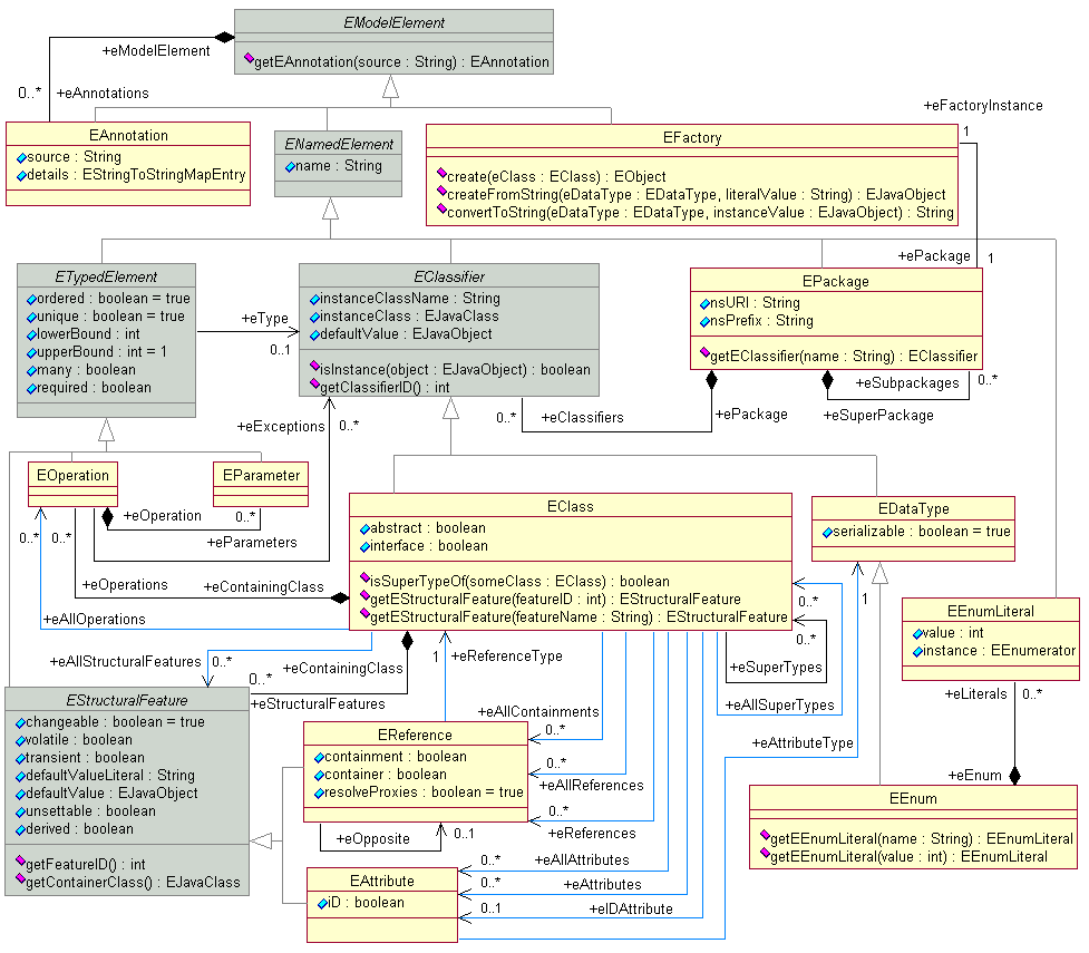
Author information
Authors and Affiliations
Corresponding author
Editor information
Editors and Affiliations
Rights and permissions
Copyright information
© 2017 Springer Science+Business Media Dordrecht
About this entry
Cite this entry
Ecker, W., Schreiner, J. (2017). Metamodeling and Code Generation in the Hardware/Software Interface Domain. In: Ha, S., Teich, J. (eds) Handbook of Hardware/Software Codesign. Springer, Dordrecht. https://doi.org/10.1007/978-94-017-7267-9_32
Download citation
DOI: https://doi.org/10.1007/978-94-017-7267-9_32
Published:
Publisher Name: Springer, Dordrecht
Print ISBN: 978-94-017-7266-2
Online ISBN: 978-94-017-7267-9
eBook Packages: EngineeringReference Module Computer Science and Engineering