
Abstract
The paper presents the definition of the design pattern language of Smart Cities in the form of an ontology. Since the implementation of a Smart City system is difficult, expensive and closely linked with the problems concerning a given city, the knowledge acquired during a single implementation is extremely valuable. The language we defined supports the management of such knowledge as it allows for the expression of a solution which, based on best practices recorded in the form of design patterns, is also tailored to the requirements of the city seeking to implement the Smart City solution. The formal/ontological structure of the language in turn allows the automatic management of the properties of a solution recorded in this way. This final feature of the introduced language is extremely important in the decision-making process regarding the choice of a particular solution by the relevant authorities.
The work is divided into five main parts. In the first part we discuss the implementation issue of the integration bus using the example of the IOC. In the next part we talk about the validity of using semantic technologies in order to expand the spectrum of potential implementations. Then we discuss the ontological implementation of the Smart City pattern language which we created, a language which allows for both the saving of requirements and the validation of solutions specified in it. We also present an example of usage, which at the same time serves as a validation of the language in real-life conditions. In the last part we discuss certain aspects of the pattern language and the possible ways to develop research related to it.
Access provided by Autonomous University of Puebla. Download chapter PDF
Keywords
- Smart cities
- Ontologies
- Semantics
- Ontology driven architecture
- Design patterns
- Controlled natural language
1 Introduction
The concept of a Smart City promises the achievement of a new quality of city management by integrating ICT structures available in the city and by their expansion into other urban areas. The integration of these structures is carried out through the appropriate implementation of a common, scalable and highly-efficient integration bus, such as the IBM Intelligent Operations Center [2]. Such a bus, being indirectly integrated with the urban space becomes part of it and thus designing the implementation process for the integration bus is highly complicated and expensive. To reduce the costs of further implementations, it should be possible to repeat this process. Due to the diversity of urban areas, such repeatability cannot, however, involve copying successful implementations in full, but rather means the selection of the best combination of best practices, adapted to particular specifics, and then the verification (a priori) of the resulting solution as a whole. The desired selection method of the implementation of the Smart City integration bus should allow for:
-
1.
cataloging of previously developed best practices,
-
2.
verification of the expected results of the implementation.
In this paper, we present a method we developed to manage the Smart City integration bus implementation experience which meets both conditions. It is based on the so-called Smart City pattern language, recorded in the form of an IT ontology. This language is equipped with all language layers:
-
1.
The syntactic layer (and grammar) is provided by a network of possible solutions, which pattern language fits into, patterns become the words in the pattern language.
-
2.
The semantics of the pattern language is defined by the limitations/opportunities of the mutual interlacing (depending on each other) of patterns
-
3.
The pragmatic layer is carried out by appropriately selected tools enabling work with the language. For this reason, we have implemented a key tool (OntoTransTool) allowing for the integration of the semantic technologies with the existing solution for the configuration of the Smart City.
We also describe the verification results of the method using the example of implementing the Smart City integration bus based on the IBM IOC integration bus in Gdansk.
2 The Issue of Implementing the Smart City Integration Bus Based on the Example of the IBM Intelligent Operations Center
In this section, we describe the implementation of the Smart City integration bus based on the example of the IBM Intelligent Operations Center (IBM IOC). The IBM IOC integration bus allows for highly efficient processing of data streams and provides tools for their integration. The implementation of IBM IOC takes place on two levels, a low level - the integration bus level (Fig. 1) and at a high level - the model level (Fig. 2). The two-level process of implementation of IBM IOC, described in this section, is the starting point for extending the implementation process with the ontology level that we propose, which will eventually become the environment to which the proposed Smart City pattern language refers.

Sample configuration of the Smart City at the integration bus level (in the M0 MOF layer).

Sample Smart City configuration at the model level (M1 MOF layer)
The integration bus level allows direct access to the services provided by IBM IOC. Figure 1 illustrates an exemplary implementation of IBM IOC seen from this level. We can see here that the processing of data within the IBM IOC bus is carried out in real time via data streams (DataSource) and the results of processing these streams become the basis for determining key performance indicators KPIs. These indicators are presented to bus operators in the form of an intuitive user interface (Client), both in the form of reports (Report) as well as on a map (Spatial, GIS service) so that they can support them in decision-making. The system also integrates the work of operators through an integrated organization management system, such as workflow (carried out by a set of procedures - Simple Operational Procedure - SOP) and through ICT tools for the direct communication of operators (Messaging Service). A hierarchy of privileges built into the system (Responsibility Matrix) together with the security system (Security) allows the mapping of the actual hierarchy of responsibility.
The integration bus level gives access to the greatest potential of configuration, however, the target configuration is difficult to maintain from the perspective of this level and thus requires skilled IT staff. A configuration of processes such as workflow can be an example here: the flow of documentation and the implementation of the responsibility escalation path at this level requires the entire process to be defined in the form of single SOPs, one of which can launch others by generating chains of launching rules. Amongst all the SOPs, the overall picture of the process is less visible.
In contrast to the bus level, the model level captures the IBM IOC configuration from the perspective of the processes which it is to carry out. It is a natural method for analysts and managers, allowing a certain degree of generality for capturing the holistic aspects of implementation difficult to see from the integration bus level. Modeling at this level takes place in the IBM Business Modeler tool in Business Process Modeling Notation (BPMN) language [14]. The example of the IBM IOC configuration at this level is shown in Fig. 2. This shows both the organizational structure (Organizations), report templates and query definitions as well as (unlike at the bus level) the full structure of workflow processes, together with assigning the relevant participants taking part in them, including messages passing between them.
The model level, however, does not provide full configuration options available from the integration bus level, such as the ability to connect any (external data sources), so the most common configuration of the IOC bus consist of two phases (Fig. 3). The perspective of the integration bus level, generated from the model level, is then supplemented with necessary components and is ultimately implemented at the target IOC infrastructure level. This process takes place according to the rules of model transformation in terms of Model Driven Architecture (MDA). The MDA architecture called Meta-Object Facility (MOF) was introduced in 2001 by the Object Management Group (OMG) and is the result of the evolution of object-oriented modeling methods, in particular based on UML.

IOC bus configuration process: the transition from the model level through the integration bus level
IBM IOC carries out the MOF architecture. MOF is designed as a four-layer architecture of models, each of which is more general than the previous one. The layers are called: M3, M2, M1 and M0. From the point of view of the IOC, the integration bus level corresponds to layer M0, while the model level to layer M1 (Figs. 1 and 2). The models are essentially networks of interconnected entities, which in turn (the entities) refer to phenomena occurring in a particular domain [4]. Since the models in MOF are represented by graphs, the languages allowing the processing of models are graph transformation languages [16]. In MOF, the transition from the meta-model (a model from a higher layer) to the model occurs via model transformations called Queries/Views/Transformations (QVT) indicated schematically in the figure (Fig. 3).
To sum up: IBM IOC provides the infrastructures and supports the implementation process of the above-mentioned integration bus infrastructure. The support takes place on two levels. At the model level (M1 as referred to in MOF) and the integration bus level (M0 in MOF). During the configuration of the IBM IOC implementation, from the perspective of the model level, we are equipped with a powerful tool for modeling business processes. In addition, at this level we have the ability to model a high-level organizational structure. After the transformation from the model level onto the integration bus level, a full spectrum of opportunities for integration opens up to us.
At this point, it is worth pointing out a serious limitation of the presented method to support the implementation process of the integration bus. There is no possibility to save the knowledge about the area/domain which a given implementation of IBM IOC refers to and thus models of processes and organizations remain isolated from the specifics of the problem described by them. This is a serious limitation, since it prevents the full integration of knowledge about the implementation. The knowledge about the area/domain/problem in the above-mentioned approach is the knowledge that needs to be stored/processed in external systems.
In the next section we indicate an extension method of knowledge representation used in IBM IOC at the ontology level and we will identify tools for its integration with the existing solution.
3 Ontologies and a Controlled Natural Language in the Design Process of Smart Cities Systems
In the previous section we discussed the current market approach to designing the implementation of the Smart City based on IBM IOC. We have also pointed to an important limitation of the above approach which prevents the full integration of knowledge about the solution with the knowledge of the area/domain/problem the solution refers to. In this section, we show that the integration of semantic methods with a two-level IBM IOC configuration process, can fill this gap. Thus, we will create another level of the integration bus configuration - the ontology level. The section will be concluded with an introduction to modern methods of expressing knowledge in the form of (controlled) natural language, and we will describe a tool for integrating the ontology level with the other two levels of implementation of the IBM IOC integration bus. The resulting extension will become the tool basis for the Smart City pattern language described in the next section - a language allowing for a component-based decomposition of the combinatorial space of possible implementation solutions of the integration bus.
In the previous section we spoke of the MDA architecture called MOF which comes with IBM IOC, and we defined it as a four-layer architecture of meta-models. As shown in the figure (Fig. 4), the metameta-model referred to as M3 is the most general description of the world of models in MOF, it is the definition of the basic concepts of MOF. The M2 layer is a model of modeling languages such as UML or BPMN. M1 refers to models stored in the above-mentioned modeling languages, while M0 is the model proper that relates directly to the modeled world.

General Meta-Object Facility architecture
The MOF M2 layer that defines the modeling languages (and concepts such as class, attribute, relationship or process) and the M3 layer that defines the most abstract concepts (such as the notion of being a subclass, the notion of being a relationship or being a specific part of the class/set - an instance) appear to be common also for semantic technologies from the W3C Semantic Initiative family. OWL [8] is integrated with MOF through the assignment of UML elements (M2 layer) to the corresponding OWL elements and the direct indication of the M3 layer representation in the basic OWL concepts.
It is thanks to the existence of the appropriate concepts between MOF and OWL that it is possible to extend the two-level IBM IOC configuration process (based on MOF) with the OWL semantic methods - methods which enable the recording of knowledge in the form of an ontology. Ontologies are tools to record knowledge about the area/domain/problem described by the implementation of the IOC integration bus. Moreover, in this way (having the above extension) we also extend our range of tools (until now they were the graph transformation languages) with systems for proving theorems (reasoners) operating in the formalism of the SROIQ narrative logic [7, 9]. An official responsible for the implementation of a given solution, with the help of the reasoner, may find the confirmation that a given solution is useful in the context of a given area/domain/problem.
By applying a combination of MOF and OWL in the implementation of the IOC IBM bus, we add another level of the IOC bus implementation - the ontology level (O), while the implementation is extended with the model materialization stage on the basis of the ontology (Fig. 5).

Materialization of the model level (M1) on the basis of an ontology (O)
Materialization is performed based on the reasoner and allows moving from the ontology level to the model level similarly to the way the QVT transformation works in the case of the transition from the model to the integration bus level in the standard approach supported by IBM IOC. However, while during the transition from the model level to the bus level we deal with a transformation of graphs, the tool we created for carrying out the transformation (OntoTransTool) materializes the graph of the model level on the basis of the theory (ontology) recorded in narrative logic (of the formal database OWL). OntoTransTool, as input, accepts the ontology and on its basis generates an input file for the IBM Business Modeler (see Fig. 6) - (IBM Business Modeler is a tool, mentioned in the previous section, which is used to model the IBM IOC implementation from the level of the model - see Fig. 2).

Materialization of the M2 model from the ontology level (O) with the use of OntoTransTool
The next step after the integration of the ontology level with the two-level implementation process of the IOC integration bus is to select a tool for modeling ontology this at level. The best known tool for modeling ontology is Protégé, developed by Stanford University [13]. Protégé enables the creation and debugging of an ontology. It is equipped with a graphical user interface that allows the editing of an ontology in the interaction mode. We tried to use this tool as a tool for modeling at the ontology level (see Fig. 7). Unfortunately, its user requires the appropriate training. To understand the knowledge the user needs to learn the knowledge engineering methods used in the tool - which, unfortunately, in practice prevents the use of this tool in conducting dialogue with people interested in the implementation of the Smart City solution (they are not usually interested in the aspects of engineering knowledge).

Example configuration of the Smart City modeled on the ontology level (layer O) in Protégé
On the other hand, the opportunity to consult the ontology with interested parties is important for several reasons:
-
1.
The client is involved in the configuration process - the client has a real impact not only on the requirements but also on the shape of the solution - which increases the chances of success
-
2.
Ontology elements can be attached to the contract binding the person ordering a given IBM IOC implementation with the provider of the platform
-
3.
The client has a chance to verify solutions (a priori) and thus has some evidence proving the correctness of decisions taken personally as early as at the design stage of implementation.
The above mentioned communication barrier regarding tool support is largely eliminated by so-called natural user interfaces - in particular, interfaces in the form similar to a natural language. This seems obvious (all people regardless of their field communicate in a natural language) and in the context of expressing an ontology, through the use of controlled natural languages (CNL) this was pointed out, among others, by Kuhn [11]; however, - as we will show in the section on implementation - often the natural language loses to graphical knowledge representation languages. In particular, graphical languages to record business processes such as BPMN - allowing for the representation of a process in the form of a graph - are easier to acquire for humans than their representation in a natural language. This graphical feature of languages recording business processes made us realize that it is worth reusing artifacts that naturally arise at the level of the model during the modeling of an ontology. There was a need to develop bilateral transformation - both from the ontology level to the model level and from the model level to the ontology level which is also provided by OntoTransTool, which we implemented.
Fluent Editor is a tool for modeling ontologies in a natural language [3]. Ontologies stored in Fluent Editor are equivalent with ontologies stored in Protégé as both tools operate in the OWL technology, although in Protégé we are dealing with a graphical user interface, while in Fluent Editor ontologies are presented in the form of a document in a natural language. Including Fluent Editor in the set of tools to support the IOC configuration, we received the ability to record knowledge about the area/domain/problem related to the implementation in a natural language (see Fig. 8). Figure 8 shows Fluent Editor loaded with the ontology of an example which we will discuss later in this paper.

Sample configuration of the Smart City modeled at the ontology level (layer O) in the Ontorion Fluent Editor tool.
To sum up: IBM IOC provides tools for the two-level integration bus implementation but ignores the aspect of integrating knowledge about the area/domain which a given implementation refers to and hence often (due to lack of tool support) models of processes and organizations remain in isolation from the specifics of the problems they describe. The third level we introduced - the ontology level - fills this gap. The modeling on the ontology level is performed with the use of controlled natural language, allowing for the direct use of ontologies saved in it to communicate with the client of the system. The integration of the ontology level is accomplished due to a tool we created, called OntoTransTool, which provides the possibility to materialize the ontology to the level of the model.
In the next section we introduce an ontological Smart City pattern language, based on the created tool database, which allows the decomposition of the combinatorial space of the possible implementation solutions of the integration bus and thus enables effective reuse of best design practices emerging during the work of experts.
4 Implementation of the Pattern Language for the Smart City
In the previous section we introduced the ontology level to the two-level implementation process of the IBM IOC integration bus. The ontology level allows the expression of knowledge about the area/domain/problem which a given implementation of the IBM IOC integration bus refers to in a manner consistent with the other two levels. The question arises - how to construct ontologies at this level in an optimal way. In the introduction, we set out to strive and create a tool which will enable the reuse of valuable expert knowledge regarding implementations. The best tool for this purpose, as proven by their growing popularity, are pattern languages.
Christopher Alexander [1] noted that cities are based on patterns. Currently, design patterns are a commonly used structure for exchanging solutions to recurrent problems. They are present in literature concerning urban planning (where they originated), information technology, pedagogy and many others. Alexander also notes that cataloging patterns creates a new value in the form of a language of patterns. A language, the words of which are names of individual patterns. At the same time, the pattern language allowing the resolution of problems which are combinations of simpler problems described by patterns-words, becomes a pattern: a pattern-language. A pattern is defined today as a method of documenting a solution of a recurrent design problem within a specific domain. In 1995, Gamma, Helm, Johnson and Vlissides [5] published the first directory of software design patterns, applying the ideas of Alexander to the field of software engineering.
One of the first attempts to formalize pattern languages can be found in a publication by Meszaros [12], in which we can find a self-definition of pattern language, as a pattern for creating more complicated patterns. This publication has become an inspiration to us and as such has given us a strong foundation to create a formal meta-language of patterns. We undertook to transpose the “patterns of writing patterns” described in the work of Meszaros onto the formalism of saving an ontology. The vehicle which allowed us to do so is controlled natural language.
It is worth focusing here on the language for recording an ontology - the controlled language which takes the form of a text file in Fluent Editor. Individual assertions (axioms) are separated with a period (.) and can be divided into a few basic groups:
-
1.
Concept subsumption represents all cases where there is a need to specify (or constrain) the fact about a specific concept or instance (or expressions that evaluate the concept or instance) in the form of subsumption (e.g.: Every cat is a mammal, Pawel has two legs or One cat that is brown has red eyes).
-
2.
Role (possibly complex) inclusion specifies the properties and relationships between roles in terms of the expressiveness of SROIQ(D) (e.g.: If X loves something that covers Y then X loves-cover-of Y).
-
3.
Complex rules; If [body] then [head] expressions that are restricted to the DL-Safe SWRL subset [Fig. 1] of rules (e.g.: If a scrum-master is-mapped-to a provider and the scrum-master has-streamlining-assessment-processes-sprints-level equal-to 2 then the provider has-service-delivery-level equal-to 1 and the provider has-support-services-level equal-to 2).
-
4.
Complex OWL expressions; the grammar allows the use of parentheses that can be nested if needed in the form of (that) e.g.: Every human is something (that is a man or a woman or a hermaphrodite).
-
5.
Modal Expressions allow the expression of “knowledge about the knowledge” with CNL. This is to enforce fulfilling several properties of the knowledge. There are six modal words that can be used: must, should, can, must-not, should-not, can-not. All instances that are subject to validation against modal expressions are highlighted in Fluent Editor. Green means all requirements are fulfilled. Red means there is some requirement not met. Yellow means a warning. It appears when requirements with the “should” expression are not fulfilled. Light yellow means there is nothing wrong but it is marked just for informing the users. For example, regarding the statement “Every man can have a wife.” - there is nothing wrong if there is a man that does not have a wife. For each modal expression different colors will appear as below:
-
I.
X must Y (e.g. Every X must also Y) – if not, it will be marked in red.
-
II.
X should Y (e.g. Every X should also Y) – if not, it will be marked in yellow.
-
III.
X can Y (e.g. Every X can also Y) – if not, it will be marked in light yellow.
-
IV.
X can-not Y (e.g. Every X cannot also Y) – if it is, then it will be marked in red.
-
V.
X should-not Y (e.g. Every X should not also Y) – if it is, then it will be marked in yellow.
-
VI.
X must-not Y (e.g. Every X must not also Y) – if it is, then it will be marked in light yellow.
-
I.
The pattern language having the form of an ontology becomes a tool for managing trust towards the considered solution which is stored in it. It allows the application of computer methods as an important participant, which eliminates many errors generated by the “human factor.” The ontology of the design pattern language should be self-describing, thus we shall start with the definition of basic concepts. The following example illustrates the use of a controlled language on the basis of a definition in the form of a pattern ontology “pattern” as well as a pattern “pattern language.” The target structure of the ontology of the design pattern language is schematically drawn in Fig. 9. The pattern is defined here as a way to represent knowledge about solving the problem, it works in a certain context and resolves certain strengths prioritized by the above context. The pattern language meets the definition of a pattern (it is a pattern), solving a complex issue through a network of interrelated patterns.

Ontology structure of the design pattern language of the Smart City
Let us move on to the detailed record of the ontology structure of the pattern language, which is schematically illustrated in Fig. 9. Since we rely here on the taxonomy introduced by Meszaros, direct quotations from [12] are placed within single quotation marks. Please note the self-descriptive nature of the description of the structure in the controlled natural language.
-
§1.
The problem that has-description equal-to ‘How do you share a recurring solution to a problem with others so that it may be reused? ’ is solved by Pattern-Pattern.
-
§2.
Every pattern solves at-most one problem.
It is worth noting that the element describing the pattern-pattern solution requires the use (after Meszaros) of another pattern: the pattern of mandatory elements - here also direct quotations from [12] are included within single quotation marks.
-
§3.
The problem that has-description equal-to ‘ How do you make sure that all necessary information is covered in a pattern? ’ is solved by Mandatory-Elements-Present-Pattern.
The requirement as to the pattern format (which includes context, strength, solution and problem) manifests itself in the line below, in which we indicate by means of a modal expression that each model must carry out mandatory elements.
-
§4.
Every pattern must realize Mandatory-Elements.
In turn, we point to the solution regarding the pattern of mandatory elements - indicating explicitly which elements must be included in the design pattern for it to be the pattern of mandatory elements.
-
§5.
If a pattern solves a problem and the pattern resolves a force and the pattern has-name (some string value) and the pattern operates-in a context and the context prioritizes the force then the pattern realizes Mandatory-Elements.
We shall write down the solution offered by the pattern-pattern using the modal structure “should”. The limitation it poses onto knowledge is ambiguous (sic) - in other words: we accept - as the creators of the specification - the possibility of breaking the contract, leaving the language user the freedom of choice. The language user breaking our recommendation will, however, be warned of the above violation:
-
§6.
Every pattern should solve a problem.
-
§7.
Every pattern should resolve a force.
-
§8.
Every pattern should operate-in a context.
-
§9.
Every pattern should have-name (some string value).
-
§10.
Every context should prioritize a force.
The effect of the above recommendation will be demonstrated when defining the pattern language of the Smart City, but before we define the abstract pattern language (which is also a pattern) - direct quotations from [12] are included within single quotation marks.
-
§11.
Pattern-Language-Pattern solves the problem that has-description equal-to ‘How do you describe the solution such that it is easy to digest and easy to use parts of the solution in different circumstances? ’.
Pattern “language-patterns” as defined above generate a class of language patterns defined below, at the same time we require (it is mandatory) that it implements the pattern “language-pattern”:
-
§12.
Every pattern-language is a pattern.
-
§13.
Every pattern-language must implement Pattern-Language-Pattern.
We require/ask (it is not mandatory) for the pattern language to be equipped with a syntactic layer manifested through the dictionary:
-
§14.
Every pattern-language should use a pattern-dictionary.
And so it solves (again it is not mandatory) a complex problem. In addition, we define what we mean by the term “a complex problem”:
-
§15.
Every pattern-language must solve a complex-problem.
-
§16.
If a problem(1) is-part-of a problem(2) then the problem(2) is a complex-problem.
And we indicate that compliance with our requests will result in the fulfillment of the mandatory requirement.
-
§17.
If a pattern-language uses a pattern-dictionary and the pattern-language solves a complex-problem then the pattern-language implements Pattern-Language-Pattern.
Having defined abstract concepts, which are on a high-level conceptual basis, we can finally move on to the definition of a specific pattern language that will be adapted to the needs of the ontology level of the design and implementation process of the IBM IOC integration bus. And thus we define in the controlled language as follows:
-
§18.
Smart-City-Pattern-Language is a pattern-language and operates-in Context-Of-Smart-City-Pattern-Language and has-name equal-to ‘ Smart City Pattern Language ’.
-
§19.
Context-Of-Smart-City-Pattern-Language is a context and has-description equal-to ‘A single pattern is insufficient to deal with all Smart City problems at hand. ’.
-
§20.
Smart-City-Pattern-Language solves the problem that has-description equal-to ‘How do you describe the solution for Smart City such that it is easy to digest and easy to use parts of the solution in areas of: a)People-First b)Business-Attractive c)Green d)Cheap (PBGC)’.
-
§21.
The force that has-description equal-to ‘A single large Smart City solution may be too specific to the circumstance and impossible to reuse in other circumstances.’ is resolved by Smart-City-Pattern-Language and is prioritized by Context-Of-Smart-City-Pattern-Language.
-
§22.
The force that has-description equal-to ‘A complex Smart City solution may be hard to describe in a single pattern. A “divide and conquer” approach may be necessary to make the solution tractable.’ is resolved by Smart-City-Pattern-Language and is prioritized by Context-Of-Smart-City-Pattern-Language.
-
§23.
The force that has-description equal-to ‘Factoring the Smart City solution into a set of reusable steps can be very difficult. Once factored, the resulting pieces may depend on one another to make any sense.’ is resolved by Smart-City-Pattern-Language and is prioritized by Context-Of-Smart-City-Pattern-Language.
-
§24.
The force that has-description equal-to ‘Other pattern languages may want to refer to parts of the Smart City solution; they require some sort of “handle” for each of the parts to be referenced.’ is resolved by Smart-City-Pattern-Language and is prioritized by Context-Of-Smart-City-Pattern-Language.
-
§25.
Smart-City-Pattern-Dictionary is a pattern-dictionary.
-
§26.
Smart-City-Pattern-Language uses Smart-City-Pattern-Dictionary.
Above we defined the notion of the Smart City pattern language. The Smart City pattern language is a pattern that allows complex problems to be solved, which cannot be solved with a single pattern. The pattern language solves the problem of implementing a complex Smart City solution. The knowledge engineer operating in the ontology layer has the ability to use the Smart City pattern language, with concepts representing particular patterns. He is “protected” from its misuse by modal expressions (mandatory orders, requests or suggestions) included in the “pattern metalanguage”.
To illustrate the work of the pattern language in practice, we shall define two patterns, and we will use them in an exemplary implementation. These will be patterns which occur commonly and naturally in all the cities, responding to real, common problems.
-
(1)
Hierarchy of responsibility
-
(2)
Man In The Loop-Resource conflict solver.
Of course these are only two from a whole spectrum of design patterns. So far we have managed to catalog ten patterns, however, a detailed description of all of the cataloged patterns goes beyond the scope of this paper. We shall list them in name only:
-
(3)
Agregate KPIs,
-
(4)
Mapping the KPIs,
-
(5)
Predicting KPIs,
-
(6)
Administrative SOP,
-
(7)
Smart-Monitoring,
-
(8)
Vectorization of streams,
-
(9)
Social monitoring channel,
-
(10)
Dynamic road sign.
Two patterns which will be described in detail were selected because of their subsequent use in the validation of the pattern language in a sample real implementation of the IBM IOC configuration bus.
4.1 Smart City Pattern: Hierarchy of Responsibility
The first pattern to be described here solves a key problem from the point of view of the city - the problem of responsibility for decisions. In this section we will show how the Smart City pattern language should be used for the purpose of expressing knowledge about a known and commonly acceptable solution to a given problem, in the form of a pattern. We operate at the ontology level of the extended configuration process of the IBM IOC integration bus.
The city is managed by the relevant authorities. The most common approach to city management is a hierarchy of responsibility. By establishing rules of communication flow, the hierarchy improves delegating tasks. Below there is a “hierarchy of responsibility” pattern. It is a part of the Smart City dictionary and it is also a problem that is solved by the Smart City Pattern Language Patterns:
-
§27.
Context-Of-Hierarchy-Of-Responsibility-Pattern is a context and has-description equal-to ‘ Bez hierarchii przepływu oraz możliwości eskalacji problemu jest trudno zarządzać miastem ’.
-
§28.
Hierarchy-Of-Responsibility-Pattern is a pattern and operates-in Context-Of-Hierarchy-Of-Responsibility-Pattern and has-name equal-to ‘ Hierarchy Of Responsibility ’ and solves the problem that has-description equal-to ‘ Jak ułożyć hierarchię przepływu decyzji oraz eskalacji problemów? ’ and is-part-of Smart-City-Pattern-Dictionary.
-
§29.
The problem that is solved by Hierarchy-Of-Responsibility-Pattern is-part-of the problem that is solved by Smart-City-Pattern-Language.
-
§30.
The force that has-description equal-to ‘ często kompetencje urzędow są zduplikowane lub niejednoznacznie określone ’ is resolved by Hierarchy-Of-Responsibility-Pattern and is prioritized by Context-Of-Hierarchy-Of-Responsibility-Pattern.
The solution to this pattern requires defining a few truths. And so:
-
§31.
Every-single-thing that manages is a management.
-
§32.
Every city must be managed by.
-
§33.
Every smart-city is a city.
-
§34.
Every smart-management is a management.
We require that a Smart City is managed by a smart-management.
-
§35.
Every smart-city must be managed by a smart-management.
-
§36.
Every management that manages a smart-city must be a smart-management.
In addition, we show that the use of this pattern will result in the realization of the mandatory requirement.
-
§37.
If a management implements Hierarchy-Of-Responsibility-Pattern then the management is a smart-management.
This sentence above (see §37) seems to be an oversimplification. Here, in order to validate a mandatory part correctly it is enough to declare its implementation (e.g. by stating: Management-X implements Hierarchy-Of-Responsibility-Pattern). However, the person who enters such a sentence becomes responsible for the explanation of how they managed to do it. Therefore it is also required that:
-
§38.
Every management that implements Hierarchy-Of-Responsibility-Pattern must provide-implementation-details (some ontology-reference value).
This forces the language user to justify the implementation of a given pattern. Going further, we can expand our requirements regarding the conditions under which we agree to the pattern being deemed as fulfilled: e.g. the verification of certain properties of the pattern that it must meet. In this paper, however, we keep the current approach, which is the simplest.
Let us add that a city managed using the pattern “Hierarchy-Of-Responsibility” is a city where there is an escalation of problems. It will be important in view of the next model, which requires that such an escalation is possible:
-
§39.
If a management implements Hierarchy-Of-Responsibility-Pattern then the management is a smart-management and the management is an escalator-based-management.
The above example shows how patterns become interlaced in the pattern language. Patterns are not dependent on each other directly, but conceptually - they are intertwined at the level of concepts. As a result, some patterns “fit” to other patterns while others do not, and using the pattern language (its pragmatics) looks like matching suitable blocks from the set.
4.2 Smart City Pattern: Man-in-the-Loop-Resource-Resolver
Another significant problem that every city must face is the problem of limited resources. In this section we will present a solution to this recurrent problem, which is most commonly implemented. We also operate at the ontology level of the extended configuration process of the IBM IOC integration bus.
Conflicts arising during emergencies are associated with attempts to use limited resources in the context of the temporal coincidence of many emergencies. In particular, the interweaving of the same resources among equal domains can (in the event of a conflict) lead to a situation requiring the “best possible” decision to be taken swiftly. The Man-In-The-Loop-Resource-Resolver pattern solves this problem by inserting a person into the decision-making process, who must assume responsibility for the decision. The person, however, is not alone, since the pattern finds the existence of an environment to raise escalation mandatory - such an environment is for example created by the Hierarchy of Responsibility pattern discussed earlier. This pattern is a part of the Smart City dictionary that we created and is a problem that is solved by the Smart City Pattern Language Patterns:
-
§40.
Context-Of-Man-In-The-Loop-Resource-Resolver-Pattern is a context and has-description equal-to ‘ Smart - City wymaga zamodelowania kilku domen, wszystkie ww. domeny współdzielą ograniczone zasoby ’.
-
§41.
Man-In-The-Loop-Resource-Resolver-Pattern is a pattern and operates-in Context-Of-Man-In-The-Loop-Resource-Resolver-Pattern and has-name equal-to ‘ Man In The Loop Resource Resolver ’ and solves the problem that has-description equal-to ‘ W jaki sposób współdzielić ograniczne zasoby między rózne domeny? ’ and is-part-of Smart-City-Pattern-Dictionary.
-
§42.
The problem that is solved by Man-In-The-Loop-Resource-Resolver-Pattern is-part-of the problem that is solved by Smart-City-Pattern-Language.
-
§43.
The force that has-description equal-to ‘ Efektywne zarządzenie zasobami wymaga wiedzy eksperckiej ’ is resolved by Man-In-The-Loop-Resource-Resolver-Pattern and is prioritized by Context-Of-Man-In-The-Loop-Resource-Resolver-Pattern.
-
§44.
The force that has-description equal-to ‘ Niekiedy decyzje o przydziale zasobów wymagają zaangażowania wielu osób ’ is resolved by Man-In-The-Loop-Resource-Resolver-Pattern and is prioritized by Context-Of-Man-In-The-Loop-Resource-Resolver-Pattern.
Below we present the definition of a city fragile to shared resources:
-
§45.
Every-single-thing that is dealt-with by something is a domain.
-
§46.
Every-single-thing that is used-resource by something is a resource.
-
§47.
If a smart-city deals-with a domain(1) and the smart-city deals-with a domain(2) and the domain(1) is-not-the-same-as the domain(2) and the domain(1) uses-resource a resource(1) and the domain(2) uses-resource a resource(2) and the resource(1) is-the-same-as the resource(2) then the smart-city is a resource-fragile-smart-city.
It is required that the city management (which decides to deploy the above pattern) could escalate problems:
-
§48.
Every management that manages a smart-city that implements Man-In-The-Loop-Resource-Resolver-Pattern must be an escalator-based-management.
-
§49.
Every resource-fragile-smart-city can implement Man-In-The-Loop-Resource-Resolver-Pattern.
We define a condition the fulfillment of which will balance the shared city resources.
-
§50.
Every resource-fragile-smart-city must be a resource-balanced-smart-city.
And we confirm the correctness of the solution provided by the above pattern. By implementing the above pattern, the city will be a balanced city.
-
§51.
Every smart-city that implements Man-In-The-Loop-Resource-Resolver-Pattern is a resource-balanced-smart-city.
And as it was for the “Hierarchy of Responsibility” pattern, we require the details of the implementation of the solution to be provided:
-
§52.
Every smart-city that implements Man-In-The-Loop-Resource-Resolver-Pattern must provide-implementation-details (some ontology-reference value).
To sum up, we presented the Smart City pattern language and presented two selected patterns in detail. These patterns have been selected due to their subsequent use in the validation of the pattern language. The validation will be conducted in the next section.
Examples of use of the Smart City pattern language.
The formalism presented above may be treated as a tool for selecting best practices-patterns from a directory. The key element of the pattern (which determines its existence) is the solution it has to offer. Patterns suggest these solutions and present their specification. The actual (real) implementation of a pattern must comply with the recommendation to be compatible with it. In other words: the art of using design patterns is the ability to select them, and - more importantly - the ability to materialize them - to fulfill them. Below there is an example of materializing the above-mentioned patterns.
We consider an example deployment of a Smart City in Gdansk. We declare as follows:
-
§53.
Gdansk is managed by Gdansk-Government.
-
§54.
Gdansk is a smart-city.
And by verifying the received knowledge – Gdańsk shimmers red (Fig. 10).

Verification errors of the declared need for implementing the Smart City for the city of Gdansk
It turns out, in line with previous findings that: “Every smart-city must be managed by a smart-management.”
We know that:
-
§55.
Gdansk-Government is a local-government.
-
§56.
Gdansk-Government implements Hierarchy-Of-Responsibility-Pattern.
Re-validation indicates the need to justify the implementation of the pattern (Fig. 11).

Declaration of the implementation of the Smart City for the city of Gdansk after the information is provided about the type of pattern adopted for the management of the city
We will conduct the justification in a separate file describing the hierarchy and we will identify this file as a place where the aforementioned justification can be found. The first step is the correct location of the Smart-City management - in this case it is the Gdansk-Municipal-Crisis-Centre
-
§57.
Gdansk-Government is Gdansk-Municipal-Crisis-Centre[hier].
Going further:
-
§58.
Voivodship-Executive-Board is-part-of Local-Government.
-
§59.
Chief-Inspectorate-Of-Environmental-Protection is-part-of Voivodship
-
§60.
Inspectorate-For-Environmental-Protection.
-
§61.
Directors-Of-Health-Care-Facilities is-part-of The-“NZOZ”.
-
§62.
Directors-Of-Health-Care-Facilities is-part-of Local-Government.
-
§63.
Directors-Of-Educational-Institutions is-part-of Local-Government.
-
§64.
Directors-Of-Care-Facilities is-part-of Local-Government.
-
§65.
Airport-Fire-Brigade is-part-of Airport.
-
§66.
City-Fire-Brigade is-part-of Provincial-Office.
-
§67.
Airport-Medical-Care is-part-of Airport.
The hierarchy defined in such a way also requires the definition of methods regarding the escalation of problems. For this purpose we will create two new entities:
-
§68.
Every notified-body is an organization.
-
§69.
Every notifying-body is an organization.
And we will assign them to the above-mentioned hierarchy along with other entities taking part in a given scenario:
-
§70.
Directors-Of-Hospitals is a notified-body.
-
§71.
Pilot is a notifying-body.
-
§72.
Airport is a notified-body.
-
§73.
Airline is a notified-body.
-
§74.
Police is a notified-body.
-
§75.
Directors-Of-Health-Care-Facilities is a notified-body.
-
§76.
Directors-Of-Educational-Institutions is a notified-body.
-
§77.
City-Fire-Brigade is a notified-body.
-
§78.
Voivodship-Crisis-Centre is a notified-body.
-
§79.
Voivodship-Executive-Board is a notified-body.
-
§80.
Chief-Inspectorate-Of-Environmental-Protection is a notified-body.
-
§81.
Local-Government is a notified-body.
-
§82.
Local-Radio is a notified-body.
-
§83.
Local-Television is a notified-body.
This pattern implementation is contained in the described ontology “hierarchy.encnl”. Typing in the above fact and subjecting the ontology to re-validation we get the green light. Currently, all mandatory requirements imposed on the city and its management are met, since only the city implements the “Hierarchy of Responsibility” pattern (Fig. 12).

Declaration of the implementation of the Smart City for the city of Gdansk after supplementing the information about the type of pattern adopted for the management of the city and indicating the means of its implementation
However, going further, it appears that in Gdansk we deal, among others, with an airport and the problem of air pollution and both of these domains share the need for the resource - Healthcare Facilities:
-
§84.
Gdansk deals-with Airport-Domain.
-
§85.
Gdansk deals-with Air-Pollution-Domain.
-
§86.
Airport-Domain has-name equal-to ‘ Gdansk Airport Domain ’.
-
§87.
Air-Pollution-Domain has-name equal-to ‘ Gdansk Air Pollution Domain ’.
-
§88.
Airport-Domain uses-resource Healthcare-Facilities.
-
§89.
Air-Pollution-Domain uses-resource Healthcare-Facilities.
And in result, Gdańsk becomes resource-fragile (Fig. 13).

Further verification indicates that there is a resource conflict
The solution suggested by the validator is to implement the Man-In-The-Loop-Resource-Resolver-Pattern. The protocols of procedure arise from respective laws and are associated with respective domains. The protocols describe processes that are best presented in the processes modeling language. At this point, we return to the IBM IOC model level, as the modeled processes are at the level of M1 MOF - so it is best if it is supported by a tool for modeling in BPMN, such as the IBM Business Modeler. It appears that the process of IOC configuration is not a one-way process but a process operating in a feedback loop (Fig. 14).

Feedback in the modeling process arising due to the need for process modeling
Of course, this protocol is equivalent to the following (completely unintelligible) record in CNL:
-
§90.
Ev-000 is a start-event.
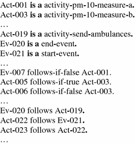

Natural language shows its weakness here. A weakness illustrated in the saying “a picture is worth more than a thousand words”. In this case the saying appears to be true. We can prove here the existing limits of the interface based on natural language - these are the limits of usability, limits that are rediscovered. Richard Riehle in [15] states: “look back at the fascination in all we had with our flowcharting as a gigantic waste of time. Yet, there was a kernel of a linguistic concept in those templates that survives today.” Unfortunately diagrams have a major drawback - they represent networks - graphs - relationships between entities, while natural language sentences represent the workings of the world - they represent the truth that is realized (materialized) in graphs.
Here are two diagrams:
-
1.
The protocol of procedure in the case of excessive levels of PM10 (Fig. 15)
Fig. 15. 
The protocol of procedure in the case of excessive levels of PM10 in BPMN
-
2.
The protocol of procedure in the case of an emergency landing of an aircraft depending on its size (Fig. 16)
Fig. 16. 
The protocol of procedure in the case of emergency landing depending on the size of the aircraft


In constructing a “hierarchy of responsibility,” we had to designate a “trail” of problems escalation. This trail is essential if we want to locate the person who can make decisions in case of a conflict of resources. We assume that the person does it rationally. Since, however, the person’s decisions are rational, they can be substituted by automatic decisions. Proving this thesis requires the use of non-monotonic knowledge management systems (allowing for the removal of conclusions depending on the circumstances), and thus remaining beyond the scope of this paper. It is worth presenting examples of experimental rules written in the non-monotonic formalism. And thus, for our example:
-
§91.
If an agent has-started-activity an activity and the activity is an activity-pm-10-measure-a and the agent has-pm-10-measurement equal-to the value(1) then for the agent and the activity and the value(1) execute

-
§92.
Every activity-pm-10-measure-b is an activity.
-
§93.
If an agent has-started-activity an activity and the activity is an activity-pm-10-measure-b and the agent has-pm-10-measurement equal-to the value(1) then for the agent and the activity and the value(1) execute

-
§94.
Every activity-size-of-plane is an activity.
-
§95.
If an agent has-started-activity an activity and the activity is an activity-size-of-plane and the agent has-size-of-plane equal-to the value(1) then for the agent and the activity and the value(1) execute


Concluding our discussion and saving the above solution in the ‘man-in-the-loop.encnl’ file and declaring in our ontology the above solution as an explanation of the pattern implementation, the validator once more gives us the green light (Fig. 17).

Declaration of the implementation of the Smart City for the city of Gdańsk after supplying information about the type of pattern adopted for resolving the resource conflict and indicating the means of its implementation
To sum up: in this section we presented the validation of the previously introduced pattern language. This validation involved the creation of a configuration ontology of the IBM-IOC integration bus on the basis of the pattern language. A full cycle of work with the pattern language was shown. We found that the cascade model of transition from the ontology (O) to the model level (M1) should be changed by adding a feedback loop, which allows the supplementation of the range of tools with an adequate transformation.
5 Criticism of Design Patterns
Criticism of the design patterns conducted, among others, by Peter NorwigFootnote 1 states that design patterns are solutions to problems generated by the language itself (in which they are stored or which they refer to). In other words - the pattern language tries to compensate for language problems of the language which it reaches - namely it solves the imperfections that the language itself should eliminate. Norwig operates in the world of software, but he is right to present most of the GOF patterns as “artificial problems” in languages such as LISP and Dylan which do not generate such problems. It seems, however, that Norwig, criticising the patterns of software, neglects the attributes of a pattern and identifies the pattern with the solution. However, the pattern remained and remains only a way to exchange experiences regarding solutions to recurring problems. From this point of view, the programming language is an important part of the pattern context and hence Norwig’s criticism can be fended off by stating – the context of GOF patterns does not include languages such as LISP or Dylan.
In our understanding, a pattern is a way of distributing experience. Its specific form, and the number of implementations of the idea of design patterns leads us to believe that the attributes of a pattern are a universal method. What is more - the Smart City pattern language which we introduced is in the form of formal ontologies which can be proved, though it remains only a means to exchange experiences about solutions to common problems. A means - as we are trying to show - worthy of further research.
6 Summary
Designing Smart Cities in its essence is an issue of urban planning as urban structures, the object of study of urban design, allow for the development of the concept of planning. The Smart City implementation project is the realization of a planning concept so it is in line with the aforementioned definition. The Smart City design patterns that we propose are analogous to design patterns in urban planning. In other words, the architecture of the old implementation of the Smart Cities integration bus, following the architecture of the city in which it is implemented, remains the architecture of an IT system. It is therefore a virtual extension of a given city. Applying the discovery of Christopher Alexander in the context of the implementation of the Smart City integration bus, we make a full circle - the patterns again refer to cities, this time, however, they operate on a virtual model/extension of the city.
In this paper, we presented the solution to problems associated with the reuse of extremely valuable knowledge that arises during the implementation of the Smart City integration bus. We proposed the use of a natural language matched to the issue, formally defined and equipped with adequate tools of the Smart City pattern language. What is important, this language gives a very powerful tool to authorities responsible for decisions - the ability to verify the solution by reasoners. The formal methods based on reasoners are the most powerful tool to build confidence in the proposed solution.
On the other hand, since making decisions - such as the decision to choose the configuration of the Smart City integration bus - can be supported by a computer, the question is: whether rational decisions can be made by a machine? Here, unfortunately, for us humans, the answer seems to be positive. The maximum understanding of knowledge “at one time” by humans seems to be indicated by the problem of “driving”. Driving a car requires the knowledge of the Highway Code, the application of that knowledge as well as the ability to make quick operational decisions. On the other hand, as demonstrated by Nobel Prize winner Daniel Kahneman [10], analytical thinking costs people a lot of energy. Assimilation of the “whole” knowledge in a given domain by a human being reaches a certain limit determined by the time required for understanding the knowledge, and the full depth of understanding becomes, in a way, unattainable. Mathematicians can be proof of this, they reason deeply but mathematics itself (at least in comparison with the soft sciences) develops slowly. Theoretically, for computers the time to reach the depth of understanding is much shorter and the processing of knowledge seems to be limited only by the laws of logic. Here PCs gain an advantage over us and the idea of equipping Smart Cities with a solution, such as IBM Watson would seem to be interesting.
Notes
References
Alexander, C., Ishikawa, S., Silverstein, M.: A Pattern Language: Towns, Buildings, Construction (Center for Environmental Structure Series). Oxford University Press, Oxford (1977)
Bhowmick, A.: IBM Intelligent Operations Center for Smarter Cities Administration Guide. IBM Corporation, International Technical Support Organization (2012)
Cognitum: Fluent Editor 2014 - Ontology Editor (2014). http://www.cognitum.eu/semantics/FluentEditor/
Fowler, M.: Patterns of Enterprise Application Architecture (A Martin Fowler Signature Book). Addison-Wesley, Reading (2003)
Gamma, E., Helm, R., Johnson, R., Vlissides, J.: Design Patterns: Elements of Reusable Object-Oriented Software. Addison-Wesley Longman Publishing Co., Inc., Boston (1995)
Glimm, B., Horridge, M., Parsia, B., Patel-Schneider, P.: A syntax for rules in OWL In: Hoekstra, R., Patel-Schneider, P.F. (eds.) OWLED, vol. 529. CEUR Workshop Proceedings (2008). CEUR-WS.org
Goczyła, K.: Ontologie w systemach informatycznych. Akademicka Oficyna Wydawnicza EXIT (2011)
Hitzler, P., Krötzsch, M., Parsia, B., Patel-Schneider, P., Rudolph S.: OWL 2 web ontology language primer. In: W3C Recommendation, World Wide Web Consortium (2009)
Horrocks I., Kutz, O., Sattler, U.: The even more irresistible SROIQ. In: Doherty, P., Mylopoulos, J., Welty, C.A. (eds.) KR, pp. 57–67. AAAI Press (2006)
Kahneman, D.: Thinking, Fast and Slow. Farrar, Straus and Giroux, New York (2011)
Kuhn, T.: How to evaluate controlled natural languages. In: Fuchs, N.E. (ed.) Pre-Proceedings of the Workshop on Controlled Natural Language (CNL 2009), vol. 448. CEUR Workshop Proceedings (2009). CEUR-WS
Meszaros G., Doble, J.: A pattern language for pattern writing. In: Pattern languages of program design 3, pp. 529–574. Addison-Wesley Longman Publishing Co. (1997)
Musem, M, Noy N., Nyulas, C., O’Connor, M., Redmond, T., Tu, S., Tudorache, T., Vendetti, J. and Stanford School of Medicine: Protégé (2010). http://protege.stanford.edu
OMG: Business Process Model and Notation (BPMN), Version 2.0 (2011)
Riehle, R.: Linguistic continuity in software engineering. ACM SIGSOFT Softw. Eng. Notes 31(1), 1–5 (2006)
Rozenberg, G.: Handbook of Graph Grammars and Computing by Graph Transformation: Volume I Foundations. World Scientific Publishing Co., Inc., River Edge (1997)
Author information
Authors and Affiliations
Corresponding author
Editor information
Editors and Affiliations
Rights and permissions
Copyright information
© 2016 Springer-Verlag GmbH Germany
About this chapter
Cite this chapter
Orłowski, C., Ziółkowski, A., Orłowski, A., Kapłański, P., Sitek, T., Pokrzywnicki, W. (2016). Ontology of the Design Pattern Language for Smart Cities Systems. In: Nguyen, N., Kowalczyk, R., Orłowski, C., Ziółkowski, A. (eds) Transactions on Computational Collective Intelligence XXV. Lecture Notes in Computer Science(), vol 9990. Springer, Berlin, Heidelberg. https://doi.org/10.1007/978-3-662-53580-6_6
Download citation
DOI: https://doi.org/10.1007/978-3-662-53580-6_6
Published:
Publisher Name: Springer, Berlin, Heidelberg
Print ISBN: 978-3-662-53579-0
Online ISBN: 978-3-662-53580-6
eBook Packages: Computer ScienceComputer Science (R0)