
Abstract
An instrument able to measure electromagnetic radiation, in its different forms and spectral ranges, is called a radiometer. This chapter focuses on the radiometers used for sensing solar radiation and on the measurements of different components and types of solar irradiance. As a simple classification, we will distinguish between broadband and spectral (narrowband) sensors. First, the fundamentals of physical sensors used to measure solar radiation are briefly described. Then, importance about calibration methods and uncertainty, as well as the structure of the traceability chain in the magnitude of solar irradiance, are presented. Next, solar radiometers and measurement techniques are described, starting from direct radiation in Earth’s surface, global irradiance in horizontal and tilted surfaces, diffuse irradiance, and finally another kind of radiation sensor. This structure is not casual but follows a path similar to that of the traceability chain, starting from the more accurate to the less accurate instruments. There are two additional sections devoted to the measurement of the spectral distribution of irradiance and to the measurement of aerosol contents in the atmosphere by using filter radiometers.
…too little interest is devoted to the calibration of instruments and quality of data. Measurements which are not reliable are useless.
WMO Technical note 172 (1981)
Access provided by Autonomous University of Puebla. Download chapter PDF
1 Sensing Solar Radiation
Instruments measuring solar irradiance are based on the shift of a certain physical property (e.g., an increase in the temperature) in a material or device when solar radiation is impinging in and being absorbed by it. Measurement of this shift allows quantifying the amount of solar irradiance. Therefore, there is no way for a direct measurement of solar radiation, and it is always estimated by an indirect or a two-step method, based well on thermal, or well on photonic effects.
In many cases, thermal detectors of solar radiation have also been used as detectors of infrared radiation (and vice versa). As well, photonic detectors of sunlight have also been used as general optoelectronic sensors of different radiation sources (VIS and UV lamps, laser systems, LEDs, etc.). In many cases, it is simply the shape, driving circuit, embodiment, structure or supporting case used, what differences a solar sensor from a conventional thermal, IR or photonic sensor used in other scientific areas. In other cases, however, sensibility, spectral range, or output signal levels are somewhat different.
Good historical reviews and descriptions of solar radiation instruments (in more detail than in this chapter) can be found elsewhere (Marchgraber 1970; Coulson 1975; Thekaekara 1976; Frohlich and London 1986; Zerlaut 1989; Fröhlich 1991; Vignola et al. 2012; CIMO 2017; Stanhill and Achiman 2017). Here, a brief about sensors and instruments is given.
To date, physical phenomena and practical devices used for sensing solar radiation include:
-
Thermoelectric sensors. They are based on a thermoelectric effect: A temperature difference between two junctions of two different metals creates an electromotive force, as in the case of a thermocouple (TC). This thermoelectric effect, discovered by Seebeck in 1815, was first used for optical radiation measurements by Nobili and Melloni in 1835 (Palmer and Grant 2010). The sensing element is a thermopile, in which tens of these TC junctions are combined in series to increase the output signal, as shown in Fig. 1. Half of the TC junctions are in contact with a black absorbing plate exposed to the Sun. The other half, in the backside, is in contact with a second plate (ideally, a heat sink or thermal block) which gives a reference temperature (a lower temperature, can be ambient temperature). Thus, the temperature difference between both plates produces a voltage difference proportional to the irradiance absorbed on the front plate. First modern designs of this kind of thermopile effectively used in commercial solar instruments were developed in the 1920s (Moll 1922; Kimball and Hobbs 1923; Gorczyński 1924). State-of-the-art pyranometers and pyrheliometers (even secondary standards) are based on thermopiles of different designs and configurations. In general, they show good levels or responsivity (around some mV at 1000 W m−2), good linearity over the range of terrestrial solar irradiances, relatively fast response to changes in irradiance (time constants of the order of seconds), and small influence of ambient temperature (Vignola et al. 2012). Specific details about the operation and characteristics of thermopile-based instruments will be discussed below.
Fig. 1 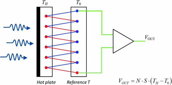
Sketch of a thermopile: output voltage is proportional to the temperature difference (TH − T0); S = Seebeck coefficient; N = number of thermocouples
-
Differential absorbing surfaces (black and white). The idea of estimating solar irradiance as being proportional to a temperature difference between the two surfaces is extended in these sensors by allocating both surfaces exposed to the Sun. One of the surfaces is black (absorbing shortwave and longwave radiation), and the other is white/reflecting/metallic (only absorbing longwave radiation). Usually, several black-and-white areas (in the form of a chessboard or circular pie portions) are combined, as in the examples of Fig. 2. The temperature difference is measured with an electrical resistance thermometer or by a thermopile structure (hot junctions beneath the black surface, cold junctions under white one). With the development of higher-precision instruments, these sensors have been classified as of lower accuracy and used in many cases only for diffuse irradiance measurements. Some examples are: the Callendar pyranometer (1898, Callendar and Fowler 1906), the Angström compensation pyranometer (1919, Coulson 1975), the Eppley model 50 “light bulb” pyranometer (1930), the Yanishevsky pyranometer (1957), and the Eppley model 8-48 (1969) (Stewart et al. 1985; Vignola et al. 2012).
Fig. 2 
Some examples of black-and-white pyranometers: (left) a Yanishevsky pyranometer used for albedo measurement, (right) an Eppley model 8-48 diffuse pyranometer
-
Calorimeter-like sensors. A metal disk or cylindrical vessel (silver, brass) with a blackened absorbing surface, and filled with water or mercury (a liquid medium), is exposed to the Sun in the normal direction. Changes in the temperature of the liquid due to the absorption of radiation can be tracked by a conventional thermometer (a mercury thermometer, a resistance wire) in direct contact with the liquid or the disk, as depicted in Fig. 3. The disk was alternately exposed to sunlight (direct normal irradiance) and then shaded (or rotated) in periods of 2–5 min, in a sequential run. Examples of these types of instruments were the Pouillet’s pyrheliometer (Pouillet 1838), the Abbot silver-disk pyrheliometer (Abbot and Fowle 1908), and the Marvin pyrheliometer (1910, Foote 1919). Abbot and Marvin’s devices used a collimating tube defining the field of view. The difference between temperatures during the shaded and unshaded periods, together with characteristics of the sensor (heat capacity, area, etc.), allowed to estimate the irradiance. At that moment, an improved version of Abbot pyrheliometer (Abbot 1913) was one of the best state-of-the-art accurate instruments for direct solar irradiance and was adopted by the Smithsonian Institution to be the reference instrument to base its irradiance scale (Abbot and Aldrich 1913).
Fig. 3 
(left) Pouillet’s and (right) Abbot’s pyrheliometers, two examples of calorimeter-based sensors of direct solar irradiance
-
Electrical substitution radiometers. Based on the principle of electrical substitution (and/or electrical compensation), first applied by Angström in 1893 (Ångström 1894; Angström 1899), these instruments are self-calibrated and considered as primary absolute radiometers. The principle of substitution assumes that heating produced by the absorption of solar radiation in a black metallic strip (or in a cavity) and heating produced by an electrical current circulating through the strip (or through a wire intimately endorsed to the cavity) are equivalent, as to produce the same temperature rise in a thermopile or resistance thermometer. As voltage and current can be measured with high accuracy, the irradiance is estimated from measurement of electrical power supplied to the sensing element. In the case of Angström electrical compensation pyrheliometer (1893), two strips of black-painted manganin foils are exposed alternatively to sunlight (one shaded, the other unshaded in every run) by means of a reversible shutter at the front of the collimator tube. The shaded strip is electrically heated to reach the same temperature as the exposed strip. In the case of the primary absolute cavity radiometer (PACRAD) developed by Kendall in 1969 (Kendall 1968), the front cavity is alternatively exposed to and shaded from sunlight, while a second twin cavity (compensation cavity) is kept in the dark at ambient temperature. In the closed period, the electrical current heats the front cavity until the same temperature difference with reference to the rear cavity, as in the open period when the front cavity is radiatively heated, is reached. Active- and passive-type absolute cavity radiometers (ACRs) were later developed based on Kendall’s PACRAD and allowed WMO for the definition of the World Radiometric Reference (WRR) in 1979. Both Angström and ACR pyrheliometers are currently the primary reference instruments for the magnitude of solar irradiance in many national radiometric laboratories. Due to the key importance of these sensors, further details are later given in other sections of this chapter.
-
Photoelectric devices. While previous instruments were thermal-type sensors, these are photon-type sensors, mainly based on the property of semiconductor materials and alloys of experiencing electronic transitions and excitations to different energy levels as a consequence of absorption of radiation photons. Thus, this description mainly refers to photovoltaic-type (PV) devices, as photodiodes (PD) and solar cells (SC), and not to photomultiplier tubes (PMT). PMT is really based on the photoelectric effect (the emission of electrons out from the surface of a material being illuminated) and then can be considered as photoemissive detectors. However, a PMT has a very different structure than PV devices and is constructed to detect very low levels of radiation (even photon-count devices) and not for solar irradiance levels. PV-type devices are designed to provide an electrical current (and to produce a difference of potential) proportional to the irradiance absorbed. Although both types of devices have a similar structure (usually based on one or more p–n junctions created by differential doping of the semiconductor), in PD the main focus is put on sensing radiation (linearity, speed, low noise, high sensitivity, etc.), while SC is devoted to converting solar radiation power into electrical power (high efficiency, low series resistance, low thermal coefficients, etc.). For the same reason, PD are prepared for working under low to moderate levels of irradiance (except if a diffuser/attenuator is added), while SC can be used at normal solar irradiance levels and can especially be designed to work under high levels of optical concentration (up to ~2×10⁶ W/m2). However, in both cases, spectral range is limited by the bandgap of the material, and thermal/noise effects reduce the performance of IR sensing devices except if cooled. Some commercial examples are shown later in Sect. 5.
Fig. 4 
(left) Angström strip-type and (right) PMO6, an ACR-type primary reference by PMOD/Davos Instruments, both pyrheliometers based on electrical substitution or compensation principles
-
Photoresistive and photoconductive sensors. Except for some special devices (photoresistances used as penumbra/sunrise/sunset detectors), this type of sensors is not generally used in solar radiation sensing but as IR or thermal detectors. However, it is worth to mention them because of their close relationship with some of the previous instruments. In both cases, radiation received in the sensor promotes an increase in the temperature and, as consequence, in its electrical resistance (photoresistances) or its conductivity (photoconductive devices). A bolometer is a special kind of photoresistance with a high-temperature coefficient of resistance, made of a thin film of metal or semiconductor, and was invented by S. P. Langley in 1880 (Langley 1880; Callendar and Fowler 1906). Photoconductive (PC) sensors are made of semiconductor films and are based on the changes in the conductivity of the material (as a consequence of a change in the population of free electrons in the conduction band) produced by a temperature variation or by absorption of radiation (Palmer and Grant 2010). In the end, a PC device or a bolometer, connected as part of a circuit (see Fig. 5), functions as a resistor whose resistance depends (linearly or exponentially) on the light intensity.
Fig. 5 
Polarization circuits for a bolometer (half-bridge circuit) and for a photoconductive device (PCD). The capacitor is placed to block DC component when using a modulated signal/beam (required for bolometer, optional for PCD). RZ represents the variable resistance of the bolometer or the PCD, while RL is a load resistance, after Palmer and Grant (2010). In both cases, maximum power transfer is obtained when RZ = RL
-
Thermomechanical devices. In these sensors, absorption of solar radiation energy produces some kind of appreciable mechanical perturbation. In the case of bimetallic radiation sensors (as in bimetallic thermometers), a couple of identical size strips of two metals with different expansion coefficient are joined (forming a bimetallic strip) and are connected to a gauge. Heating caused by solar radiation produces a differential thermal expansion on these metals, which can be sensed by the gauge. It is not used in practice for monitoring or recording of solar radiation by its lack of accuracy, and it is valid only for a rough naked-eye estimation of incident radiation. Another type of thermomechanical instrument is the Crookes’ radiometer or light mill (invented 1873) (Crookes 1874), based on the different absorbing properties of black-and-white/metallic surfaces. In this, a set of vanes which are mounted on a spindle inside an airtight glass bulb, containing a partial vacuum, can rotate with a speed proportional to the light intensity. The motion of the vanes is in fact promoted by the movement of gas molecules between both faces of the vanes. Nowadays, it is only used for demonstrative or academic purposes and not as a sensor itself. Modern versions of this instrument have been developed, as a monocolored curved-vane micromotor (Han et al. 2011) and a 100-nm gold light mill (Liu et al. 2010).


Specific details about the practical use of devices and sensing elements above presented are discussed later, in different sections of the chapter. Additionally, there are other IR and thermal sensors not mentioned here because, to our knowledge, they are not used in solar radiation applications, as pyroelectric devices (see, e.g., Putley 1977), phototransistors, and Golay cells (Golay 1947a, b).
2 Calibration and Traceability
Gaining accuracy in the determination of solar irradiance has been of the major concern since the early days of solar radiometry (Fröhlich 1991). The description of the various instruments and physical phenomena applied in this field, given in the previous section, together with the history and evolution of the irradiance scales along the preceding decades (see below), is a demonstration of the huge effort employed by many researchers worldwide along the time in the consecution of this objective.
As in all the scientific areas, every instrument and sensor devoted to estimate a physical magnitude (as solar irradiance) has to be referenced to universally accepted standards, scales, and units. It is the only way the results given by laboratories and researchers in different locations (even in different points of solar system and beyond) can be compared. The reference frame, internationally agreed since 1960, is the International System of Units (SI).
The irradiance of a radiation source is a derived magnitude in SI, defined as the surface density of radiant flux or power (McCluney 1994), the radiant flux per unit area in a specified surface that is incident on, passing through or emerging from a point in the specified surface (considering all directions in the hemispherical solid angle above or below the point in the surface), and has units of Watts per square Meter (W m−2) in SI (see Fig. 6).

Sketch for the definition of the irradiance, after McCluney (1994)
The organism in charge of defining, establishing, reviewing, and maintaining the SI is the Bureau International des Poids and Measures (BIPM, International Bureau of Weights and Measures) through the International Committee for Weights and Measures (CIPM). To guarantee the universal equivalence of measurements, the CIPM signs Mutual Recognition Arrangements (CIPM MRA) with National Metrology Institutes (NMI) and some international organisms, once they demonstrate the correspondence of their measurement standards and the calibration and measurement certificates they issue with the rest of NMI (see BIPM 2018), based on the results of international intercomparisons (called Key Comparisons, KC). Additionally, an NMI can give the responsibility of materializing units and scales, carrying out primary calibrations and the preservation of national standards, for one or some particular magnitudes, to a Designated Institute (DI) in its country.
The outcomes of the CIPM MRA are the Calibration and Measurement Capabilities (CMCs), that have to be individually recognized for every participating institute (NMI or DI), which list the different magnitudes or quantities for which calibration and measurements certificates are recognized by the rest of NMIs.
The current list of magnitudes and scientific areas covered under the possible CMCs (list of services, see KCDB 2018) includes three quantities directly associated to solar radiation, although many others under the branch of photometry and radiometry also apply to detectors used in this field:
-
(a)
Responsivity, solar, power.
-
(b)
Responsivity, solar, irradiance.
-
(c)
Responsivity, solar, spectral, irradiance.
Figure 7 shows these quantities and their current position in the table of recognized magnitudes in the KC—CMC.

Position of the three magnitudes associated to solar radiation in the SI, as given in the list of services of Calibration and Measurement Capabilities (CMC) in the Key Comparison Data Base (KCDB) of the BIPM (see text)
Nevertheless, the current status of these solar radiation magnitudes within the SI is quite new, and solar irradiance scales are in fact pending of a better foundation within SI due to some discrepancies found in the past when compared to SI irradiance scales at NMI laboratories (see Appendix). A short review of the preceding history of solar irradiance scales is convenient at this point.
2.1 Solar Irradiance Scales and Reference Standards
Historically, solar irradiance was mainly considered as a meteorological variable, and thus, its natural place was under the cover of the International Meteorological Organization (IMO), created in 1873, superseded in 1950 by the World Meteorological Organization (WMO). The influence of solar radiation and its possible changes in weather and climate were one of the fields being researched into since the late nineteenth century. A complete review of the history of solar radiometry can be found elsewhere (Fröhlich 1991).
However, radiometry and photometry NMI laboratories used to base their measurement scales and standards in artificial sources (tungsten halogen lamps, UV sources, blackbodies, laser systems, etc.) and/or in related detectors adapted to these sources. Thus, as Sun was a natural (seasonally variable, unpredictable, unstable) source of irradiance, it was not usually considered under the scope of these NMI laboratories. At the same time, measurement capabilities of NMI laboratories were restricted to intensity levels relatively low and, as a consequence, not adapted to solar irradiance. Then, solar irradiance, taken as a physical magnitude, was not under the consideration of the CIPM and not specifically included in the CMCs, as irradiance, as a general quantity, did.
Inevitably, this promoted the independent evolution along the time of primary standards and scales for solar irradiance under the wings of IMO and WMO, out from the scope of CIPM and, in a certain form, out from the SI. Let us say in a parallel way, to express it in a less dramatic form. Figure 8 shows schematically the evolution of these scales and standards.

Evolution of primary reference standards and scales in solar irradiance radiometry. After Finsterle (2015)
As shown, two irradiance scales were defined at the beginning of the twentieth century, almost at the same time: the Ångström scale (1905), based on the Ångström compensation pyrheliometer, and the Smithsonian scale (1913), based on the Abbot and Fowle stirred silver-disk pyrheliometer, already mentioned in Sect. 1. However, several comparisons revealed important differences between both solar irradiance scales (Fröhlich 1973; Latimer 1973). With the objective of getting homogeneous irradiance measurements worldwide, the International Pyrheliometric Scale (IPS-56) was defined in 1956. In 1959, WMO organized the First International Pyrheliometer Comparison (IPC-I) in the Physikalisch Meteorologisches Observatorium Davos (PMOD, Davos, Switzerland). However, this first and the subsequent IPCs did not solve the discrepancies between both scales and neither the new IPS-56 was able to promote a clearer and more stable frame.
At the end of the decade of 1960, a new type of electrical substitution radiometers was developed in the Jet Propulsion Laboratories (JPL), in the framework of the US space race R&D efforts: the absolute cavity radiometers (Haley et al. 1965; Kendall 1968). Due to their better performance, similar instruments were readily developed in a few years, with different denominations: PACRAD, ACR, PMO, CROM, HF, TMI (Geist 1972; Crommelynck 1973; Willson 1973; Brusa and Fröhlich 1975; Hickey et al. 1977). The high accuracy and stability of these new radiometers led to the selection of new reference standards and the definition of a new irradiance scale. Results from the IPC-IV (1975) allowed the settlement of the World Radiometric Reference (WRR), defined as the mean value of 15 absolute radiometers of 9 different models with an estimated accuracy of 0.3% (Fröhlich 1978).
WRR was taken by WMO as the reference primary standard for solar irradiance measurements, and PMOD (Davos) was designed as World Radiation Center (WRC), in charge of maintaining the World Standard Group (WSG) of reference radiometers used to materialize the WRR. Every radiometer of the WSG is a practical realization of the unit of irradiance W m−2. Since then, IPC has been organized every 5 years by WMO/PMOD to disseminate the WRR reference and to validate the stability of the WSG. E.g. IPC-XII was celebrated in 2015.
2.2 Next Steps to Join SI
As any other reference standard in the SI, the WRR has to show long-term stability and has to allow accurate and homogeneous worldwide measurements of its magnitude (the solar irradiance). This way, measurements done at different points of the Earth and in different moments along time have to be comparable and equivalent. For example, only a stable irradiance reference is able to detect subtle changes at a climatic, environmental, and Sun emission level. For weather, environment, or climatic applications, long-term stability can be more important than absolute precision. For solar energy applications, instead, absolute accuracy and small uncertainty can be as important as long-term stability (Finsterle 2015).
WRR can be considered as a primary reference which realizes the unit of solar irradiance, the W m−2, and as such, it defines a scale based on a physical artifact or prototype (as in the past with the unit of mass, the kilogram).
However, according to BIPM principles, the primary standards must be guarded and maintained by NMIs. Then, METAS (NMI in Switzerland) named PMOD as Designated Institute and it signed the CIPM Mutual Recognition Arrangement (CIPM MRA) with BIPM in 2008 (Rüedi and Finsterle 2005). PMOD recognized capabilities include 2 CMCs for solar irradiance (for pyranometers and pyrheliometers) and 4 CMCs for UV.
On the other hand, WMO also signed a CIPM MRA in 2010 (after a working agreement previously signed between WMO and CIPM in 2001), being the second international organism in getting a CIPM MRA. WMO is then equivalent to an NMI and can define its own Designated Institutes to preserve primary standards and to carry out primary calibrations. WMO coincidently chose WRC/PMOD as DI for solar irradiance (2 CMCs) and UV (4 CMCs) within its CIPM MRA. Then, acting as WMO DI, the solar irradiance scale based on WRR is disseminated from PMOD/WRC to standard sensors in WMO regional and national radiometric centers, and to those responsible of BSRN stations, as before, but now until the formal structure of BIPM. IPC could also be used to carry out Key Comparisons between WRR and other standard ACRs of international NMI/DI.
Therefore, the circle is closed in the sense that WRR can be understood as the primary reference in a solar irradiance scale, both through the designation of PMOD by METAS (at Switzerland national scale) and through its designation by WMO (international scope). WRR-based (or any other future alternative) solar irradiance scales are no longer out of the scope of CIPM, and the magnitude of solar irradiance is fully integrated into SI.
However, there is only a little detail to be solved in the near future concerning the practical realization of the solar irradiance scale based on WRR. As a result of several intercomparison carried out between WRR and SI reference irradiance standards (absolute cryogenic radiometers), the WRR has currently no equivalence or compatibility to the SI laboratory irradiance scales implemented by NMIs (Romero et al. 1991, 1995; Finsterle et al. 2008; Fehlmann et al. 2012), and it is temporary out from SI (in terms of traceability). The difference in the determination of irradiance is larger than 0.3% between both scales, and their uncertainty ranges do not overlap this difference. In the Appendix of this chapter, there is a more detailed explanation of this issue.
Despite this transitory affair, the fundamental aspect to highlight here is that, whether a particular solar irradiance scale is based on WRR or another prototype realizing, the unit of W m−2 (that might supersede WRR in the future, as the cryogenic solar absolute radiometer CSAR could do, or perhaps a new, particular realization of the unit by an NMI), the integration of the magnitude “responsivity, solar, irradiance” into SI structure is solved.
2.3 Traceability of Solar Irradiance Detectors
In metrology, calibration of a specimen or device is the comparison of some of its measurands (its properties, characteristics or the output or signal delivered by it) to those of a reference standard of known accuracy (and, therefore, of known uncertainty) under specified working conditions. The calibration allows the determining of the bias, accuracy, and uncertainty of the measurable property of the device under test (DUT) under these conditions.
The traceability refers to an unbroken chain of documented comparisons (calibrations) by which the measurand of the DUT can be related to that of a national standard maintained by an NMI. Every calibration step performed between the national standard and the DUT, by means of intermediate standards in a hierarchical sequence (if any), contributes to (increases) the final measurement uncertainty. Then, less the intermediate calibration steps, (ideally) less the final uncertainty.
Figure 9 shows a sketch of the traceability chain for the different instruments used in a solar irradiance scale. The set at the bottom of this structure (the ultimate recipients of the work done in upper stages) are the working standards and field instruments which are used in (industry and laboratory) testing, in the monitoring of solar plants of different nature, and of weather and BSRN stations. As higher the accuracy and lower the uncertainty required for these applications, as stronger the requirements for the calibration procedures, for the metrological level of measuring instrumentation and for the quality of the standard sensors.

Traceability chain for the calibration of solar sensors, from SI downwards. Yellow boxes refer to absolute radiometers. Blue brackets stand for SI units implemented in every branch. Some ISO and IEC Standards with calibration methods are indicated in red, although several alternative procedures exist
In this sense, some values of reference for these requirements are to be given. For example, the Global Climate Observing System (GCOS) points out the importance of a continuous recording of solar radiation through the BSRN grid (BSRN 2018) and sets a limit of 1 W/m2 for absolute accuracy and 0.3 W/m2 per decade in terms of stability (GCOS 2011, 2016). Requirements pointed out by the National Institute of Standards and Technology (NIST) for future space radiometers are even more demanding: Spectral radiation reflected by Earth surface needs a precision of a 0.2%, spectral solar radiance of 0.1%, and TSI up to 0.01% (Murdock and Pollock 1998; Pollock et al. 2000).
Finally, the accuracy of sensing devices for monitoring of solar PV plants is regulated by IEC 61724-1 Standard (IEC 2017). IEC 61724-1 classifies monitoring systems in three levels of complexity and required accuracy: Class A (high accuracy), Class B (medium accuracy), and Class C (basic accuracy). Class A is recommended for large PV systems, while Class C is recommended for small-size installations. Class A systems require the on-field measurement of several irradiance components (see Table 1), while Class B can either measure or estimate the magnitudes from meteorological stations or satellite data. All the classes must measure these quantities with a resolution ≤1 W m−2.
Returning back to Fig. 9, it is interesting to remark some details. Procedures for calibration of reference pyrheliometers, pyranometers, and solar cells are described in different international standards (ISO, IEC, ASTM, etc.) and in the literature. According to ISO Standards, calibrations of pyrheliometer and pyranometer reference standards are obtained through comparison against a cavity radiometer, traceable to WRR, usually participating in the IPCs. Details about different calibration procedures are given later.
The position of WRR in Fig. 9, as well as that of other standards (silicon trap standards, standard lamps), is below the main SI box to represent they are realizing derived units instead of fundamental ones. Several boxes are especially highlighted (in yellow) to indicate the position of cavity radiometers. Absolute cryogenic radiometers (L-ACR) are used at NMI laboratories to realize the fundamental unit of candela (luminous intensity) and derived units (lumen, lux). These are the kind of instruments WRR has been compared to in the WRR/SI comparisons already mentioned. As explained, WRR/WSG is the practical realization of the unit of W m−2. To date, all the absolute cavity radiometers of terrestrial use (T-ACR), of active or passive type, mainly used by WMO national and regional centers and BSRN stations, or used by solar sensor manufacturers or by specialized calibration laboratories, are characterized by comparison against WRR during the IPCs. Special calibration procedures are applied for absolute cavity radiometers for use in space (S-ACR), against WRR or against SI laboratory-scale L-ACRs. Finally, the CSAR is introduced in this sketch occupying a position near WRR because of its potential inclusion in or substitution of WRR in the future.
The hierarchical level of pyrheliometers and pyranometers in the irradiance scale depends on the quality and metrological characteristics of the sensor. Two main classifications are recognized in this field: the ISO 9060 Standard (ISO 1990a) and the CIMO/WMO Guide (CIMO 2017). ISO 9060, for example, distinguishes (in its 1997 edition) three classes both for pyranometers and pyrheliometers: secondary standard, first class, and second class. This classification is made attending to different performance and physical aspects: response time, zero offsets, resolution, non-stability, temperature response, nonlinearity with irradiance, spectral sensitivity, tilt response, and directional response for beam radiation (only in the case of pyranometers). All these magnitudes of influence and technical aspects are later discussed (Sects. 3 and 4), and specific ranges for instrument classification are collected (see Tables 4 and 5). However, ISO 9060 is suffering a revision and its new edition (foreseen for fall of 2018) introduces some changes (see below).
Reference solar cells are special kind of irradiance sensors whose inclusion, in this context, makes sense for (a) the calibration of secondary cells and photodiode-based sensors, and (b) its role in the monitoring of PV plants (of matching technologies), though their spectral sensitivity ranges are narrower than those of thermopile-based instruments. This is also referred to in IEC 61724-1 Standard. Their primary calibration can be obtained by several methods and traceability chains, as indicated in Fig. 9, many of them covered in the IEC 60904-4 Standard (IEC 2009). One of these methods is based on the use of absolute cavity radiometers, traceable to WRR, as done with pyrheliometers and pyranometers (Emery et al. 1988; Osterwald et al. 1990). Secondary calibration of solar cells by comparison against reference solar cell is covered, for example, by the IEC 60904-2 Standard (IEC 2015).
3 Measurement of Direct Normal Irradiance
In a clear day, up to ~90% of irradiance reaching a surface on the ground, with adequate orientation and tilt, can come from the Sun disk and aureole/circumsolar regions of the sky. These, as a whole, form the direct normal irradiance (DNI). The sun disk subtends an angle of ~0.535° (McCluney 1994) to an observer on the Earth, almost the same angle as the Moon. This is why, during a solar eclipse, the Moon perfectly covers the Sun although its mean orbit is about 385,000 km (0.00257 AU), much closer to Earth than the Sun.
However, the amount and the character of the circumsolar radiation vary widely with geographic location, climate, season, time of day, and the observing wavelength (Buie and Monger 2004). There is also some uncertainty in the edge limit of the solar disk (Blanc et al. 2014) and the solid angle that must be considered to account for DNI, although it has lately been determined as of a radial displacement or half angle of 4.65 mrad or 0.266° (Puliaev et al. 2000). The profile of the radiance, or of the radiation intensity, decreases from the center of the solar disk to the edges, and circumsolar radiation influence extends up to about ±2.5° with a linear-like dependence in a log–log plot (see Fig. 10). The relative intensity of the circumsolar region to that of the sun disk is obviously also dependent on the atmospheric scattering and contents on particles, aerosols, etc.

Out from this narrow solid angle subtended by ±2.5°, the rest of the skydome emits diffuse irradiance over the receptor. This is, therefore, the reference aperture for the opening angle θO used to define the field of view (FOV) of an instrument designed to measure DNI over the Earth’s surface, as a pyrheliometer. These apertures are usually arranged inside a pyrheliometer in front of the detector, concentric around a common optical axis with rotational symmetry, in the form of a collimating tube, and thus defining a view-limiting geometry as that shown in Fig. 11. WMO CIMO currently recommends values of θO = 2.5° and θS = 1° (CIMO 2017), although there are other accepted criteria with wider ranges (e.g., ASTM E1125-99). As an example, Table 2 includes the angles and dimensions for some cavity- and common thermopile-based pyrheliometers.

View-limiting geometry of an instrument measuring DNI. Opening θO, slope θS and limit θL angles are dependent on the size or radius r of the sensor aperture stop, that of the front aperture R (field stop) and the distance L between them
Far from the atmosphere limits, solar irradiance is only direct, and there are no diffuse components (interstellar space is in practice a no dispersing medium, despite the existing small amounts of gas, dust, and particles). Irradiance on the top of the outer atmosphere varies around ~7% along the year (between aphelion and perihelion) only because of the movement of the Earth along its orbit around the Sun, and the small eccentricity of this orbit. This does not affect the value of the solar constant, which is determined for a fixed distance of 1AU and whose small periodic variations (of the order of 0.1%) have no relationship with this orbital displacement but with the apparition of dark spots and faculae in the Sun’s surface. Some additional details on the measurement of total solar irradiance (TSI) in space are described in Appendix.
3.1 Solar Absolute Cavity Radiometers (ACR)
As introduced before, pyrheliometers on the top metrology level for on-ground measurement of DNI are absolute cavity radiometers (ACR) working under the principle of electrical substitution. These are open air, unencumbered sensors (neither windows nor domes are usually used), so they are sensitive to both SW and LW radiation. Solar ACRs are constructed having two twin cavities, one intermittently exposed to the sunlight and a second (reference or compensating) cavity operating at an ambient temperature in the dark. Figure 12 shows a diagram of one of these cavity radiometers. The realization of the unit of irradiance W m−2 in one ACR is based on the materialization of two other magnitudes: area (m2) and power (W). While the area is obtained by the accurate measurement of the diameter of the precision aperture at the entrance of the cavity, the power is calculated in an indirect way by measuring the temperature (or the heat flux) reached in the cavity when it is illuminated by sunlight and when it is heated by an electrical current. It is then based on the assumption of the equivalence between heat produced radiatively and heat produced electrically (Joule effect). An extremely careful design of the cavity, the heating electrical circuit, the temperature sensors, and their measurement circuits try to ensure that this equivalence principle holds.

Cross section of an absolute cavity radiometer, with a double cavity arrangement. Only the frontal aperture (sunlight entering by the shutter side) is illuminated while rear (compensating) cavity is in the dark and acts as reference cavity working at ambient temperature. After Fang et al. (2014)
Although with differences in operation modes among different instruments (mainly between passive and active types), they operate in two steps, phases, or stages: the open phase and the closed phase, in reference to the position of the frontal shutter. During the open phase, DNI sunlight enters through the view-limiting aperture and heats the cavity, with a radiant power of up to ~45 mW (for a typical aperture area of 0.5 cm2). During the closed phase, a small current of tens of milliamps circulates through a heating circuit whose wires are intimately adhered to the cavity by its rear side. The voltage/current injected during the closed phase is regulated until the temperature difference between both cavities (or the heat flux toward the heat sink) is the same as in the open phase. Therefore, equal heat flux (equal temperature difference) must imply equality between electrical power (P = V × I) and radiant power.
In practice, real absolute cavities are affected by slight deviations from the ideal behavior, contributed by several optical, radiative, thermal, and electrical effects, some of them grouped under the term non-equivalence. Therefore, solar ACRs are to be characterized, by two different ways: (a) through the calibration and assessment of every of the magnitudes of influence in the equation governing its operation, or (b) by direct comparison against WSG/WRR (or any future standard reference embodying the unit W m−2 and realizing a scale of solar irradiance). However, and due to the relative ease of the characterization, by comparison, WMO suggests the second way for the cavity instruments giving support to WMO national and regional centers and to BSRN stations. Every radiometer measuring solar irradiance must be traceable to WRR, according to WMO guidelines. Transference is performed in the International Pyrheliometer Comparison (IPC) celebrated in the PMOD/WRC every 5 years. After the IPC, a deviation factor with respect to WRR (and the corresponding 1σ uncertainty) is calculated for every participating instrument. This deviation factor must be included after in the calibrations performed by every particular ACR and the uncertainty included in its final uncertainty budget. Details about the IPC operation, participants, data acquisition and validation, results for instruments, and the procedures applied for calculating the reference irradiance based on the measurements from the WSG, can be obtained from the IPC reports (Finsterle 2011, 2016).
3.2 Field Pyrheliometers
Pyrheliometers for on-field operation, solar (thermal, PV) power plants, and weather/BSRN network stations, while accomplishing for the view-limiting geometry already described, are much simpler than cavity radiometers. Correspondingly, they are less accurate. Classic design pyrheliometers, still in operation and in the market, are based on a thermopile as radiation sensing element, being therefore analog, passive instruments not requiring a power supply to operate. Typical sensibility, depending on thermopile configuration, is between 5 and 20 μV/W m−2. The internal structure of these instruments is depicted in Fig. 13, also showing the placement of sensors at the end of the collimating tube.

Internal structure of a (secondary standard, first class) pyrheliometer. After Kipp and Zonen CHP1 manual
Some examples of pyrheliometers commercially available in the market are collected in Fig. 14. Almost all of these instruments have several common features: a long cylindrical-shaped architecture, associated to a sunlight collimating tube; a metallic body (aluminum, stainless steel) for long-term durability; an alignment sight, sunspot indicator, or pointing aid; a frontal window to protect the sensor and create a watertight enclosure; and, on the rear side, an external connector for output signals and a small removable plastic tube or cartridge with desiccant. As they use frontal windows, LW radiation is filtered and only SW is measured. They are usually fixed to the supporting structure (in a Sun tracker, see below) by clamps or braces wrap around the cylindrical body.

Examples of some commercial type (secondary standard, first class) pyrheliometers: a sNIP by Eppley, b DR01 by Hukseflux, c CHP1 by Kipp and Zonen, d MS-56 by EKO
Modern versions of these instruments, recently introduced in the market, incorporate one or some of the following features: a faster response, amplified voltage signal (e.g., 1 mV/W m−2), output in 4–20 mA current loop, digital outputs (e.g., Modbus RS485), microprocessor, heating elements, tilt angle sensor, temperature sensor, and temperature compensation circuit. While the T sensor is still an analog signal, the rest of the characteristics require to feed the pyrheliometer with an external power supply. It is then a change in the philosophy of sensing solar radiation: simple-passive-analog devices versus complex-active-digital ones. This change does not necessarily imply an improvement in accuracy or uncertainty, neither in the internal structure nor in the external shape. It is more an extension of equivalent solutions applied for other sensors to attend the demand of large, extended, and accurate monitoring systems in industry and power plants. A similar technical development is being experienced in pyranometers’ market.
On the other hand, due to the need of continuously pointing to the Sun’s disk, pyrheliometers require the use of an automated/motorized platform which follows the Sun trajectory in the sky along the day and along the year. These platforms are mounted in two-axis Sun trackers or sun trackers, which use motors and gear trains driven by microprocessors and location-, date- and time-based algorithms to calculate the position of the Sun. These systems are preferred to trackers only based on sensors, although a pointing sensor is usually added to the tracker operative in order to check the accuracy of the algorithm, the performance of the tracker and to introduce on-the-fly corrections. Pointing errors up to 0.1° can be admissible for sensing DNI (CIMO 2017) while other applications could demand better accuracy. Sun trackers of diverse designs are also used to move solar panels in PV power plants, to carry parabolic troughs, Fresnel reflectors, lenses, or the mirrors of a heliostat. Figure 15 shows an example of sun trackers used for solar radiation measurements. The cost of a two-axis tracker is considerably higher than that of a pyrheliometer, even a secondary standard, by the way.

Examples of two-axis sun trackers used for solar radiation instruments, by Kipp Zonen (left) and Hukseflux (right)
Finally, it is worth to mention a new type of sensor for assessing circumsolar radiation and to account for its influence in the calibration and in the DNI measurements done with different pyrheliometers. It was developed by Black Photon and successfully used during last IPC-XII (2015), to the point of being used as an additional criterion for acceptance and validation of data. Figure 16 shows an image of these new sensors, BPI-CSR460. The calculation of circumsolar radiation for a given solid angle was obtained by the difference between output signals of partially shaded and unshaded electronic sensors. It was used as an indication of varying and unstable irradiance conditions (Finsterle 2016). It had also been tested previously for evaluating the influence of circumsolar variations on concentrating solar collectors (Wilbert et al. 2013).

Measurement of circumsolar radiation from the difference between DNI signal of partially shaded and unshaded sensors during IPC-XII in Davos, performed by Black Photon Instruments
3.3 Classification of Pyrheliometers
The performance of pyrheliometers is dependent both on technical capabilities (and/or limitations) and on external working influences (of environmental nature). The difference in the quality and accuracy of different instruments, excluding primary absolute radiometers, made necessary the classification of pyrheliometers to state and to compare their metrological level. Although quite similar in some aspects, the classifications of pyrheliometers according to both WMO CIMO Guide and ISO 9060 Standard (ISO 1990a) specifications are collected in Table 4. Two categories are recognized by WMO, while three are distinguished by ISO in the case of pyrheliometers, and both establish three (near identical) categories for pyranometers. Better class implies higher metrological level and instrument quality. The characteristics included and categorized in Table 4 (and similarly in Table 5 for pyranometers) are mainly related to the behavior of thermopiles as sensors and not all of these characteristics are directly portable to another kind of instrument. To our knowledge, the new version of the ISO 9060 Standard seems to keep near identical the requirements for each class included in Table 4. The name of the categories changes to Classes A, B, and C (substituting respectively to secondary standard and first a second class), and a new AA class, of higher requirements, is introduced in the standard, although it seems to be only applied to standard reference instruments (as primary ones). Specific details about other minor changes are to be confirmed in this new edition.
The motivation of these classifications is, in the end, to define which kind of sensor is able to guarantee which level of confidence in the measurement of solar irradiance without the need of measuring additional working parameters (e.g., sensor temperature and ambient temperature). Classifications were conceived having in mind classic analog-passive type of solar sensors. A linear device for DNI or GHI irradiances, and independent of all of the rest of influences, would be the ideal sensor as it avoids performing corrections in the recorded values. Table 3 shows the values reflected by CIMO Guide of achievable uncertainty both for pyrheliometers and pyranometers. Therefore, according to the needs of the accuracy of a particular application (and according to the affordable budget), a given quality of the sensor has to be chosen.
Calibration of pyrheliometers is always performed under natural sunlight by comparison against a standard pyrheliometer, with equal or higher metrological level (equal or better class), and with a known sensibility (μV/W m−2) traceable to WRR. ISO 9059 Standard (ISO 1990b) describes the procedure for calibration, by comparison, valid ranges for minimum irradiance and maximum turbidity, and an indication of uncertainty determination. Usually, calibration during clear and stable days is recommendable and this limits the availability of acceptable days. Different view-limiting geometries between DUT and standard, as well as different time constants and temperature coefficients, can result in calibration errors. Characteristics included in Table 4, common with some of Table 5, are indicative of the relative influence of these parameters for different classes.
Response time of thermopiles is dependent on its size, number of thermojunctions, and the thermal capacity of the structure. Under varying irradiance conditions, the thermopile changes the output voltage following an exponential function with a given time constant. The 95% level is referred to the final value the sensor output would reach under a stable irradiance condition after the change.
With reference to “zero offset,” there are several thermal effects that can be analyzed. On the one hand, the term can be associated with the signal measured on the sensor for a null irradiance condition. Although it should ideally be zero, a thermopile-based radiometer can show a nonzero output value or even a negative one, depending on the amount and the direction of the thermal flux across the thermopile and the temperatures on both sides (at the end, a thermopile can be assimilated to a thermal flux meter). This effect has been extensively analyzed in the case of pyranometers and much less for pyrheliometers, because of the lower impact in the latter (see paragraph 4). On the other hand, “zero offset” refers, in the case of Table 4, to the possible change on the output of the pyrheliometer due to a slow change on the ambient temperature (5 K/h) under constant irradiance (sometimes referred to as zero offset type B). Again, it should ideally be zero because the output of the thermopile should be independent of these slow changes. In the end, both effects have a thermal origin and are intimately related one to each other, but the first one is referred to null irradiance while the second is determined under illumination.
Similarly, there is a characteristic related to a thermal coefficient of the output (‘Temperature response’). In this case, the sensitivity of the sensor is obtained indoors after stabilization of output signal under constant irradiance, but with a wide temperature range covering the normal operation of field pyrheliometers (50 K), usually in steps of 10 K. The resulting data points can be fitted to a curve or straight line to carry out corrections on temperature variations if required.
The rest of the parameters listed in Table 4 are easily understood and will not require further analysis or discussion. Tilt response is of importance for an instrument subjected to a shift in orientation and slope when arranged in a sun tracker. The more sophisticated test required for pyrheliometer classification refers to optical characteristics (absorptance of the sensor and transmittance of frontal windows), limited to the range of shortwave radiation, and which can only be carried out by specialized laboratories. A number of other magnitudes of influence have also been investigated (Thacher et al. 2000).
4 Measurement of Global Irradiance on Horizontal and Tilted Surfaces
Global irradiance is a wider term associated with radiation received in all the directions of space. A round-shaped sensor (a sensing ball) could potentially measure radiation in a solid angle of 4π, while sensors with flat surfaces can receive hemispherical irradiance in a 2π solid angle. When applied to solar sensors, global irradiance stands for radiation composed of BHI (sun disk and circumsolar radiation), diffuse DIF sky radiation, and even reflected (ground, albedo) radiation.
In practice, sensors commonly used to measure solar global irradiance have flat surfaces (thermopiles and thermal flux sensors, solar cells, photodiodes, etc.) and therefore are able to measure hemispherical irradiance. The most extended device for global irradiance measurements is a pyranometer. A pyranometer is a thermopile-based instrument, covered by one or two hemispherical glass domes, and therefore able to measure SW radiation in a 2π solid angle. Except for the different field of view (FOV), the working principle is therefore equal to a pyrheliometer. When placed in a horizontal position, it measures GHI, only composed of direct horizontal irradiance DHI and DIF sky radiation. Pyranometers can also be placed on inclined surfaces, e.g., to measure plane of array (POA) irradiance parallel to a photovoltaic array, or can be placed downwards, in inverted orientation, to only measure ground reflected global radiation (such instruments are called albedometers if they are combined with a horizontal pyranometer). Being placed horizontal, they can also be partially shaded or screened to avoid DNI contribution and thus exclusively measuring diffuse horizontal irradiance (DIF). Although the usual sensing element of a pyranometer is a thermopile, there also exist some models of pyranometers based on solar cells and photodiodes, at the expense of measuring limited spectral ranges of solar irradiance.
Figure 17 shows some examples of commercially available pyranometers of classical design (passive, analog type), while Fig. 18 includes a cross section of these instruments. The sensing thermopile is intimately bonded to a ceramic disk painted black or a plate with an anodized surface, with round shape, and covered by the glass domes. The main body or housing is usually made of aluminum, with three levelling feet for tilt adjustment and a bubble level as an aid for getting the horizontal position, an external connector and a removable cartridge with desiccant. They also incorporate a white sun shield (plastic, metal) in the form of a truncated cone. Some models have a temperature sensor inside (Pt100, thermistor) available through the external connector. Many manufacturers also offer as an option a ventilated unit (fan based) and even an external heating element that can be added to the pyranometers body to avoid or reduce effects of dust, dew, frost, snow, ice, etc., that affect the performance of the instrument and the availability of valid data.

Examples of commercial type standard pyranometers (secondary standard): a GPP and PSP (behind) by Eppley, b SR20 by Hukseflux, c CMP22 by Kipp and Zonen, d MS-802 by EKO. New and improved versions are shown in Fig. 19

Cross section of a double dome pyranometer. After Kipp Zonen CMP22 manual
However, as in the case of pyrheliometers, modern versions of pyranometers can offer many other features for adapting to requirements of International Standards and monitoring networks: heating and ventilating elements already embodied in the pyranometer structure, microprocessor control, analog and digital outputs, amplified voltage and current loop outputs, compensating temperature circuit, lower offsets, and temperature and tilt angle sensors. Another of the most interesting improvements refers to the sensing element: reduced in size thermopile placed on a cavity and covered by a quartz diffuser results in a much faster and sensitive device. Some examples of modern design pyranometers are shown in Fig. 19. Again, there is a shift from passive-analog instruments to active-digital ones.

Examples of new generation of thermopile pyranometers, with improved features (see text). a SR30-D1 by Hukseflux; b MS-80 by EKO; c ER08-SE by Middleton Solar; d SP-510 by Apogee Instruments
The characteristics and classification of pyranometers, according to current ISO 9060 and WMO CIMO Guide, are summarized in Table 5. Remember that the classification for a particular characteristic is conceived as an acceptance criterion of accomplishment of the indicated range. Many of the working operational issues already commented for pyrheliometers are common to pyranometers. In general, requirements are more restrictive for pyrheliometers than for pyranometers for a given class. Due to their 2π FOV and the short distance between domes and thermopile, pyrheliometers are prone to experience larger influences originated by a tilt angle, orientation, directional response (not applicable to pyrheliometers), and zero irradiance offsets.
Zero offsets are separate in two different contributions: the zero offset type A, caused by the longwave radiation emitted inside and outer the instrument and by the different temperatures of thermopile and domes; and the zero offset type B, the possible deviation in the output produced by drifts in ambient temperature.
In particular, zero offset type A in pyranometers have been the subject of dedicated research efforts in the literature (Reda and Myers 1999; Bush et al. 2000; Haeffelin et al. 2001; Philipona 2002; Hernandez et al. 2015). As they are made of different materials, have different thermal capacity, and are in contact with different parts of the radiometer, there are differences in operating temperatures of the black disk, the inner dome, and the external one. Temperature differences promote radiative transfer among these components (due to their different emissivities), and between outer dome and atmosphere or sky (sky can have effective temperatures up to 50 °C cooler in a clear day). This transfer leads to the apparition of a small negative signal which reduces to the output signal of the thermopile. As a result, the true irradiance can be underestimated. However, although it is identified as a source of error in irradiance measurements, these thermal offsets are still not well accounted for, and no clear methodologies have been defined for their assessment. There are also discrepancies among the differences between nighttime and daytime offsets, and between the offsets obtained when measuring global or diffuse irradiance.
On the other hand, with reference to Table 5, it is important to remark that ISO 9060 Standard is being currently under revision (2018) and that new edition includes some noticeable changes with respect to the previous one, especially in the case of pyranometers (Hukseflux 2018). The instrument is to be classified under accuracy classes now labeled as A, B, and C. In the case of pyranometers, Class A devices require the individual testing (and reporting) of temperature response and directional response for every instrument. There is also an extension of every class for “spectrally flat” devices, recommended for POA, diffuse, albedo, and reflected solar measurements. This “spectrally flat” category will apply to instruments not installed in horizontal and exposed to spectral distributions different than that of GHI. Any case, it is necessary to wait until the issue of the new edition to better know all the changes.
With respect to calibration of pyranometers, there are several methods reported in the literature and in International Standards, such as ISO 9847 (ISO 1992) and ISO 9846 (ISO 1993). CIMO Guide also briefly describes some of the most important procedures, including those of ISO 9847. These can be summarized as follows:
-
(A)
Outdoor methods:
-
Comparison of a DUT against a standard pyrheliometer (DNI) and a calibrated pyranometer (diffuse sky irradiance).
-
Comparison of a DUT against a standard pyrheliometer (DNI) by using a removable shading disk for pyranometer (sun and shade method).
-
Comparison of two DUT against a standard pyrheliometer (DNI) by alternatively measuring GHI and DIF with every pyranometer.
-
Comparison of a DUT against a standard pyranometer, even under cloudy and partly cloudy conditions.
-
Comparison of a DUT against a standard pyrheliometer (DNI) by using a collimating tube in the pyranometer.
-
-
(B)
Indoor methods:
-
Comparison of a DUT against a similar pyranometer (previously calibrated outdoors) on an optical bench with an artificial source. This can be carried out at normal incidence or at another angle of incidence.
-
Comparison of a DUT against a similar pyranometer (previously calibrated outdoors) inside an integrating chamber simulating diffuse sky radiation.
-
Finally, it is important to include in this paragraph another two families of sensors used in many applications for measuring of global irradiance (mainly for GHI and POA). These are photoelectric-based devices: solar cells and photodiodes, which are encapsulated or embedded in suitable structures and cable connections as to guarantee long-term stability and performance, and to make easy their direct installation and use on the field. Figure 20 shows some examples of photodiode-based pyranometers, while Fig. 21 includes various types of reference solar cells used in PV power plants and smaller PV systems.

Examples of Si photodiode-based pyranometers: a SP Lite2 by Kipp and Zonen; b Apogee SP-212; c a LI-200R photometric sensor by LI-COR, detached from removable base; d ML-01 Si-Pyranometer by EKO

Examples of commercial reference solar cells used as irradiance sensors: a Si sensor by Mencke and Tegtmeyer; b Sunny Boy sensor by SMA; c Temperature compensated MET solar cell by ATERSA; d same idea in the ISET sensor by IKS Photovoltaik; e Fraunhofer ISE’s outdoor reference solar cell; f Fronius irradiation sensor
While at a lower cost than pyranometers, both kinds of devices measure irradiance only in a limited range of solar spectral distribution (e.g., silicon between 300 and 1150 nm) and therefore are subject to some spectral errors in different moments of the day and along the seasons. Corrections for temperature and spectral sensitivity can improve the measurement results. However, they have a very fast response to varying irradiance. As a whole, they can be an adequate solution for monitoring PV plants of the same or equivalent technology, or for applications only requiring accuracies equivalent to first class or good quality in Table 5.
5 Measuring Diffuse Irradiance
For some applications, ad hoc assessment of diffuse (DIF) irradiance can be advisable or mandatory. Classical solutions for measuring diffuse irradiance are based on the same type of sensors used for measuring global irradiance, mainly thermopile pyranometers. But we can classify approaches usually applied in two categories:
-
1)
By computing the difference between GHI and DNI. The basic idea is quite simple: After simultaneous measurement of global horizontal (GHI) and direct normal (DNI) irradiances with a horizontal pyranometer and a pyrheliometer, the DIF can be computed by the known relation:
$${\rm{GHI}} = {\rm{DNI}} \cdot \cos {\theta _{Sun}} + {\rm{DHI}}\quad \quad \to \quad \quad {\rm{DHI}} = {\rm{GHI}} - {\rm{DNI}} \cdot \cos {\theta _{Sun}}$$The resulting uncertainty of this computation will be affected for those of the individual measurement of global and direct components, having in mind all the characteristic parameters of influence already commented in previous sections. On the other hand, this approach would not be admissible for Class A (high accuracy) monitoring systems for PV power plants regulated by IEC 61724-1 Standard, because direct measurement of DIF is required.
-
2)
Applying a static or sun-tracking shadow over a horizontal pyranometer. The easier way of evaluating DIF is to block up or occlude the DNI on a pyranometer measuring GHI by using an opaque shading gadget. More accurate results are obtained when the solid angle subtended by the shading device over the pyranometer sensing element equals that of the pyrheliometer measuring DNI. Otherwise, some corrections should be applied to account for the difference in the FOV. Figure 22 shows the traditional solutions developed to shadow horizontal pyranometers for measuring DIF. These comprise, first, static elements as shadow rings or shadow bands tilted in such a way that is coincident with the Sun’s path (ecliptic) along the day. As the apparent motion of the Sun varies between maximum trajectories occurring at solstices, it is necessary to correct the position of the shadow element from time to time along the year. Besides, the shadow band or shadow ring is screening the sensor from a portion of the diffuse radiation coming in from the sky, and corrections have to be applied (Batlles et al. 1995; CIMO 2017). The second type of shadowing solution is based on two-axis tracking systems to which light articulated arms or structures with shadow balls or shadow disks are arranged. The tracking system continuously displaces the disk’s or ball’s arm to follow Sun’s position at all times, and therefore, the pyranometer is permanently shadowed from DNI. Additionally, zero irradiance signals can become an important source of errors and methods to minimize its influence are to be introduced (Hegner et al. 1998).

Examples of traditional arrangements for measuring diffuse irradiance based on standard pyranometers: a, b shadow band and shadow ring manually adjusted; c, d shadow balls and shadow disks arranged in two-axis sun trackers
An alternative to such conventional arrangements is a motorized rotating shadow band which intermittently occludes from direct irradiance a photodiode-based pyranometer (see examples of Fig. 23). The arm is moved around the sensor head which measures GHI when unshaded and measures DIF when shaded. Most of the systems available in the market work with a continuous rotation (constant angular velocity), while a few move the band back and forth at periodic intervals. These instruments can also compute the DNI by using the recorded values of GHI and DIF. Operational and performance details can be found elsewhere (Wilbert et al. 2015, 2016).

Two equivalent concepts of rotating shadow band based on a fast response Si photodiode as irradiance sensor
Another alternative to measure DIF and GHI with a single instrument and without any moveable components is the SPN1 developed by Delta-T Devices (see Fig. 24). The instrument is based in a set of seven fast thermopile detectors, distributed in the same plane in a hexagonal pattern, and covered by diffuser disks. A specially designed shadow mask, created from a hemispherical surface, is placed over the devices and under a glass dome. With this mask, there is always at least one sensor shaded and at least one sensor unshaded for any position of the Sun in the sky. Both sensors (rotating shadow band and masked shadow) have demonstrated a similar accuracy for measuring GHI, but measurements of DIF with SPN1 have higher errors than those obtained with rotating shadow band.

A new concept for the measurement of global and diffuse irradiance with a shadow mask and without any moveable parts: SPN1 pyranometer by Delta-T. There is always at least one shaded and one unshaded sensor
6 Other Broadband Solar Sensors: Total and Longwave Radiation
Preceding instruments are devoted to measure and characterize SW irradiance (λ from 0.3 to 3 µm), but, as commented in the first chapter, there is a great interest in the determination of LW irradiance (λ from 3 to 100 µm) that has a terrestrial and atmospheric origin (thermal radiation). The measurement of these components at the ground level is very important to compare them with those being measured in the outer atmosphere by radiometers in spacecrafts.
Two kinds of instruments are to be commented to this respect: pyrradiometers and pyrgeometers. Put together in pairs to measure downward and upward radiation components, or in association with a couple of pyranometers measuring GHI and albedo in the SW range, they conform a set of four-component net radiometers which are the basis for evaluating total radiation budget at terrestrial level. Figure 25 includes some examples of these four-component net radiometers available commercially.

Examples of four-component net (pyr)radiometers: a NR01 net radiometer by Hukseflux; b Apogee SN-500 net radiometer; c CNR4 net radiometer by Kipp and Zonen; d MR-60 net radiometer by EKO
A pyrradiometer is a thermopile-based instrument, able to measure total radiation, including SW and LW, in a hemispherical 2π solid angle. They must have a constant sensitivity in the entire spectral range SW + LW (λ from 0.3 to 100 µ). Computing the difference of two of these instruments arranged for measuring downwards and upwards, the net radiation can be obtained.
A pyrgeometer is designed for measuring LW radiation, also sensing thermal radiation with a thermopile. In most cases, the shorter λ range is eliminated by means of high- or long-pass filters (e.g., domes or disks made of silicon with additional solar blind filters, or directly deposited over the thermopile sensor) to make them opaque to SW while keeping constant transmittance in the LW range. In some cases, when SW range is not fully filtered by the instrument optics, they have to be used only at night.
When measuring with these instruments having filters added, it is important to note that the own domes, covers, and filters emit radiation themselves because of their operating temperature (blackbody radiation) and temperature sensors have to be included to account for this contribution. Internal heating elements to keep the instrument above dew point and to avoid water vapor condensation is also important, because water filters LW radiation and can alter the measurement results. Additional sources of error, operational characteristics, and classification of instruments can be found in the WMO CIMO Guide (CIMO 2017) and are not included here for completion.
7 Solar Spectral Measurements
The knowledge of the spectral distribution of solar radiation (as well as of other artificial light sources) is of major interest for many scientifical areas: biology, agriculture, human health, weather, air quality, etc. The measurement of spectral distribution is performed by instruments named spectroradiometers. It is again one of the magnitudes of basic knowledge to assess several essential climate variables under WMO GCOS. The specific spectral range every technical area is interested in, the intensity of the irradiance received by a particular object or substance, and the technical capabilities of different types of sensors, have resulted in a wide variety of spectroradiometers available in the market. However, many of these instruments are conceived for its use in laboratory environments, for working under low-intensity light levels, with indirect or reflected light beams, or in relatively narrow spectral ranges, and therefore can become not suitable for solar applications.
The basic element in a spectroradiometer is a spectrally dispersive device, like a prism, a ruled diffraction grating or a holographic diffraction grating. Chromatic dispersion of light is a natural phenomenon that people are familiar with, because the formation of the rainbow is due to the same physical process (light scattered by raindrops). Rainbow-like dispersive effects in the surface of a CD or a DVD, or in the border of a curved glass lens, are also result of the same phenomenon.
The grating in a spectroradiometer separates (diffracts) the incoming white (broadband) light into its component wavelengths λ in a continuous spatial distribution, because every wavelength interval Δλ is progressively dispersed from the surface of the grating in sequential adjacent angle Δθ. Diffraction gratings can be manufactured to work by transmission or by reflection, but reflection is the usual election for optical instruments. Reflection gratings are manufactured by “sculping” a set of closely and uniformly spaced parallel grooves, in a mirror coating with a flat glass substrate. The angular width of the scattered light, the spectral resolution, and the spectral range in which the grating disperses the light are design parameters dependent on the physical dimensions of these grooves (density of lines/mm, angle of the grooves, sinusoidal or sawtooth shape, etc.). Besides, an optoelectronic sensor sensitive to the spectral range matching that of the dispersive grating is required to measure the light intensity in every Δλ interval. Usually, semiconductor photodiodes or thermopiles are used for this purpose or PMT tubes for very low-intensity light sources. Examples of common semiconductor detectors are silicon (300–1150 nm), InGaAs (900–1850 nm), or PbS (1–4 µm).
But in order to resolve very narrow Δλ intervals (very narrow Δθ), two different solutions have been applied: first, to use only one detector and a very thin slit the dispersed light crosses, and to turn the diffraction grating with a step motor to select every Δλ. These are scanning spectroradiometers (SSR), and their architecture is based in an instrument called monochromator. Second, to use a grating in a fixed position and to multiply the number of sensors, arranged in the form of a linear array (as in a linear CCD). These are called array spectroradiometers (ASR). First ones were more accurate at the expense of the time required for scanning the spectral range of interest, and good λ resolution was at the end dependent on the size of the monochromator. Additionally, straight light dispersion in the UV range requires the use of a double monochromator system. Its size and optical quality components are better prepared for a laboratory environment. Second ones are fast instruments, but the λ resolution is dependent on the number of array elements; they can also be affected by straight light and by second-order dispersion effects. However, these latter have become very popular for many applications due to their small size, portability, ease of use, and lower cost.
In the case of solar spectral distribution, main difficulties arise by the high intensity of solar irradiance (making necessary to attenuate the sunlight with neutral density filters of with integrating spheres) and by the use in outdoor conditions, where temperature, dust particles, and wind can affect the performance of these instruments. On the other hand, the desired spectral range for many solar applications would be between 280 and 2500 nm, and this range is not covered by a single instrument. Scanning SSR, being sensitive and delicate instruments, require protective and rugged cases, watertight, adequate thermal insulation, and robust construction for being used outdoors. Long scanning times can also be an issue when fast measurements are required. Figure 26 shows a couple of examples of these scanning spectroradiometers for solar applications. Nowadays, it is difficult to find this SSR prepared for solar applications in the market and those available are quite expensive.

Scanning spectroradiometers designed for solar irradiance applications: a LI-COR 1800, one of the most popular instruments during decades of solar radiation research, now discontinued (after Estellés et al. 2006); b Enviro300 wide spectral range solar spectroradiometer, by Bentham, enclosed into a rugged case for outdoor operation
Small, optical fiber-based ASRs are easy-to-find instruments in the current market (almost all the companies manufacturing optical equipment have some in their product catalog) but are neither well prepared for solar applications, and their accuracy is directly related to their cost (higher the accuracy, higher the cost). Optical fibers are also affected by transmittance issues, and CCD arrays are very sensitive to temperature (overall in the IR range), so well-insulated temperature stable cases and cooled sensors (e.g., with Peltier stages) would be required to ensure reproducibility and stability in an outdoor environment. Additionally, spectral resolution in the IR range is usually low [typically 10–20 nm spectral full width at half maximum (FWHM)].
However, in the last few years, some new ASRs, specially designed for solar applications, have been developed. Some examples are collected in Fig. 27. Solar ASRs are still limited in spectral range and IR resolution. There are a few models available, mainly based on silicon arrays (300–1050 nm), but with good accuracy (±2%) and with adequate spectral resolution achievable (1.5–6 nm). However, there are hardly any instruments working in IR range (1100–2500 nm), these spectroradiometers are based on InGaAs arrays, and these have still a low number of detectors as to have a good spectral resolution.

Examples of CCD array-based spectroradiometers: a CAS 140CT by instrument systems; b MS-711 by EKO, also with a model for IR range; c Kipp and Zonen PGS-100 sun photometer; d precision spectral radiometer by PMOD. Last three are specially adapted for outdoor operation and sunlight irradiance levels
8 Narrowband Filter Radiometry: Aerosol Optical Depth Measurements
The last group of instruments here compiled, due to the high interest developed in recent years at international level, are filter radiometers. These instruments are devoted to the measurement of on-ground irradiance in special and selected spectral narrowband and spectral lines in which absorption (mainly due to gases as H2O vapor, O3, O2, CO2, CO, N2O, CH4, etc.) and scattering processes in the atmosphere (mainly caused by suspended particles, the aerosols) produce a characteristic reduction of spectral irradiance (see Fig. 28). Scattering of light by particles (known as Mie scattering) occurs when their diameters are approximately equal to the wavelength of the incident light, and takes place in the lower 5 km of the atmosphere.

Example of measured global spectral irradiance with spectral absorption features identified. After Bird et al. (1982)
The origin and nature of the aerosols are wide-ranging, both from natural and anthropogenic sources: sea salts, mineral windblown dust, volcanic ash, smoke from wildfires; sulfates, nitrates, and organics from chemical reaction of gases in the atmosphere producing non-volatile products that condense to form particles; condensation of semivolatile substances such as certain herbicides and pesticides on existing particles; pollution from factories (WMO GAW 2005; CIMO 2017; Earth Observatory 2018). The influence of these aerosols in the climate change, in the acid rain, in the formation and annihilation of clouds, in favouring or impeding precipitations, or in the air quality and human health, are of the major concern.
The study of these influences, as well as of their dynamics, production, reactions, and interactions, has resulted in the creation of several international networks of ground measurement stations that are compiling and sharing data, trying to complement those obtained by satellite and upper atmosphere (aircraft and balloons) observations: GAW-PFR, AERONET, SKYNET, and SURFRAD are examples of these international networks.
The degree of the beam extinction by aerosols and gases is directly related with their density or concentration in air. Aerosol optical depth (AOD) is obtained from measurements of atmospheric spectral transmittance. The solar spectral irradiance E at a given wavelength λ can be expressed as (CIMO 2017):
being E0 the extraterrestrial irradiance, m the air mass, and δ the total optical depth. The value of δ(λ) includes terms associated to different effects: Rayleigh scattering δR (by gas molecules), absorption by trace gases δG, and extinction by aerosols δA. Then, AOD is obtained by subtracting these components from the total optical depth: δA = δ – δG − δR. An AOD value of 0.01 corresponds to a very clean atmosphere, while a value >0.5 would correspond to a quite hazy ambient. An average aerosol optical depth for the USA is between 0.1 and 0.2.
In order to avoid large errors in the estimation of δA, several wavelengths and bandpasses out from the ranges in which attenuation is dominated by other components (extinction by water vapor, NOx, and ozone) are usually selected. For example, WMO GAW-PFR recommends to measure at 3 or more channels among 368, 412, 500, 675, 778, and 862 nm with a bandwidth of 5 nm (OSCAR 2018), but other networks have selected different λ for their specific needs. Most networks coincide in using λ around 500 ± 3 and 865 ± 5 nm (CIMO 2017). Some instruments scan additional λ ranges to specifically account for optical depths of water vapor and ozone too.
Measurements of AOD are mainly performed with three families of instruments: LIDAR, sun photometers, and Brewer spectrophotometers. The latter, based on turning diffraction gratings and PMT sensors, are very sensitive instruments used for specialized spectral measurements in the UV range. With reference to this chapter, we are going to describe just the second group.
An alternative solution to obtain the different optical depths is the measurement of direct solar spectral irradiance with a spectroradiometer, in a wide wavelength range (e.g., 300–1100 nm) and with a fine spectral resolution, and then to select the bands or wavelengths of interest. This can be performed with the instruments described in the previous section of this chapter, by adding suitable collimators to receive DNI. However, as we have seen, spectroradiometers were usually sensitive and delicate instruments, not specially prepared for outdoors operation, and more robust and rugged solutions are convenient. In addition, the total (integrated) irradiance is also required to compute AOD, so spectroradiometers need the simultaneous reading from a broadband pyrheliometer.
Sun photometers were designed based on the use of one or several sensors and a set of interference narrowband filters to select discrete wavelengths or narrow bands to scan. First filter radiometers (see Fig. 29) were simple instruments based on a standard thermopile pyrheliometer and a filter wheel (manually interchanged).

Examples of filter radiometers based on rotating filter wheels and one (or two) sensors. a Eppley NIP pyrheliometer with a manual 4-position filter wheel and three narrowband filters; b delta ohm LP PYRHE 16 with a 5-position filter wheel; c CIMEL 318 sun photometer, with 9 and 12 λ versions available, fully automated filter wheel, assembled in a two-axis sun tracker; d Kipp and Zonen POM-01 and POM-02 sky radiometers, also with fully automated 7 and 11 filters versions
Modern versions of these instruments use fully automatized filter wheels of several positions over one or two broadband sensors (usually, UV-enhanced Si, standard Si and InGaAs photodiodes, thermally stabilized), mounted in two-axis sun trackers and with the programmed operation to scan direct or diffuse components, by pointing to different sections of the sky. Perhaps a small disadvantage of using only one (two) sensor(s) is the extended time interval required to measure in every λ band and in interchanging filters while having the advantage of using simpler electronics and driven circuits.
Alternative designs to filter-wheel-based radiometers are multifilter multisensor-based sun photometers. The basic principle here is to use a dedicated “sensor + filter” couple for every wavelength or band to be measured, without moving parts inside the radiometer head. An additional, unfiltered sensor enclosed in the same instrument measures broadband, integrated irradiance. Examples of these instruments are shown in Fig. 30. Si and InGaAs photodiodes are also used for a fast response to varying sky conditions.

Examples of narrowband multifilter radiometers: a Precision Filer Radiometer (PFR) by PMOD, with 4 λ filters and sensors; b Multifilter rotating shadowband radiometer MFR-7 by Yankee (6 λ channels); c Middleton SP02 sun photometer (4 channels); d Solar light microtops II sun photometer (5 channels with two configurations); and e Spectrafy solar SIM (6 channels)
An additional application of some of these instruments, able to record in six and more wavelength channels, is the synthetic generation of solar spectra based on the attenuation measured at these bands (Tatsiankou et al. 2013) and by using simulation codes as SMARTS2. However, these “spectral” instruments are only valid to simulate the solar spectra and are not valid for any other light source.
Finally, there is nowadays some limitations in the absolute traceability of these instruments, in part because of the large uncertainty associated with the calculations and estimations for the optical depths associated with different contributions. According to WMO, as traceability is not currently possible based on physical measurement systems, the initial form of traceability will be based on different criteria (WMO GAW 2005).
The World Optical Depth Research Calibration Center (WORCC) was established in 1996 at the PMOD/WRC by WMO, to serve as an international reference in this field. WORCC designated a set of standard instruments, and the WORCC standard group of three precision filter radiometers (the so-called PFR triad) against the rest of field instruments are compared. Traceability is gained when 95% of the measurements performed by an instrument, during an intercomparison, are between specified limits (0.005 + 0.01/m optical depths) of the average value obtained from the “PFR triad”. Development of new instruments and techniques are of high importance in this field for gaining in absolute accuracy and traceability.
References
Abbot CG (1913) Standard water-stir pyrheliometer no. 4. Ann Astro-physical Obs Smithson Inst 3:21–49
Abbot CG, Aldrich LB (1913) Smithsonian pyrheliometry revised. Smithson Misc Collect 60
Abbot CG, Fowle FE (1908) Chapter 2, Apparatus for solar constant determinations. Ann Astrophys Obs Smithson Inst 2:21–49
Ångström K (1894) The quantitative determination of radiant heat by the method of electrical compensation. Phys Rev (Series I) 1:365–372. https://doi.org/10.1103/physrevseriesi.1.365
Angström K (1899) The absolute determination of the radiation of heat with the electric compensation pyrheliometer, with examples of application of this instrument. Astrophys J 9:332–346
ASTM E1125-99 Standard (2009) Standard test method for calibration of primary non-concentrator terrestrial photovoltaic reference cells using a tabular spectrum. ASTM International, West Conshohocken, PA, 2016. www.astm.org. This Standard (1999) is currently superseded by a new versio
Batlles FJ, Olmo FJ, Alados-Arboledas L (1995) On shadowband correction methods for diffuse irradiance measurements. Sol Energy. https://doi.org/10.1016/0038-092x(94)00115-t
BIPM (2018) Information provided by Bureau International des Poids and measures in the webpage. https://www.bipm.org/en/cipm-mra/. Accessed 12 Jul 2018
Bird RE, Hulstrom RL, Kliman AW, Eldering HG (1982) Solar spectral measurements in the terrestrial environment. Appl Opt 21:1430–1436
Blanc P, Espinar B, Geuder N et al (2014) Direct normal irradiance related definitions and applications: the circumsolar issue. Sol Energy 110:561–577. https://doi.org/10.1016/j.solener.2014.10.001
Brusa RW, Fröhlich C (1975) Realization of the absolute scale of total irradiance. Scientific discussions. International pyrheliometer comparisons IPC-IV, Davos
BSRN (2018) World Radiation Monitoring Center (WRMC). Central archive of the BSRN. https://bsrn.awi.de/
Buie D, Monger AG (2004) The effect of circumsolar radiation on a solar concentrating system. Sol Energy. https://doi.org/10.1016/j.solener.2003.07.032
Bush BC, Valero FPJ, Simpson AS, Bignone L (2000) Characterization of thermal effects in pyranometers: a data correction algorithm for improved measurement of surface insolation. J Atmos Ocean Tech. https://doi.org/10.1175/1520-0426(2000)017%3c0165:coteip%3e2.0.co;2
Callendar HL, Fowler A (1906) The horizontal bolometer. In: Royal society series A. 77. pp 15–16
CIMO (2017) Part I, Chapter 7 for solar radiation measurements. Part I, Chapter 16 for aerosols measurements. In: The CIMO guide. World Meteorological Organization. WMO guide to meteorological instruments and methods of observation (WMO-No. 8, 2014 edition, updated in 2017)
Coulson KL (1975) Solar terrestrial radiations. Methods and measurements. Academic Press, New York
Crommelynck D (1973) Theorie instrumentale en radiometrie absolue. Pub Ser A, No. 81
Crookes W (1874) On attraction and repulsion resulting from radiation. Philos Trans R Soc Lond 164:501–527
Dutton EG (2002) Report on GEWES Baseline Surface Radiation Network (BSRN). Global energy and water cycle experiment
Earth Observatory (2018) EOS project science office at NASA Goddard Space Flight Center. Global maps. Aerosol optical depth. https://earthobservatory.nasa.gov/global-maps/MODAL2_M_AER_OD. Accessed 28 Aug 2018
Emery KA, Soterwald CR, Kazmerski LL, Hart RE (1988) Calibration of primary terrestrial reference cells when compared with primary AM0 reference cells. In: 8th European PVSEC. pp 64–68
Estellés V, Utrillas MP, Martínez-Lozano JA et al (2006) Intercomparison of spectroradiometers and sun photometers for the determination of the aerosol optical depth during the VELETA-2002 field campaign. J Geophys Res Atmos. https://doi.org/10.1029/2005jd006047
Fang W, Wang H, Li H, Wang Y (2014) Total solar irradiance monitor for Chinese FY-3A and FY-3B satellites—instrument design. Sol Phys. https://doi.org/10.1007/s11207-014-0595-6
Fehlmann A, Kopp G, Schmutz W et al (2012) Fourth world radiometric reference to SI radiometric scale comparison and implications for on-orbit measurements of the total solar irradiance. Metrologia. https://doi.org/10.1088/0026-1394/49/2/s34
Finsterle W (2011) WMO international pyrheliometer comparison (IPC-XI): final report. IOM report-no. 128
Finsterle W (2015) Status and future of the WRR in the SI. Presentation at IPC-XII seminar, PMOD/WRC (Davos). Available at: ftp://ftp.pmodwrc.ch/stealth/ipcxii/Seminar/status_of_the_WRR.pdf
Finsterle W (2016) International pyrheliometer comparison (IPC-XII): 28. Sep-16. Oct 2015. Final report. IOM report-no. 124. Davos, Switzerland
Finsterle W, Blattner P, Moebus S et al (2008) Third comparison of the world radiometric reference and the SI radiometric scale. Metrologia. https://doi.org/10.1088/0026-1394/45/4/001
Foote PD (1919) Some characteristics of the Marvin pyrheliometer. Sci Pap Bur Stand 605–635
Fox NP (2001) Developments in optical radiometry. In: Recent advances in metrology & fundamental constants, pp 537–571
Fox NP, Rice JP (2005) Absolute radiometers. In: Optical radiometry. Series: experimental methods in the physical sciences, vol 51, pp 35–96
Fox NP, Haycocks PR, Martin JE, Ul-Haq I (1995) A mechanically cooled portable cryogenic radiometer. Metrologia 32(6):581
Fröhlich C (1973) The relation between the IPS now in use and Smithsonian scale 1913, Angstrom scale and absolute scale. In: Symposium solar radiation measurements instrument, pp 61–77
Fröhlich C (1978) World radiometric reference. WMO/CIMO final report, Annex IV, WMO no. 490
Fröhlich C (1991) History of solar radiometry and the world radiometric reference. Metrologia. https://doi.org/10.1088/0026-1394/28/3/001
Fröhlich C (2013) Solar radiometry. Observing photons in space. Springer, New York, pp 565–581
Frohlich C, London J (1986) Revised instruction manual on radiation instruments and measurements. Chapter 4. World Climate Research Programme (WCRP) publications series no. 7. WMO/TD—No. 149
Fröhlich C, Crommelynck DA, Wehrli C et al (1997) In-flight performance of the VIRGO solar irradiance instruments on SOHO. The first results from SOHO. Springer, Netherlands, pp 267–286
GCOS (2011) Systematic observation requirements for satellite-based data products for climate (2011 Update). WMO/GCOS-154 report
GCOS (2016) The global observing system for climate: implementation needs. WMO/GCOS-200 report
Geist J (1972) Optical radiation measurements. Technical note 594-1. Washington, D.C., USA
Golay MJE (1947a) A pneumatic infra-red detector. Rev Sci Instrum. https://doi.org/10.1063/1.1740949
Golay MJE (1947b) Theoretical consideration in heat and infra-red detection, with particular reference to the pneumatic detector. Rev Sci Instrum 18(5):347–356
Gorczyński L (1924) On a simple method of recording the total and partial intensities of solar radiation. J Opt Soc Am 9:455. https://doi.org/10.1364/josa.9.000455
Gueymard CA (1998) Turbidity determination from broadband irradiance measurements: a detailed multicoefficient approach. J Appl Meteorol. https://doi.org/10.1175/1520-0450(1998)037%3c0414:tdfbim%3e2.0.co;2
Gueymard CA (2018) A reevaluation of the solar constant based on a 42-year total solar irradiance time series and a reconciliation of spaceborne observations. Sol Energy 168:2–9. https://doi.org/10.1016/j.solener.2018.04.001
Gueymard CA, Wilcox SM (2011) Assessment of spatial and temporal variability in the US solar resource from radiometric measurements and predictions from models using ground-based or satellite data. Sol Energy. https://doi.org/10.1016/j.solener.2011.02.030
Haeffelin M, Kato S, Smith AM et al (2001) Determination of the thermal offset of the Eppley precision spectral pyranometer. Appl Opt. https://doi.org/10.1364/ao.40.000472
Haley F, Kendall JM. S, Plamondon J (1965) Cavity type radiometer for absolute total intensity measurement of visible and IR radiation. 11th National Aerospace Instrumentation Symposium. ISA Preprint 1(11):3–65
Han LH, Wu S, Condit JC et al (2011) Light-powered micromotor: design, fabrication, and mathematical modeling. J Microelectromechanical Syst 20:487–496. https://doi.org/10.1109/jmems.2011.2105249
Hegner H, Müller G, Nespor V et al (1998) Update of the technical plan for BSRN data, vol 3. pp 38
Hengstberger F (1989) Absolute radiometry: electrically calibrated thermal detectors of optical radiation. Elsevier Science, Netherlands
Hernandez GS, Serrano A, Cancillo ML, Garcia JA (2015) Pyranometer thermal offset: measurement and analysis. J Atmos Ocean Technol. https://doi.org/10.1175/jtech-d-14-00082.1
Hickey JR, Frieden RG, Griffin FJ et al (1977) The self-calibrating sensor of the eclectic satellite pyrheliometer/ESP/program. Thermopile sensor with cavity-type receiver
Hukseflux (2018) PV monitoring and meteorological industries prepare for revised pyranometers standard ISO 9060:2018
IEC 2009. IEC 60904-4 Standard (2009) Ed.2, Photovoltaic devices—Part 4: Reference solar devices—Procedures for establishing calibration traceability. Geneva, Switzerland
IEC 2015. IEC 60904-2 Standard (2015) Ed.3, Photovoltaic devices—Part 2: Requirements for photovoltaic reference devices. Geneva, Switzerland
IEC 2017. IEC 61724-1 Standard (2017) Ed.1, Photovoltaic system performance—Part 1: Monitoring. Geneva, Switzerland
ISO (1990a) ISO 1990. ISO 9060 Standard (1990) Solar energy—specification and classification of instruments for measuring hemispherical solar and direct solar radiation
ISO (1990b) ISO 9059:1990 Standard. Solar energy—calibration of field pyrheliometers by comparison to a reference pyrheliometer
ISO (1992) ISO 9847:1992: Solar energy—calibration of field pyranometers by comparison to a reference pyranometer
ISO (1993) ISO 9846:1993 Standard. Solar energy—calibration of a pyranometer using a pyrheliometer
KCDB (2018) Bureau International des Poids and Measures (BIPM), Key comparison data base, Appendix C, Calibration and measurement capabilities—CMCs. https://kcdb.bipm.org/AppendixC/ and https://kcdb.bipm.org/AppendixC/PR/PR_services.pdf. Accessed 12 Jul 2018
Kendall J.M. (1968) The JPL standard total-radiation absolute radiometer. JPL technical report 32-7263
Kimball HH, Hobbs HE (1923) A new form of thermoelectric recording pyrheliometer. Mon Weather Rev 51:239–242
Kopp G, Lawrence G, Rottman G (2005) The total irradiance monitor (TIM): science results. The solar radiation and climate experiment (SORCE). Springer, New York, pp 129–139
Kopp G, Heuerman K, Harber D, Drake G (2007) The TSI radiometer facility: absolute calibrations for total solar irradiance instruments. In: Butler JJ, Xiong J (eds). International society for optics and photonics, p 667709
Langley SP (1880) The bolometer. In: Proceedings of the American Metrological Society, vol 2. pp 184–190
Latimer JR (1973) On the Ångström and Smithsonian absolute pyrheliometric scales and the international pyrheliometric scale 1956. Tellus 25:586–592. https://doi.org/10.3402/tellusa.v25i6.9723
Liu M, Zentgraf T, Liu Y, et al (2010) Light-driven nanoscale plasmonic motors. Nat Nanotechnol. https://doi.org/10.1038/nnano.2010.128
Marchgraber RM (1970) The development of standard instruments for radiation measurements. Meteorological observations and instrumentation. American Meteorological Society, Boston, MA, pp 302–314
Martin JE, Fox NP (1993) Cryogenic solar absolute radiometer (CSAR). Metrologia. https://doi.org/10.1088/0026-1394/30/4/016
Martin JE, Fox NP, Key PJ (1985) A cryogenic radiometer for absolute radiometric measurements. Metrologia. https://doi.org/10.1088/0026-1394/21/3/007
McCluney R (1994) Introduction to radiometry and photometry, 2nd edn. Artech House, Boston, London
Moll WJH (1922) A thermopile for measuring radiation. Proc Phys Soc Lond 35:257–260. https://doi.org/10.1088/1478-7814/35/1/336
Murdock TL, Pollock DB (1998) High accuracy space based remote sensing requirements. National Institute of Standards and Technology, NIST GCR 98–748
OSCAR (2018) WMO observing systems capability analysis and review tool. https://www.wmo-sat.info/oscar/variables/view/6
Osterwald CR, Emery KA, Myers DR, Hart RE (1990) Primary reference cell calibrations, at SERI: history and methods. In: IEEE conference on photovoltaic specialists. pp 1062–1067
Palmer JM, Grant BG (2010) The art of radiometry. SPIE Press, USA
Philipona R (2002) Underestimation of solar global and diffuse radiation measured at Earth’s surface. J Geophys Res Atmos. https://doi.org/10.1029/2002jd002396
Pollock DB, Murdock TL, Datla RU, Thompson A (2000) Radiometric standards in space: the next step. Metrologia. https://doi.org/10.1088/0026-1394/37/5/12
Pouillet C-S-M (1791–1868). A du texte (1838) Mémoire sur la chaleur solaire : sur les pouvoirs rayonnants et absorbants de l’air atmosphérique et sur la température de l’espace/par M. Pouillet
Puliaev S, Penna JL, Jilinski EG, Andrei AH (2000) Solar diameter observations at Observatório Nacional in 1998–1999. Astron Astrophys Suppl Ser 143:265–267. https://doi.org/10.1051/aas:2000180
Putley EH (1977) Chapter 3 InSb submillimeter photoconductive detectors. Semicond Semimetals 12:143–168. https://doi.org/10.1016/s0080-8784(08)60148-9
Quinn TJ, Martin JE (1985) A radiometric determination of the Stefan-Boltzmann constant and thermodynamic temperatures between −40 °C and +100 °C. Philos Trans R Soc Lond A 316:85–189
Rabl A, Bendt P (1982) Effect of circumsolar radiation on performance of focusing collectors. J Sol Energy Eng. https://doi.org/10.1115/1.3266308
Reda I, Myers D (1999) Calculating the diffuse responsivity of solar pyranometers. NREL report NREL/TP-560-26483
Rodríguez-Outón I, Balenzategui JL, Fabero F, Chenlo F (2012) Development of optical collimators for accurate calibration of reference solar cells. In: 27th European photovoltaic solar energy conference and exhibition
Romero J, Fox NP, Fröhlich C (1991) First comparison of the solar and an SI radiometric scale. Metrologia 28:125–128. https://doi.org/10.1088/0026-1394/28/3/004
Romero J, Fox NP, Fröhlich C (1995) Improved comparison of the world radiometric reference and the SI radiometric scale. Metrologia 32(6):523
Rüedi I, Finsterle W (2005) The world radiometric reference and its quality system. In: Technical conference on meteorology & environment instruments & methods of observation TECO, Session 3(15)
Schmutz W, Fehlmann A, Finsterle W et al (2013) Total solar irradiance measurements with PREMOS/PICARD. In: AIP conference proceedings. American Institute of Physics, pp 624–627
Stanhill G, Achiman O (2017) Early global radiation measurements: a review. Int J Climatol 37:1665–1671. https://doi.org/10.1002/joc.4826
Stewart R, Spencer DW, Perez R (1985) In: Böer KW, Duffie JA (eds) The measurement of solar radiation BT—advances in solar energy: an annual review of research and development, vol 2. Springer US, Boston, MA, pp 1–49
Stine WB, Geyer M (2001) Power from the sun. Chapter 2. In: Online book available at: http://www.powerfromthesun.net
Suter M, Finsterle W, Kopp G (2012) WRR to SI comparison with DARA. In: Technical conference on meteorology & environment instruments & methods of observation, TECO, Session 4(5)
Tatsiankou V, Hinzer K, Mohammed J et al (2013) Reconstruction of solar spectral resource using limited spectral sampling for concentrating photovoltaic systems. In: Cheben P, Schmid J, Boudoux C et al (eds) International society for optics and photonics, p 891506
Thacher PD, Boyson WE, King DL (2000) Investigation of factors influencing the accuracy of pyrheliometer calibrations. In: Conference record of the twenty-eighth IEEE photovoltaic specialists conference—2000 (Cat. No.00CH37036). pp 1395–1398
Thekaekara MP (1976) Solar radiation measurement: techniques and instrumentation. Sol Energy 18:309–325. https://doi.org/10.1016/0038-092x(76)90058-x
Vignola F, Michalsky J, Stoffel T (2012) Solar and infrared radiation measurements (Energy and the environment). CRC Press, USA
Walter B (2016) Direct solar irradiance measurements with a cryogenic solar absolute radiometer. In: Radiation processes in the atmosphere and ocean (IRS2016) AIP conference proceedings 1810, 080007-1/4
Walter B, Fehlmann A, Finsterle W et al (2014) Spectrally integrated window transmittance measurements for a cryogenic solar absolute radiometer. Metrologia 51:S344–S349. https://doi.org/10.1088/0026-1394/51/6/s344
Wilbert S, Pitz-Paal R, Jaus J (2013) Comparison of measurement techniques for the determination of circumsolar irradiance. In: AIP conference proceedings. American Institute of Physics, USA, pp 162–167
Wilbert S, Geuder N, Schwandt M et al (2015) Task 46: best practices for solar irradiance measurements with rotating shadowband irradiometers. IEA SHC Sol Updat Newsl 62:10–11
Wilbert S, Kleindiek S, Nouri B et al (2016) Uncertainty of rotating shadowband irradiometers and Si-pyranometers including the spectral irradiance error. In: AIP conference proceedings. AIP Publishing LLC, USA, p 150009
Willson RC (1973) New radiometric techniques and solar constant measurements. Sol Energy. https://doi.org/10.1016/0038-092x(73)90035-2
WMO GAW (2005) WMO/GAW experts workshop on a global surface-based network for long term observations of column aerosol optical properties. World Meteorological Organization—Global Atmosphere Watch. WMO TD no. 1287; GAW report-no. 162
Yeo KL, Krivova NA, Solanki SK (2014) Solar cycle variation in solar irradiance. https://doi.org/10.1007/s11214-014-0061-7
Zerlaut G. (1989) Solar radiation instrumentation. In: Hulstrom RL (ed) Solar resources. MIT Press, Cambridge, MA
Acknowledgements
This work has been partially supported by the Spanish National Funding Program for Scientific and Technical Research of Excellence, Generation of Knowledge Subprogram, 2017 call, DEPRISACR project (reference CGL2017-87299-P). The authors also wish to thank Dr. Stefan Wilbert from DLR for sharing several useful comments and remarks on this chapter.
Author information
Authors and Affiliations
Corresponding author
Editor information
Editors and Affiliations
Appendix: Current Status of the WRR
Appendix: Current Status of the WRR
1.1 1.1 The SI Laboratory Absolute Radiometers, the Space Radiometers, and the SI-WRR Conflict
As described in Sect. 2, the development of absolute cavity radiometers at the end of the decade of 1960, initially by the JPL and soon by other laboratories and commercial companies, provided at the end the foundation by the WMO of the WRR as the top reference standard in the solar irradiance scale, and the designation of PMOD (Davos) as the WRC where the group of WSG standards were conservated, maintained, and disseminated.
On the other hand, electrical substitution-based cavity radiometers continued evolving in the environment of the NMI laboratories, until the development of the cryogenic absolute radiometers (Quinn and Martin 1985). Unlike solar absolute radiometers, which work at ambient temperature, cryogenic radiometers work with reference temperatures in the cold reservoir between 2 and 20 K, by using liquid He and N. However, their application was first the determination of the Stephan–Boltzmann constant and of the thermodynamic temperature in radiation thermometry (Fox 2001).
Shortly after that, a primary standard radiometer was developed in the NPL (UK) for applications in optical radiometry (Martin et al. 1985). An improved design, by using a mechanical cooling engine to reach temperatures of 15 K, resulted in a compact instrument that became the standard to implement at NMI level the fundamental unit of candela (cd) and its derived units (lumen, lux) in the SI (Fox et al. 1995). Figure 31 shows a sketch of this kind of cryogenic radiometer. Additional reviews about the characteristics and operation of these absolute radiometers, their design, and their historical evolution can be found elsewhere (Hengstberger 1989; Fox and Rice 2005).

Basic structure of a cryogenic radiometer for measurements of radiant power of lasers in NMI laboratories. Taken from Fox et al. (1995)
Due to the somewhat independent evolution of solar irradiance scale, based on the WRR, with respect to the SI optical radiometry scales at NMIs, based on cryogenic radiometers, intercomparisons between both scales were necessary and were done in a repeated form to determine their mutual transference and equivalence, and to check the stability of the results (Romero et al. 1991, 1995; Finsterle et al. 2008; Fehlmann et al. 2012). The intercomparison process is not immediate because of the differences between relative intensities of every scale and due to the different operation modes of the instruments, what forced the use of transfer standards (trap detectors) in some cases.
First, two comparisons (1991 and 1995) gave as result differences below 0.3% and within the respective uncertainty of each scale, what was considered as reasonable. The third comparison in 2005 produced an excessively low result and doubts about the linearity of the transfer detectors used were posed. In 2010, a new intercomparison was carried out, with results at the same level of the two first comparisons for measurements in power mode, but with differences of (0.34 ± 0.18)% between scales (WRR above SI) for measurements in irradiance mode. Discrepancies mainly arose due to the different modes of operation of the standards (irradiance versus power, light beam entirely covering or not the input port, see Fig. 32). Successive comparison along 2012 and 2014 confirmed differences of (0.31 ± 0.6)% in the ratio WRR/SI (Suter et al. 2012; Finsterle 2015) but without overlapping the difference between respective uncertainties, what leaves in question the transfer between scales.

The third group of absolute cavity radiometers, of great importance for this exposition, is that formed by solar radiometers used for the determination of total solar irradiance (TSI) and related quantities in successive space satellite and shuttle missions since the 1970s. Though their fundamental structure is quite similar to that of terrestrial absolute radiometers (TSI level of the order of ~1365 W m−2 ± 3.5% of yearly oscillation), there are differences in two important working conditions in space: operation under vacuum (absence of air convection and atmospheric pressure effects) and operation at very low reference temperatures. Successive generations of instruments and space missions (e.g., NIMBUS7/ERB, SMM/ACRIM1, UARS/ACRIM2, SOHO/VIRGO, SORCE/TIM, ACRIMSAT/ACRIM3) have introduced progressive improvements in their design (Fröhlich 2013) and have contributed to the current recording of more than 35 years of TSI data. These space measurements allowed not only to determine the solar constant but also its natural variability in periodic 11-year cycles (corresponding to sunspots cycles), which is in the order of 0.1% (Yeo et al. 2014). However, data obtained from different experiments and instruments in space were not consistent with reference to their absolute irradiance values (see Fig. 33). The value of 1361.1 W m−2 has been confirmed by a new revision with an estimated standard uncertainty of 0.5 W m−2 (Gueymard 2018).

Total solar irradiance recording by absolute radiometers in different space missions since 1978. Taken from www.acrim.com (as available in July/2018)
Differences were particularly enhanced when total irradiance monitor (TIM) radiometer (Kopp et al. 2005) went into operation in 2003 and measured values 0.35% lower than those of the variability of the solar irradiance and gravity oscillations (VIRGO) mission (Fröhlich et al. 1997). Besides new research into the origin of these differences, a new laboratory able to compare the twin reserve instruments (kept on Earth), the total solar irradiance radiometer facility (TFR) in the Laboratory for Atmospheric and Space Physics (LASP, Univ. Colorado, USA) was created (Kopp et al. 2007). This advanced installation allows the absolute radiometers to work both in power and irradiance modes, under good vacuum and well normal atmospheric pressure conditions, and it is then suitable to compare different types of instruments and irradiance scales. Thanks to TFR, it was checked how part of the differences found in space was due to the respective traceabilities of radiometers to WRR and SI scales. A new intercomparison WRR/SI with the PMO/PREMOS radiometer was carried out in TRF (Schmutz et al. 2013), and equivalent differences were found in the ground as in space (Fehlmann et al. 2012).
These results with space absolute radiometers contributed to demonstrate how WRR irradiance scale was out of concordance or equivalence to SI irradiance scale due to operating and functional differences between instruments and reference standards.
1.2 1.2 Current Status of WRR
Current lack of transference, equivalence, and/or compatibility between WRR and SI is being objected of an in-depth revision by WMO and CIPM, who agreed to cooperate to ensure that meteorological data could be adequately traced to SI. WRR is nowadays forming an “island of traceability” (Finsterle 2015), temporary out from SI, due to the WRR/SI ratio differences higher than 0.3% and the uncertainty associated to the comparison results.
Status of the WRR at a technical level is also delicate because many of the instruments originally integrating the WSG had to be ruled out of the group because of malfunctioning or drift. Currently, the WRR is implemented with at least four of the six surviving instruments, but some of them have cumulated more than 35 years of operation and can fail at any moment. Therefore, it is urgent the incorporation of new components to the WSG, or to search for new standard references, alternative to WSG, with enough precision, stability and low uncertainty, even by holding an irradiance scale based on artifacts.
A possible solution to the problem could be the use as a reference of a new absolute cavity radiometer called cryogenic solar absolute radiometer (CSAR) (Martin and Fox 1993), developed in collaboration between PMOD/WRC, METAS (Switzerland) and NPL (UK). CSAR bases their outdoor measurements in a supplementary unit, monitor for integrated transmittance (MITRA) (Walter et al. 2014), which is responsible for detect changes on window transmittance. As a whole, CSAR and MITRA present an impressive accuracy (150 ppm) in the determination of solar irradiance.
The operation of a radiometer with cryogenic temperatures allows the use of larger cavities, with enhanced absorptivity, and thanks to a reduction in thermal gradients in the cavity, it ensures the equivalence between radiative/thermal heating and electrical heating. However, these low temperatures require the use of vacuum for operating the cavities and to add an optical window whose spectral transmittance can change due to ambient temperature and intensity of received radiation. MITRA allows introducing corrections due to these factors in a synchronous form with CSAR measurements. As radiometer, CSAR can also work at ambient temperature without requiring cooling (Fig. 34).

Picture of the WSG realizing the WRR, together with other cavity radiometers, and of the new CSAR and MITRA devices (left-lower side on the tracker). Taken at PMOD/WRR (Davos) in 2015
First functional probes of CSAR on the ground and first intercomparisons against cryogenic radiometers of SI scale laboratories seem to have given very promising results (Walter 2016) in terms of stability and traceability to SI. However, it is necessary to wait for the CIMO/WMO working group to decide what is the solution for the near future for the solar irradiance scale. The huge technical capabilities, complexity, and economical budget of an instrument like CSAR or of an installation as TFR-LASP do not seem to be easily expandable concepts to other NMIs in an extensive form.
Rights and permissions
Copyright information
© 2019 Springer Nature Switzerland AG
About this chapter

Cite this chapter
Balenzategui, J.L., Fabero, F., Silva, J.P. (2019). Solar Radiation Measurement and Solar Radiometers. In: Polo, J., Martín-Pomares, L., Sanfilippo, A. (eds) Solar Resources Mapping. Green Energy and Technology. Springer, Cham. https://doi.org/10.1007/978-3-319-97484-2_2
Download citation
DOI: https://doi.org/10.1007/978-3-319-97484-2_2
Published:
Publisher Name: Springer, Cham
Print ISBN: 978-3-319-97483-5
Online ISBN: 978-3-319-97484-2
eBook Packages: EnergyEnergy (R0)