
Abstract
Modern-day, self-propelled, heavier-than-air flight traces its roots back to 1903 when the Wright brothers remained in air for 12 s in Kitty Hawk, NC. Just 30 years later, the Douglas Company introduced the 12-passenger twin-engine DC-1 and Boeing introduced the 247, a 10-passenger, all-metal twin-engine aircraft with a retractable landing gear; soon thereafter, the era of jet engines was ushered in. About 60 years later, in the 1990s, Boeing introduced the 777, the biggest twin-engine jet ever to fly and the first aircraft to be produced using computer-aided design and engineering! Now, aircrafts like the superjumbo Airbus A380 and the Boeing 787 carry more than a billion passengers each year around the world. This dramatic advance in passenger flight is filled with inventions, innovative designs, new and novel materials and technology advancements, accidents, and lessons learned. Driven by societal needs, economy, government regulations, and more, materials and components design, process development, property assessment, and life prediction have all been central to these advances. In this chapter, we follow this fascinating thread by focusing on materials and technology development for aircraft fuselage and aircraft engine over time.
Access provided by CONRICYT-eBooks. Download chapter PDF
Keywords
- Airframe
- Jet engines
- Aluminum alloys
- Titanium alloys
- Nickel-based superalloys
- Precipitation hardening
- Polymer matrix composites (PMC)
- Intermetallics
- Ceramic matrix composites (CMC)
- Thermal barrier coatings (TBC) and environmental barrier coatings (EBC)
- Castings
- High-temperature properties
- Weight savings
- Reduced noise
- Reduced emissions
History of Aviation
The Early Years
The dream to “soar like a bird” is as old as mankind, but the concept of an airplane has only been around for two centuries or so. Over this period, flight can be classified into the early period of lighter-than-air (balloons) and the subsequent development of heavier-than-air flying machines. Prior to this period, men and women tried to strap on wings or built machines with flapping wings to imitate birds, but with little success. Around 1490, Leonardo da Vinci sketched plans for a man-carrying machine with flapping wings (an ornithopter), a full-size model of which can be found in the Smithsonian Air and Space Museum in Washington DC, and a picture of it is seen in Fig. 5.1.

The ornithopter model at the Smithsonian Institution based on the drawings of Leonardo da Vinci. (Figure used with permission of the Smithsonian National Air and Space Museum (NASM2013-02909. Photo by Mark Avino))
In 1783, the first clearly recorded manned balloon flight took place after the Montgolfier brothers developed the hot-air balloon and flew it across Paris. Two weeks later, hot air gave way to the first hydrogen-filled balloon flown by Professor Jacques Charles and the Robert brothers in Paris as well (Wiki: Montgolfier_brothers, January 19, 2018a). However, early balloon flight suffered from the inability to guide the direction of flight and was pretty much left to the mercy of the wind direction. The next 100 years saw the design and building of the fixed-wing aircraft. Sir George Cayley in 1799 described and defined the forces of lift and drag and generated the design for the first fixed-wing aircraft . He subsequently built and flew several fixed-wing crafts between 1799 and 1853. These aircrafts embodied the fixed wing to provide lift, flappers to provide thrust, and a movable tail (rudder) to provide control, and thus the science of modern-day aircraft was born (Wiki: George Cayley; April 09, 2018c).
In roughly the following three decades, from about 1850 to 1880, designers began testing various types of engines that would propel their air vehicles. In 1857, Felix du Temple flew a model monoplane whose propellers were driven by a clockwork spring and later, a small steam engine. It took off under its own power, flew a short distance, and landed safely, recording the first successful flight of a powered aircraft (Wiki: Félix_du_Temple_de_la_Croix; March 10, 2018d). In 1864, Siegfried Marcus built an internal combustion engine with a carburetor (that he called a vaporisater) and an electrical ignition system that used a primitive magneto to generate a spark, although this engine was targeted for use in automobiles (www.asme.org; siegfried-marcus; MacRae 2012). In 1866, the Royal Aeronautic Society was formed in England, and in 1868, it sponsored the “First Great Aeronautical Exhibition.” In 1876, Nikolaus Otto in Germany developed the four-stroke gasoline engine which is the basis for the modern internal combustion engine (Encyclopedia Britannica; Nikolaus Otto; October 03, 2016).
Between 1880 and 1900, several attempts to fly using powered vehicles were made with various levels of success and failure in Europe, the United States, and Australia and included pioneers like Otto Lilienthal, Lawrence Hargrave, Samuel Langley, Hiram Maxim, Wilbur Wright, and Orville Wright. In December 1903, Orville and Wilbur Wright made the first powered flight (Fig. 5.2) in a fully controllable aircraft capable of sustaining itself in the air at Kitty Hawk, North Carolina (heavier-than-air, gasoline-powered, propeller-driven biplane; Flyer I). The flight only lasted 12 s and extended 120 ft (Wiki; Wright brothers; April 03, 2018e). They made a few additional flights that day before a strong gust of wind rolled the aircraft over and smashed it.

The first powered, controlled flight by a heavier-than-air machine; Wright brothers, Kitty Hawk, NC, December 17, 1903 (https://www.airspacemag.com/history-of-flight/wright-brothers-first-flight-photo-annotated-180949489/). (Figure used with permission of the Smithsonian National Air and Space Museum, NASM 2003-3463)
The Flyer had a wooden frame made of spruce and ash. The frame was covered with a finely woven cotton cloth and sealed with canvas paint. The metal fittings were made from mild steel, and the aircraft was rigged with15-gauge bicycle spoke wire. The engine block was cast from an aluminum alloy consisting of 92% aluminum and 8% copper. Ninety years later, Gayle and Goodway (1994) demonstrated that this engine crankcase was composed of a bimodal distribution of GP zones (discussed below), indicative of precipitation hardening , even though the concept of precipitation hardening was unknown in 1903. The other parts of the engine were made from steel or cast iron, with the exception of the spark points which contained tiny bits of platinum (Crouch 2018).
From 1903 to 1940
The 30 years that followed the historic Wright brothers flight in Kitty Hawk were filled with inventions, development of new technologies, and implementation, in part spurred by the need for higher speeds, higher altitudes, improved reliability and increased maneuverability during World War I. Notable events included the following:
-
i.
The development in 1914 of the automatic gyrostabilizer that became the basis for “automatic pilot”
-
ii.
Several improvements in structure, control, and propulsion system design between 1914 and 1918
-
iii.
The introduction of the first all-metal airplane (Junkers J4, Fig. 5.3), built largely using a lightweight precipitation-hardenable aluminum alloy that was trade-named Duralumin , by Hugo Junkers in Germany in 1917
-
iv.
The inauguration of airmail service in the United States in Washington, DC, and in 1920, the first transcontinental airmail service from San Francisco to New York

Junker J4. (From: http://hugojunkers.bplaced.net/junkers-j4-j-i.html)
In 1919, Britain and France introduced airborne passenger service across the English Channel. Charles Lindbergh completed the first nonstop solo flight from New York to Paris on the Spirit of St. Louis in 1927 in a single-seater Ryan monoplane. The year 1933 was special when the Douglas Company introduced the 12-passenger twin-engine DC-1 (Fig. 5.4a; wiki: Douglas DC-1; October 2017), and Boeing introduced the 247 (Wiki: Boeing 247; April 2018f) which was a twin-engine 10-passenger monoplane that was propeller-driven and had retractable landing gear that reduced drag during flight (Fig. 5.4b). In 1935, the first practical radar system for meteorological application was patented in England and was later extensively used during World War II to detect incoming aircrafts. By 1936, the Douglas Company produced the DC-3 (Wiki: Douglas DC-3; March 2018g) which incorporated many aviation-related engineering advances including almost completely enclosed engines to reduce drag, new types of wing flaps for better control, and variable-pitch propellers, whose angle could be altered in flight to improve efficiency and thrust. The DC-3 could accommodate 20 passengers and could be configured with sleeping berths for long-distance flights. By 1938, 80% of US passengers were flying in DC-3s, and a dozen foreign airlines had adopted the planes.

(a) Douglas DC-1 . (https://en.wikipedia.org/wiki/Douglas_DC-1; image from https://en.wikipedia.org/wiki/File:Douglas_DC-1.jpg) and (b) Boeing 247. (https://en.wikipedia.org/wiki/Boeing_247; image from https://commons.wikimedia.org/wiki/File:Boeing,_247.jpg)
From 1940 to 2000
The period spanning World War II (1938–1945) witnessed significant scientific and technical developments in radar technology, radiowave navigation, and instrumented landing systems in the United Kingdom, Germany, and the United States. In 1942, Adolf Galland, the director general of fighters for the Luftwaffe and one of Germany’s top pilots, flew a prototype of one of the world’s first jets, the Messerschmitt ME 262 at 540 miles per hour. The first jet-powered commercial aircraft was the de Havilland Comet introduced in 1949 and making its first flight from London to South Africa in May 1952 (Wiki: De Havilland Comet; March 2018h).
The jet engine had a profound impact on commercial aviation. As late as the 1950s, transatlantic flights in propeller-driven planes lasted more than 15 h. But in the 1960s, aircrafts such as Boeing’s classic 707 cut that time in half. Boeing introduced the 707 as its first four-engine jetliner (Fig. 5.5a), was in commercial service between 1958 and 1979, and is credited with ushering in the jet age (Wiki: Boeing 707; April 2018i). Increases in speed certainly pushed commercial aviation along, but the business of flying was also demanding bigger and bigger airplanes. In response, the Boeing 747 (Wiki: Boeing 747; April 2018j), a wide-bodied jet that was fitted with turbofan engines and came into service in 1969, is perhaps the biggest success story in modern commercial aviation (Fig. 5.5b). Other aircraft companies introduced their own commercial versions, the most notable being the DC-10 from McDonnell Douglas in the early 1970s (Wiki: McDonnell Douglas DC-10; April 2018k) and the L-1011 from Lockheed Corporation (Wiki: Lockheed L-1011 TriStar; April 2018l), both fitted with three-engines, two below the wings and one at the base of the vertical stabilizer/tail. Whereas the L-1011 used Rolls-Royce engines, the DC-10 original variants used GE engines (CF6) but subsequent longer-range variants used Pratt & Whitney turbofan engines.

(a) The Boeing 707 (https://en.wikipedia.org/wiki/Boeing_707; figure from https://commons.wikimedia.org/wiki/File:Boeing_707-138B_Qantas_Jett_Clipper_Ella_N707JT.jpg) and (b) the Boeing 747 (jumbo jet) (https://en.wikipedia.org/wiki/Boeing_747; figure from https://commons.wikimedia.org/wiki/File:Pan_Am_Boeing_747-121_N732PA_Bidini.jpg)
Perhaps the two most popular commercial jet aircraft models today are the Boeing 737 and the Airbus 320 . The Boeing 737 (Wiki: Boeing 737; April 2018m) was initially envisioned as a short- to medium-range twinjet aircraft and eventually developed into several variants. It entered airline service in 1968 as the original 100 version, and soon thereafter as the 200 version. Subsequently, in the 1980s, the longer 300, 400, and 500 models were launched, and were collectively called the 737 Classic series and had wing improvements and CF56 turbofan engines. The 737 Next Generation was introduced in the 1990s (600, 700, 800, and 900 models) and included increased wingspan, upgraded cockpit, and redesigned interior. Their lengths ranged from 102 to 138 ft.
On the other side of the Atlantic, a European consortium arose in the early 1970s under the name of G.I.E. Airbus Industrie, headquartered in France. Since then, Airbus has made significant progress in the aircraft market. Perhaps the most popular of the Airbus fleet is the family of the A320 aircrafts (Wiki: Airbus A320 Family; April 2018n), the biggest competitor for the Boeing 737 series. The first member of the A320 was launched in 1984 and was introduced into service by Air France in 1988. Like the 737, it used CFM56 GE engines till the V2500 engines became available toward the end of the 1980s. More recently, a new class of Airbus 320 called Airbus A320neo (new engine options) with the CFM International LEAP-1A engine and the Pratt & Whitney PW1100G engine was introduced by Lufthansa in January 2016.
In 1995, Boeing introduced the twin-engine 777 (Fig. 5.6a), the biggest two-engine jet ever to fly and the first aircraft to be produced through computer-aided design and engineering (Wiki: Boeing 777; April 2018o). The 777 is equipped with the GE90 engine (Fig. 5.6b) which is one of the world’s most powerful turbofan engines (Wiki: General Electric GE90; March 2018p), although larger variants are now available like the GE90-115B which in 2002 set a world record of 127,900 lbf thrust. The GE90 engine was the world’s first engine to be fitted with carbon fiber composite fan blades.

(a) The twin-engine Boeing 777 ; image from (https://commons.wikimedia.org/wiki/File:United_Airlines_777_N797UA_LAX.jpg) and (b) the GE9X engine that powers it (https://en.wikipedia.org/wiki/General_Electric_GE9X). (Image used with permission from GE Aviation)
From 2000 to Present
Two of the state-of-the-art aircrafts introduced in the 2000s were the Airbus A380 and Boeing’s 787 Dreamliner . The A380 (Fig. 5.7a) is currently the world’s largest passenger aircraft (Wiki: Airbus A380; April 2018q) and is a four-engine, twin-isle, full-fuselage double-deck aircraft with 525 passengers seating capacity in a typical three-class configuration. The airports in which it operates had to be upgraded to handle it. It entered commercial service in 2007 with Singapore Airlines and is intended to fly long-range, nonstop flight segments (designed for 9780 miles) and at a cruising speed of Mach 0.85 (560 mph). The four engines that power the aircraft are either the Rolls-Royce Trent 900 engine or the General Electric/Pratt & Whitney Alliance Engine GP7200, each delivering roughly 70,000 lbf thrust. Different sections of the aircraft are made in Spain, Germany, France, and England and assembled in France. Carbon fiber-reinforced plastic composites are used for the central box of the wings, the horizontal stabilizers, the fin, the rear fuselage section, and the ceiling beams. The panels for the upper fuselage use a metal-plastic laminate composite called GLARE (see below), all in an effort to keep the vehicle weight to a minimum. Currently however, there are some questions and concerns about the sustainability of the A380 because it is too big, too expensive (purchase and operation costs), and does not fit the operation model (point-to-point versus hub-and-spoke) of many airlines. There has been no buy-in from US airlines thus far and only ten airports in North America currently handle A380s. This also has led to an unbalanced distribution of these aircrafts, primarily in the middle-eastern Gulf countries where the total population is less than a tenth of that in North America. Furthermore, major freight carriers have not bought into the A380 and resale market for these behemoths when they come off lease appears gloomy (Goldstein 2018).

(a) The Airbus A380 (superjumbo); (http://www.aviationfigure.com/15-interesting-facts-about-airbus-a380/); picture taken from https://commons.wikimedia.org/wiki/File:1er_vol_be d_l’_A380.jpg and (b) the Boeing 787 Dreamliner (http://compositesmanufacturingmagazine.com/2018/01/boeing-787-10-dreamliner-cleared-commercial-service-federal-aviation-administration/). (Image taken from https://commons.wikimedia.org/wiki/File:All_Nippon_Airways_Boeing_787_Dreamliner_two.jpg)
Airbus has recently also introduced the A350 XWB (extra wide body) long-haul, twin-engine family of aircrafts (Wiki: Airbus A350 XWB; April 2018s) with wing and fuselage constructed primarily of carbon fiber-reinforced plastics, seating from 280 to 360 passengers in a three-class layout, all to compete with the Boeing 787 and 777 fleet. Two versions in the family, the A350-900 and the A350-1000, entered service in January 2015 and February 2018, respectively.
The Boeing 787 Dreamliner (Fig. 5.7b) is a long-haul, mid-size wide-bodied, twin-engine jet airliner intended to replace the 767 but designed to be 20% more fuel efficient (Wiki: Boeing 787 Dreamliner; April 2018r and http://compositesmanufacturingmagazine.com, 2018). Its variants (three of them, 787-8, 787-9, and 787-10) seat 240–330 passengers in typical three-class seating configurations. The 787 is the first major commercial airplane to have a composite fuselage and composite wings and uses composites in most other airframe components. Boeing lists its materials by weight as 50% composite, 20% aluminum, 15% titanium, 10% steel, and 5% others (Hale 2006). Aluminum has been used throughout the wing and tail leading edges, and titanium is predominantly present within the elements of the engines and fasteners, while various individual components are composed of steel. The 787 Dreamliner’s distinguishing features include mostly electrical flight systems, raked wingtips, and noise-reducing chevrons on its engine nacelles. The two different engine models are the Rolls-Royce Trent 1000 or the General Electric GEnx engines. The 787’s cabin windows are larger than any other civil air transport in service and have a higher eye level so passengers can maintain a view of the horizon. The composite fuselage permits larger windows without the need for structural reinforcement. Instead of plastic window shades, the windows use smart glass (allowing flight attendants and passengers to adjust five levels of sunlight and visibility to their liking, reducing cabin glare while maintaining a view to the outside world. The internal cabin pressure and humidity control (programmable) are superior to previous aircrafts. The 787-8 entered commercial service in October 2011, while the 787-9 (a stretched variant), which is 20 ft longer and can fly about 500 miles (830 km) farther than the 787-8, entered commercial service in August 2014.
In the 2010 timeframe, the Boeing 737 Max series (Wiki: Boeing 737 Max; April 2018t) evolved with improved winglets and enhanced efficiency and fitted with the new CFM International LEAP engines (CFM International is a joint venture between GE Aviation in the United States and Safran Aircraft Engines (previously Snecma) in France). The 737 Max entered service in 2017, and Boeing had more than 3800 firm orders for the 737 Max as of July 2017.
Lastly, Boeing is now in the development and testing stage of its new wide-bodied, twin-engine long-haul series, the 777X (Wiki: Boeing 777X; March 2018u), which is expected to feature the new GE9X engines, new composite wings with folding wingtips, and other technologies incorporated in the 787. Two variants at least are scheduled, one being the 777-8 (seating 365) and the 777-9 (seating 414), the latter being a stretched version. Current plans are to have the 777-9 available in the 2019–2020 timeframe for commercial flight. Interestingly, the 777X is planned to retain its aluminum fuselage as compared to the composite fuselage of the 787 Dreamliner and its competitor, the A350XWB. The rationale is that the 787 was a replacement for the 767 and it needed fuselage redesign. Since all new tooling was required anyway, a composite fuselage was the result. In contrast, the 777’s fuselage cross section remained unchanged, and so the decision was made to harvest much of the novel 787 technology but retain a metal fuselage.
The Jet Engine (From 1937 to Present)
A major milestone in aircraft development was the design of jet engines in 1937. The jet engine concept and design evolved independently in Britain (credited to Frank Whittle) and in Germany (credited to Hans Von Ohain). In 1939, the first jet aircraft, the Heinkel 178, took off, powered by von Ohain’s HE S-3 engine (Wiki: Heinkel He 178; April 2018v). Almost 2 years later, in 1941, the Gloster E.28/39 was the first British jet to be flown using a Whittle engine (Wiki: Gloster E.28/39; April 2018w). This section details the general specifications of major jet engine types in a roughly chronological manner, synthesized mostly from publicly available information, largely drawn from Wikipedia. Undoubtedly it is the technology that was developed around this engine that has advanced air travel to the point it is at today.
In the early days, the turbojet engine dominated the scene. In the turbojet design, the air is sucked in through the compressor in its entirety and combusted in the combustion chamber with the fuel, and then the hot gases exit the engine through the nozzle via the turbine (that provided for the compressor rotation). The design was not fuel efficient at all as all the air had to be combusted; furthermore, the engine was extremely noisy. This led to the design of bypass jet engines (Fig. 5.8) and their implementation in the civilian air transportation sector. In this design, some of the air bypasses the core, thereby improving fuel efficiency because only part of the air inducted by the fan needed to be mixed with the fuel and combusted; furthermore, the noise was significantly reduced because a layer of cool bypass air surrounded the hot air coming out of the turbines. The ratio of the mass flow of air bypassing the engine core compared to the mass flow of air passing through the core is referred to as the bypass ratio. Engines can be low-bypass or high-bypass. Most commercial airliners today employ the high-bypass type engine and have a huge fan at the front of the engine that generates the air intake, with most of the air bypassing the core. The common bypass ratio used to differentiate this type of engine from the type above is a bypass ratio of 3:1, which means three times the volume of air bypasses the core compared to the volume of air that travels through the core.

A schematic illustration of a bypass engine (File:Turbofan operation.png. (2014, December 23). Wikimedia Commons, the free media repository. (Retrieved, April 14, 2018 from https://commons.wikimedia.org/w/index.php?title=File:Turbofan_operation.png&oldid=143753231)
The family of CF6 high-bypass turbofan engines (produced by General Electric Aviation) was based on the TF39 (the very first high-bypass aircraft engine) and has been extensively used in many civilian aircrafts including the Airbus A310, Boeing 747-400, and the Boeing767 (Wiki: General Electric CF6; April 2018x). Since its introduction in 1971 in the DC-10, several variants of the CF6 have evolved with different thrusts, compressor and turbine stages, and fan size (the CF6-50, CF6-80, CF6-80A, CF6-80C2, and CF6-80E1).
In parallel, Pratt & Whitney’s JTD9 engine (Wiki: Pratt & Whitney JT9D; January 2018y) was the first high-bypass engine to power a wide-bodied airliner (twin-aisle aircraft), the Boeing 747-100 (the original “jumbo jet”). Several models of the JTD9 were developed with thrusts ranging from 45,800 lbf to 56,000 lbf. Production ceased around 1990, and the PW4000 engine family with thrusts ranging from 52,000 lbf to ~99,000 lbf became the successor to the JTD9 engines (Wiki: Pratt & Whitney PW4000; March 2018z). Three distinct families of the PW4000 are produced and are categorized based on fan diameter. The first family is the 94″-diameter fan with thrust ranging from 52,000 to 62,000 lbf, powering aircrafts such as the Airbus A310-300, the Boeing 747-400, and the Boeing 767-200/300. The second family is the 100″-diameter fan engine developed specifically for the Airbus A330 twinjet. It has thrust ranging from 64,500 to 68,600 lbf. The third family is the 112″-diameter fan engine developed specifically for Boeing’s 777 and is currently available on the 777-200ER; it has thrust ranging from 86,700 to ~99,000 lbf, and it entered service in June 1995.
Pratt & Whitney’s PW2000, which went into service in the 1980s (Wiki: Pratt & Whitney PW2000; January 2018aa), covered the mid-thrust range (~37,000 to ~43,000 lbf) and powered all models of the Boeing 757. An improved version of it was introduced in the mid-1990s called the reduced temperature configuration which increased reliability and durability and provided enhanced environmental performance while providing reduced total maintenance costs.
The CFM56 series is by a significant margin the most successful commercial aircraft engine of all time, with over 22,000 installed engines delivered as of 2015 (Morrison 2015). It is a family of high-bypass turbofan aircraft engines made by CFM International (CFMI), with a thrust range of 18,500–34,000 lbf (82–150 kN). The first engines entered service in 1982. In the early 1980s, Boeing selected the CFM56 engine for the Boeing 737-300 variant. As the 737 wings were closer to the ground than previous applications for the CFM56, it required several modifications to the engine. The fan diameter was reduced, which reduced the bypass ratio. The overall thrust was also reduced, from 24,000 to 20,000 lbf (107–89 kN), mostly due to the reduction in bypass ratio (Wiki: CFM International CFM56; March 2018ab). Subsequently, derivatives within this family of engines (CFM56-5A) have been fitted specifically to the Airbus A320 to power short- to medium-range flights.
The LEAP is a new engine design based on and designed to replace the CFM56 series, with 16% savings in fuel consumption by using more composite materials (polymer matrix and ceramic matrix composites) and achieving higher-bypass ratios of over 10:1. The engine also has some of the first FAA-approved 3-D-printed components. LEAP entered service in 2016 with major applications in the Airbus A320neo and the Boeing 737 Max families (Wiki: CFM International LEAP; April 2018ac).
The GE90 engines are a family of high-bypass turbofan engines built for the Boeing 777, entering service in 1995, and are physically some of the largest engines in aviation history. The fan diameter of the original series is 123″ (310 cm). The fan blade is made from carbon fiber composite, the first ever in commercial aviation, and uniquely curved to make it larger, lighter, and more aerodynamic than the more traditional titanium blade (discussed below). General Electric Aviation has continued to improve upon the original GE90 design and the GE90-115B, a high-thrust variant of the original GE90 generating up to 115,300 lbf thrust at sea level, making it the world’s most powerful commercial jet engine, built exclusively for Boeing’s largest 777 models—777-200LR and 777-300ER. Designed using three-dimensional aerospace computer modeling technology, the carbon fiber composite blade draws a massive amount of air into the engine while operating at a low noise level. Each blade is about 4 ft long and weighs less than 50 lbs.
Next came the GEnx engine which powers the four-engine Boeing 747-8 and the Boeing 787 Dreamliner (Wiki: General Electric GEnx; January 2018ad). The GEnx uses advanced materials and design processes to reduce weight, improve performance, and provide a fuel-efficient commercial aircraft engine. The GEnx engine is the world’s first commercial jet engine with both a front fan case and fan blades made of carbon fiber composites. In addition, it has a reduced blade count in the fan (weight savings ) and incorporates an innovative combustor technology called TAPS (twin-annular pre-swirl) that reduce NOx gases. Further, the low-pressure turbine (LPT) is lighter and more efficient than its predecessor and incorporates titanium aluminide blades in the sixth and seventh stages, further reducing engine weight by approximately 400 lbs. and contributing to increased fuel efficiency.
The GE9X is the latest high-bypass turbofan engine under development (Wiki: General Electric GE9X; March 2018ae) and is the engine targeted to power Boeing’s new 777X long-haul airliner that is anticipated to enter service around 2020. The engine incorporates several advanced materials and revolutionary design that will make it 10% more fuel efficient than the GE90-115B while having reduced noise and NOx emissions. The bypass ratio is planned for 10:1 and the fan diameter is (134″) 340 cm. It has fewer blades (16 blades) than the GEnx (18 blades), and the bulk of the fan blades is made out of carbon fiber composite making the engine lighter and allowing the fan to spin faster. The fan blades have steel leading edges and glass fiber trailing edges to better absorb bird impacts. The TAPS technology is utilized in the combustor as in the GEnx, while ceramic matrix composite (CMC) liners are used in two combustor liners, two nozzles, and the shroud that enable withstanding higher temperatures. The first five stages in the compressor use “blisk” technology (integrated bladed disks), and the low-pressure turbine airfoils are made of titanium aluminides that are lighter than the more conventional nickel-based parts. Novel manufacturing technologies such as 3-D printing are used to produce various parts in the engine.
Meanwhile, Pratt & Whitney has been developing the PW1000G family of engines, including the PW1100G with a 81″ diameter fan composed of 20 blades, a high-bypass ratio of 12.5:1 and a thrust range of 24,000–35,000 lbf that entered service in January, 2016, and is currently powering the Airbus A320neo family of aircrafts (Wiki: Pratt & Whitney PW1000G; April 2018af). Others in the family are smaller engines and include PW1200G, PW1400G, and PW1700G with anticipated service entry dates in the 2019–2021 timeframe. These engines distinguish themselves with a new technology called geared turbofan technology (GTF) whereby a gearbox is introduced between the fan and the low-pressure compressor that enables them to spin at different speeds that are optimal for each (e.g., 4000–5000 rpm for the fan and 12,000–15,000 rpm for the low-pressure spool); this permits lower fan speeds which in turn enable higher-bypass ratios which results in reduced fuel consumption and reduced noise .
Engine Alliance is a joint venture between General Electric and Pratt & Whitney that manufactured the GP7000 turbofan engine and is an option for the Airbus A380 (Wiki: Engine Alliance GP7000; March 2018ag). With a fan diameter of 116″ (hollow titanium fan blades), a maximum thrust of 74,000–80,000 lbf, and a bypass ratio of 8.8:1, two versions, the GP7270 (the passenger version) and the GP7277 (the freighter version) were created for the A380, although Airbus subsequently canceled its freighter version of the A380.
On the other side of the Atlantic, another major aircraft engine producer, Rolls-Royce, has been developing several engines that have shared the market in powering modern passenger flights. Examples include the Trent 500, 700, 800, and 900, the Trent 1000, the Trent 7000, and the Trent XWB (Wiki: Rolls-Royce Trent; March 2018ah). All are developments of the RB211 high-bypass engine (37,400–60,600 lbf thrust) that first entered service in 1972 and has powered aircrafts such as the Lockheed L-1011 and the Boeing 747, 757, and 767. The Trent series evolved in the 1990s with thrust ratings ranging from 53,000 to 97,000 pounds-force (240–430 kN). Versions of the Trent are in service on the Airbus A330, A340, A350, and A380 and Boeing 777 and 787. Table 5.1 summarizes details on some of these engines, their thrust capabilities, the aircrafts these engines power, and when they first went into service.
As innovations, developments, and implementation in aircraft structure and engine design have evolved, so has the range of materials implemented in making them. Thus, wood and cloth from the early days have progressively given way to metals and alloys, and more recently, to the incorporation of composites (both polymer matrix and ceramic matrix) and coatings. Such innovations in materials in the aircraft industry have been enabled by significant advances in materials processing and manufacturing technology, and have progressively enhanced performance through weight savings , increased speeds, improved fuel efficiency, reduced emissions , and quieter aircrafts . In the rest of this chapter, the focus is on the materials science and engineering developments that have made their impact on the evolution of modern commercial aircrafts; emphasis is placed on the fuselage, wings, and empennages on the one hand, and the propulsion system (aircraft engines) on the other. In so doing, and to maintain a manageable perimeter, the coverage is centered on subsonic passenger aircrafts powered by air-breathing turbofan bypass engines.
The Fuselage, Wing, and Empennage
In the early days of powered flight, roughly from 1903 to 1930, achieving the absolute minimum in weight was a practical requirement, in significant part due to the limitation of propulsion systems. Consequently, the strength-to-weight ratio was the primary selection criterion for materials for aircraft structure and propulsion. Nowadays, while lightweight is still very important, it is not sufficient and current design criteria are much more complicated. The transition from internal combustion piston engines to turbine engines was a quantum leap in aircraft technology although early turbine engines were limited by materials limitations, especially high operating temperatures. The desire to fly faster and longer distances placed additional new constraints such as higher temperatures due to frictional heating, and thus skin materials have progressed from wood and fabric to high-strength aluminum alloys, titanium alloys, and carbon fiber-reinforced polymer matrix composites. Multiple aircraft accidents that used high-strength aluminum alloys in the 1950s led to the recognition of the importance of damage tolerance under varying loading conditions, and today properties like fracture toughness and fatigue crack growth resistance are incorporated as primary design criteria in many aircraft structural products (Williams and Starke 2003). Developments of new alloys with improvement in such properties in fact have enabled revisions in design and further weight savings . Thus, there is a complex interplay between material properties-material chemistry-material processing and component design that has continually evolved from societal needs, desires, and constraints as well as from field experience that together have enabled substantial enhancements in aircraft performance, particularly over the recent decades.
The basic airframe structure of an airplane can be broadly dived into four major components. The fuselage or the main body is where passengers and baggage are located and to which the wings and the empennage are attached. The wings provide the lift to the aircraft, with the front being called the leading edge and the rear being called the trailing edge. Ailerons and flaps are located on the trailing edge of the wings and can influence the wing surface area and airflow over the wing, thereby affecting lift in various phases of the flight (Fig. 5.9). Many modern aircraft also include winglets at the outer ends of the wings that help in reducing drag. The empennage or the ‘tail” of the aircraft includes the horizontal and vertical stabilizers (these control pitch and yaw, respectively), elevator, and rudder. The rudder is a part of the vertical stabilizer that allows the airplane to turn left or right when it is activated, while the elevator is located on the rear part of the horizontal stabilizer and moves up or down to enable moving the nose of the plane up or down. The undercarriage refers to the landing gear assembly and wheels and tires.

The basic nomenclature associated with the aircraft wing structure. (Source: http://aerospaceengineeringblog.com/wp-content/uploads/2012/08/Airplane-Wing-Part-Diagram-Terminology.png; http://www.cfinotebook.net/notebook/aerodynamics-and-performance/aircraft-components-and-structure)
As these different components serve various complimentary functions, they also experience very different loading profiles (tension, compression, shear, constant load, fluctuating loads) during takeoff, in flight, and during landing, and therefore have received very different design and materials selection considerations. The interested reader is directed to the paper by Starke and Staley (1996) for a deeper discussion of loading modes experienced by the various components of the airframe. Although polymer matrix composites (PMCs) are being used in modern commercial aircrafts (e.g., PMCs in the horizontal stabilizer of the Airbus A340 and the Boeing 777), aluminum alloys continue to be the primary choice at present for airframes (Starke and Staley 1996). Titanium alloys have seen an increased role in commercial airliners such as the landing gear beam of the Boeing 747 as well as the landing gear assembly of the Boeing 777 (Williams and Starke 2003) but more so in military aircrafts as in the case of the SR-71 which had an all-titanium skin.
Aluminum Alloys
Aluminum alloys are typically used in wrought form (which means the starting material is an ingot/billet that is then either rolled into sheet or plate, extruded into bars or rods, or forged into net-shape that are then final-machined to dimensions) or as cast products. Primary structures (those whose failure endangers the aircraft (Starke and Staley 1996)) are wrought products, whereas secondary structures can be wrought or cast products . Sheet and plate in the 1–10-mm-thickness range are used for fuselage skin, while thicker plates in the range of 25–50 mm are used for wing covers, and the thickest plates up to 150 mm are used for bulkheads and wing spars. Extrusions are used for longerons and stringers in the fuselage as well as in the wings (these are the bars/rods that reinforce the fuselage axially or along the length of the wing structure; see Figs. 5.9 and 5.10). Forgings (open-die and closed-die) compete with thick plates for bulkheads and other internal structures.

Structural components of the airframe fuselage . (Source: http://www.flight-mechanic.com/fixed-wing-aircraft/)
Castings for airframe structures are produced using techniques such as sand casting , investment casting, and permanent mold casting (Kalpakjian and Schmid 2008), and the selection depends on size, weight, required dimensional accuracy, part criticality, cost, and property requirements. The mechanical properties of castings, particularly properties such as fatigue crack growth resistance and life, are often not as consistent or as good as the more costly wrought counterpart, but cost reduction can be an important aspect of the selection. Net-shape castings can also reduce complex machining operations and the number of joints in a complex-shaped component thereby making it more resistant to corrosion. Although castings have been used for both primary and secondary structural components in military aircrafts, their use in commercial aircraft is less common and has been restricted more to secondary structures like pulley brackets, ducts, and complex valve bodies of hydraulic control systems. Nevertheless, there is a gradual increase in the number of components using cast aluminum such as for flap tracks in the wing structure, and for passenger and baggage compartment doors, specifically by Airbus.
Superplastic forming of certain aluminum alloys is a third route used to make an array of secondary components for the commercial airframe (examples include baggage compartment doors, inner frame for the blowout door assembly for the Boeing 737, the Boeing 737 auxiliary power unit (APU) air inlet duct, and the Boeing 777 wingtip light housing (Hefti 2007)). Superplastic forming refers to a secondary metal forming operation where the metal experiences large deformations (200–1000% strains) without failing by necking/local thinning. The process is typically carried out at elevated temperatures that are typically excess of half the melting temperature, at strain rates of the order of 10−4 s−1, and at very low stress levels (4–6 MPa for aluminum alloys). A special fine-grained equiaxed microstructure (<10 μm grain size) and resistance to cavitation/voiding are prerequisites; conventionally processed aluminum alloys do not exhibit this microstructure, and therefore special additional processing that adds cost is necessary to obtain such microstructures. By the way of dominant deformation mechanisms that occur during superplastic forming, grain boundary sliding and diffusion-controlled deformation mechanisms are high on the list. The process is slow, material costs are high, and specialized aluminum alloys (SUPRAL 100 and 220 and FORMALL 545 and 700) have been developed that exhibit superplastic characteristics. Nevertheless, superplastic forming offers economic advantages when a limited number of complex parts need to be made with expensive materials that have low formability as, for example, in the case of some titanium alloys.
Heat-treatable aluminum alloys, that is, those that are capable of being age-hardened, are primarily used as wrought products in airframes because of their ability to develop high specific strengths. Age-hardening or precipitation hardening is a two-step heat treatment (Porter and Easterling 1992), composed of a first “solution-treatment” step followed by a second “aging” step, that certain aluminum alloys can be subjected to and that enables them to develop a desirable microstructure composed of a homogeneous distribution of fine-scale precipitates in a matrix that substantially increases the alloy strength. By controlling the time and temperatures of this two-step heat treatment, a balance in properties can be obtained. Precipitation hardening has been even suggested as perhaps being the most significant metallurgical development of the twentieth century, and there are now many detailed reviews and overviews of the subject of precipitation hardening of aluminum alloys (Ardell 1985; Fine 1975; Kelly and Nicholson 1963; Polmear 2004; Ringer and Hono 2000). Alloys belonging to the 2XXX, 6XXX, 7XXX, and 8XXX series are candidates for precipitation hardening and are primarily used in airframe structures, with historically the 2XXX alloys being used when damage tolerance is the primary requirement and the 7XXX alloys being preferred where strength is the primary requirement.
A four-digit numerical system originally developed by the Aluminum Association and then accepted by most countries and known as the International Alloy Designation System (IADS) is currently used to describe wrought aluminum alloys (Table 5.2). The first digit indicates the alloy group/major alloying element (major alloying elements typically added to aluminum include Cu, Mg, Zn, Si, Mn, and Li), the second digit indicates the impurity limits/modification of the original registered alloy, and the last two digits identify the specific aluminum alloy. Experimental alloys are indicated by a prefix X. Table 5.3 shows specific compositions for a few aerospace aluminum alloys.
Casting alloys use a different notation. Two common casting alloys are A201.0 and A357.0. The first digit refers to the major alloying element and the second two digits identify a particular alloy composition. The zero after the decimal point identifies the product as a casting, while other numerals identify ingots. The letter prefix identifies impurity level starting with A; for example, A357.0 denotes a higher purity than the original 357.0.
Many, if not all the wrought alloys, are age-hardenable alloys, and as mentioned above, their properties can be tuned by controlling the precipitation hardening heat treatment. This has led to a series of heat treatment schedules that are coded by various letters and digits called “temper designations” as summarized in Table 5.4. These codes are usually added as suffixes to the alloy number (e.g., 7075-T6 or 2024-T3). Subsets of the temper that modify the properties further are denoted by one or more digits following the letter as shown in the examples above.
Alloys in the as-fabricated state or in the annealed state are identified with the suffixes F and O, respectively; those supplied in the solution-treated condition are designated with a W, while those supplied in the solution-treated + aged condition are assigned the suffix T. Digits following T identify the type of aging treatment.
Four often-encountered heat treatments in the 2XXX series alloys like 2024 or 2090 and in the 8XXX series Li-containing alloys like 8090 are the T3, T4, T6, and T8 treatments. The T3 and T8 treatments include a deformation step after solution treatment like a 2–6% stretch that encourages precipitation and reduces subsequent aging time. Thus, T3 and T4 correspond to natural aging (aging at room temperature) with and without an intermediate stretch, while T8 and T6 correspond to artificial aging to peak or near-peak hardness with and without an intermediate stretch (also see Table 5.4). If aging is carried beyond the T6 condition, either to stabilize the microstructure or as often done to improve corrosion resistance, then the temper is designated T7.
Before discussing desired microstructures for various properties of interest in aluminum alloys, we should at least briefly develop an understanding of precipitation hardening in the 2XXX, the 7XXX, and the Li-containing alloys of relevance to the airframe industry.
In relatively simple terms, alloys amenable to precipitation hardening must exhibit a large maximum solubility for solutes and a rapidly decreasing solubility with decreasing temperature. Normally, such alloys under equilibrium conditions exhibit a multiphase microstructure (in the simplest cases, two phases at least: a matrix phase and a solute-rich second phase). When such an alloy is reheated into the single-phase region (temperature T o in Fig. 5.11a) and quenched to low temperature (temperature T 1 in Fig. 5.11a), the second phase is unable to precipitate out, and so the single phase is retained in a supersaturated state. Importantly, a supersaturation of vacancies is also present in the microstructure. This is called the solution-treated and solution-quenched microstructure. When this supersaturated matrix is reheated and held at an intermediate temperature (T 2 in Fig. 5.11a) for a length of time, supersaturation is gradually relieved by a uniform distribution of fine precipitates, and the heat treatment step is called aging. A schematic illustration of this two-step heat treatment together with a schematic binary phase diagram at the A-rich end of an A-B system is shown in Fig. 5.11a, b (Callister and Rethwisch 2013).

(a) Schematic illustration of a binary phase diagram and a candidate alloy of composition C o that is precipitation-hardenable , and (b) the two-step precipitation hardening treatment. (Figure taken from Materials Science and Engineering, Callister and Rethwisch (2013); image used with permission from John Wiley & Sons, Inc.)
The kinetics of precipitation are aided by the quenched-in excess vacancies as otherwise the equilibrium concentration of vacancies alone at the aging temperature would not be adequate to provide reasonable precipitation kinetics. During the solid-state precipitation process to relieve the supersaturation described above, for energetic reasons, the first phase to precipitate is often not the equilibrium phase but a metastable phase or series of metastable phases called transition phases . Eventually, the transition phases give way to the equilibrium phase. These transition phases are important in bestowing a good combination of mechanical properties to these solution-treated and aged alloys. Frequently, by the time the equilibrium phases precipitate out at the expense of the transition phases in an alloy, the material is excessively overaged and its properties are degraded. Thus, from a mechanical properties perspective, during aging, one goes from the solution-treated and solution-quenched condition where the material strength/hardness is not very high through an underaged condition where strength and hardness are increasing and reach a maximum at the so-called “peak-aged” condition; beyond peak aging, the strength and hardness begin to decrease and we are now in an overaged state.
In some instances, for example, in some 2XXX series of alloys, aging progresses as a function of time even at room temperature, and then the process is referred to as “natural aging ” as opposed to “artificial aging ” where a part is aged at an elevated temperature. Natural aging does not normally produce an overaged microstructure, and thus the strength/hardness shows a gradual continuous increase over long periods of time. This idea is utilized in hardening aluminum alloy rivets (e.g., alloy 2017 and 2024) used in airframes where the solution-treated and solution-quenched rivets are stored in a refrigerator to suppress natural aging and keep them soft until they are popped in place; thereafter the rivet hardens over time at room temperature and acquires the needed strength to function effectively. The Mg present in these Al-Cu alloys (Table 5.3) is believed to encourage natural aging. In this context, of historic relevance is the discovery of the phenomenon of age-hardening in 1906 and the patenting of an age-hardenable aluminum alloy with a bulk composition of Al (3.5–5.5 wt%)-Cu (<1 wt%)-Mn alloy containing <1.0 wt% Mg by Alfred Wilm which was commercialized by the company Durener Metallwerke in Duren in northwestern Germany and copyrighted in 1909 under the name Duralumin (Polmear 2004). The Junkers F13 which flew in 1919 was the first all-metal passenger aircraft and was built out of Duralumin. Alcoa in the Unites States released its own version of Duralumin in 1911, and this alloy is still available under the designation Alloy 2017 (see Table 5.3).
The full sequence of microstructure evolution upon artificial aging of a binary Al-Cu alloy can be represented as α supersaturated solid solution on aging decomposes to first form disk-shaped Cu-rich zones called GP (Guinier-Preston) zones that are homogeneously dispersed in the matrix; these disks are typically one to two atoms thick, about 10 nm in diameter, and spaced about 10 nm apart. GP zones do not have their own crystal structure. Further aging leads to the precipitation of a transition phase called θ” which has a tetragonal unit cell, is also plate-like in morphology, is ~10 nm thick, and about 100 nm in diameter. Longer aging times lead to the next transition phase θ’, also with a tetragonal unit cell, a plate morphology, and size approaching 1 μm. By the time the microstructure is composed of a mixture of θ” and θ’, the alloy is likely in the peak-aged condition. Overaging results in the formation of the equilibrium phase, θ, with the CuAl2 stoichiometry, and this precipitate is relatively coarse and not particularly beneficial for mechanical properties. So overall, the aging sequence can be represented as α ssss → GP zones → θ” → θ’ → θ, where α ssss represents the solution-treated and solution-quenched supersaturated aluminum-rich solid solution phase. Alloy composition, aging temperature, and prior deformation of the solution-treated and solution-quenched alloy all play a role in determining whether all or only some of these microstructural manifestations occur during aging. Thus, for example, moderately increasing the aging temperature of a particular alloy may discourage GP zones formation; rather the θ” phase comes out directly from the supersaturated matrix solid solution, and further increase in aging temperature may even preclude θ”, while instead θ’ comes out directly from the supersaturated matrix (Fig. 5.12). In alloys like 2024 or 2224 that contain about 1.5 wt% Mg in addition to Cu, the major strengthening phase is the S′ phase which is a precursor to the ternary S phase (Al2CuMg) rather than the θ’ phase.

Transition phases in the binary Al-Cu system and their temperature/composition range of existence. (From Ringer and Hono 2000) (Figure used with permission from Elsevier)
Precipitation during artificial aging in the 6XXX alloys is complex and is strongly dependent on alloy composition. The properties of 6XXX Al-Mg-Si alloys are influenced by the precursor phases (monoclinic β” and hexagonal β’) to the equilibrium cubic Mg2Si phase (β). Even in the ternary system, the situation becomes more complicated as the overall alloy composition shifts to excess Si levels (i.e., when the Si level exceeds the Mg2Si stoichiometry). Substantial additional complications arise from the fact that many commercial Al-Mg-Si alloys frequently include varying amounts of Cu in them, and this leads to the formation of many other equilibrium phases that coexist with β. The interested reader is directed to an excellent review of these aspects in Al-Mg-Si-Cu alloys by Chakrabarti and Laughlin (2004).
By comparison, in the 7XXX alloys which are used extensively for airframes, there is significantly more consensus on the microstructure evolution during artificial aging. These alloys usually show a strong age-hardening response, but one drawback is that they are susceptible to stress corrosion cracking (SCC), and this restricts their use in the peak hardness condition. Stress corrosion cracking is a phenomenon whereby an aluminum alloy which normally would not fail under a certain loading condition in an inert environment can experience failure in an aggressive environment including humid air. The phenomenon is more common in specific combinations of alloys and tempers like 7075-T6, 2024-T3, and 7079-T6, and these have contributed to more than 90% of SCC service failures of aluminum alloy products (Starke and Staley 1996). The T73 temper (essentially an overaged state) was developed for 7075 products to solve this problem, but the strength in this condition is lower than that in the 7075-T6 products. There is general agreement that the aging sequence can be represented as α ssss → GP zones → η’ → η, where η is the equilibrium MgZn2 Laves phase with the C14 hexagonal structure. The GP zones in Al-Zn-Mg alloys are rich in both Mg and Zn and are spherical in shape (unlike the disk-shaped zones observed in the Al-Cu alloy series). The structure of the η’ transition phase has been extensively studied and debated, and a more detailed discussion of this aspect is available in the work of Ringer and Hono (2000). In the peak-aged T6 condition, strength is mainly derived from a fine distribution of the η’ and some fine η, whereas in the overaged T73 condition, coarser particles of η dominate the microstructure, being distributed in the grain interior as well as at grain boundaries.
In the past thirty years or so, considerable research and development to incorporate lithium in aluminum alloys (Li decreases density and increases elastic modulus of aluminum, both of which are desirable attributes) has led to several new alloys being developed in the Al-Cu-Li family (e.g., alloy 2090 in Table 5.3), in the Al-Cu-Mg-Li system (e.g., alloy 8090 in Table 5.3), along with newer versions such as alloy 2195 (which includes Li, Cu, and minor levels of Mg, Ag, and Zr) that was used for the external tank of the Space Shuttle, as well as alloys like 2050, 2055, 2060, 2096, 2097, 2098, and 2099. The composition of some of these alloys is provided in Table 5.5 (Dursun and Soutis 2014). More metallurgical details on several of these so-called third-generation aluminum-lithium alloys for aircraft airframes can be found in the detailed review of the history of Al-Li alloys provided by Rioja and Liu (2012) and the overview of advanced aircraft aluminum alloys by Dursun and Soutis (2014). Some of these alloys find applications in the Airbus A380-800 and A380-800F in the lower wing structures and are intended to be used for the Boeing 777X cargo floor. Complex aging treatments combined with newer welding techniques (like friction stir welding) and advances in machining methods have enabled the use of these newer alloys while realizing significant weight savings and obtaining improved balance in properties.
The “third-generation Al-Li alloys” evolved out of several years of lessons learnt from the first- and second-generation Al-Li alloys and is an outstanding example of alloy design through fine, thoughtful application of fundamental metallurgical principles. Quoting Rioja and Liu (2012), “understanding the influence of chemical composition and microstructure on mechanical and corrosion performance led to the simultaneous optimization of alloying additions and thermal-mechanical processing.” Thus, Li and Mg provide density reduction and solid solution hardening and precipitation hardening, Cu and Ag enhance solid solution hardening and precipitation hardening , Zn is added for solid solution hardening and corrosion improvement, Zr and Mn control the degree of recrystallization and texture in the product, and Ti is a grain refiner during solidification of ingots, while Fe, Si, Na, and K are impurities that adversely affect fatigue response and fracture toughness and should be minimized.
The age-hardening precipitates found in Al-Cu-Li alloys like 2099 and 2199 are the ternary T1 phase (Al2CuLi), δ’ (Al3Li), and θ’ (~Al2Cu). In addition to these strengthening precipitates, additional phases called dispersoids (fine particulate phases) such as Al3Zr and Al20Cu2Mn3 also occur and influence toughness and enable recrystallization control as well as grain size and texture control. A schematic illustration of the microstructure that might be observed in an aged Al-Cu-Li 2099 alloy (Fig. 5.13) taken from Rioja and Liu (2012) emphasizes the complexity (but the versatility to manipulate as well) that is present in these alloys. Dispersoids are not unique to Al-Cu-Li alloys but in fact occur in many airframe aluminum alloys, and Table 5.6 (Starke and Staley 1996) summarizes findings in a few of these alloys.

Schematic illustration of the microstructural complexity that is present in Al-Cu-Li alloys like alloy 2099 (Rioja and Liu 2012). (Figure used with permission from Springer)
In a well-annealed alloy, grains are typically equiaxed and randomly oriented; that is, with respect to a global coordinate system, each grain is differently aligned, crystallographically speaking, so that there is a distribution of crystallographic orientations along any selected global coordinate when summed over all the grains. However, when an alloy experiences considerable deformation such as extrusion or rolling, grains can develop a preferred orientation with respect to the deformation axis and then we say the material is no longer randomly textured but has developed a crystallographic texture which can be moderate or severe. Texture invariably leads to anisotropic properties in the material. Aluminum-lithium alloys, for example, can develop strong texture and texture gradients during fabrication, and this raises concern for design and manufacturing as well as in end use. Innovative heat treatment cycles have been successfully developed to combat these issues. In these Al-Cu-Li alloys, the extrusion and plate products are typically controlled to be unrecrystallized (Rioja and Liu 2012).
Mechanical properties of interest in airframe aluminum alloys, like any other application, are intimately connected to the underlying microstructure. Table 5.7 qualitatively describes desirable microstructural features for specific properties.
Improvement in key properties of aluminum alloys over the decades for the upper wing, the lower wing, and the fuselage of various aircrafts is shown in Figs. 5.14, 5.15, and 5.16, respectively, and taken from the review by Rioja and Liu (2012). For the upper wing structure, properties of importance include specific compressive strength (compressive strength/density), specific modulus, and fracture toughness. In Fig. 5.14 specific tensile yield strength is approximated for specific compressive strength. In the early years, the approach was to increase the specific strength of the upper wing to reduce weight until corrosion problems in the Boeing 707 aircraft forced a compromise in strength to enhance corrosion performance (by replacing the T6 tempers with the T7 tempers), but with time, newer 7XXX alloys with improved strength and corrosion resistance have been developed; however, the modulus (wing stiffness) has remained constant for the 7XXX alloys . This limits weight savings due to buckling-related issues, but the third-generation Al-Li alloys show significant improvement in modulus, comparable strength or better, and good corrosion and SCC resistance. In the case of the lower wing, key considerations are given to ultimate tensile strength and fracture toughness, and the continuous improvement in these properties with newer aluminum alloy development is evident in Fig. 5.15. Of relevance is the response observed for the third-generation Al-Cu-Li alloys 2060 and 2199 which are some of the best to date. For fuselage applications, the important properties are strength and fracture toughness in the LT direction (long transverse direction, i.e., perpendicular to the rolling direction) as this direction has the largest hoop stress. Once again, the improvements in these properties over the decades for several aircraft programs are evident in Fig. 5.16. Worth noting is the superior response of the three Al-Cu-Li alloys 2199, 2198, and 2060 all in the T8 temper.

Evolution of mechanical properties relevant to aircraft upper wing structure (Rioja and Liu 2012). (Figure used with permission from Springer)

Evolution of mechanical properties relevant to aircraft lower wing structure (Rioja and Liu 2012). (Figure used with permission from Springer)

Evolution of mechanical properties relevant to aircraft fuselage (Rioja and Liu 2012). (Figure used with permission from Springer)
Thus, as competition develops from other lightweight materials for airframe structures (like organic fiber-reinforced composites discussed later), the aluminum industry has continuously risen to the challenge; newer alloys with improved combination of properties are being developed, and improved manufacturing technologies building on existing infrastructure are being coupled with new joining and machining technologies. Together, these advances are being brought to the forefront to offer airframe manufacturers the possibility to design and develop new aircrafts with improved fuel efficiency, increased comfort, reduced emissions , and larger range.
Titanium and Titanium Alloys
Titanium is an attractive candidate for aerospace applications with a density of 4.5 g/cm3 and a melting temperature greater than 1600 °C. It also exhibits an allotropic transformation from α-Ti (hcp) at low temperature to β-Ti (bcc) at high temperature. Suitable alloying enables this transformation temperature to be shifted up or down as well as the creation of a two-phase α + β region in composition-temperature space. Accordingly, several commercial alloys have been developed that are all α (e.g., the four grades of commercial purity titanium), predominantly α (e.g., Ti-5Al-2Sn or Ti-6Al-2Sn-4Zr-2Mo), predominantly β (e.g., Ti-10V-2Fe-3Al), or two-phase α + β (e.g., Ti-6Al-4V). The density of Ti, though higher than Al, is significantly lower than steels, its melting temperature is almost 1000 °C higher than Al, and therefore its alloys are capable of much better warm temperature strength compared to Al. It is extremely corrosion resistant compared to Al and is not hydrogen embrittled like high-strength steels. Although compared to aluminum and steels, Ti metallurgy is younger (the first alloys were developed in the late 1940s in the United States), it has seen application in military aircrafts more so than in commercial aircrafts until recent times. In commercial aircraft, titanium alloys see usage in both the airframe sector and in the propulsion sector, but in this section, we continue to maintain our focus on the airframe (we will discuss the role of titanium and its alloys in aircraft engines in the propulsion section later). In the 1950s and 1960s, Ti alloys accounted for less than 2% of the structural weight of commercial aircrafts, whereas it accounts for nearly 9% of the structural weight of the Boeing 777 (Peters et al. 2003). Examples of alloys and airframe components where titanium alloys find applications are provided in Table 5.8 (Inagaki et al. 2014).
Commercially pure (CP ) titanium is available in four grades and is categorized by strength, ductility, and formability (workability). CP1 grade has the lowest oxygen level, the highest corrosion resistance and formability, and the lowest strength, while CP4 has the highest oxygen level, highest strength within this family, and moderate formability. These are used for aircraft floors and ducts and pipings for water supply systems in the onboard kitchens and toilets where reduced weight and good corrosion resistance are of importance. Likewise, in the piping systems for deicing equipment, where corrosion resistance and thermal stability are important, commercial purity titanium is the material of choice. The alloy Ti-3Al-2.5V is a near-α alloy which is stronger than CP titanium and more cold-workable than Ti-6Al-4V alloy; it is used in high-pressure hydraulic pipes in commercial aircrafts including in the Airbus A380. There is approximately 1 km of hydraulic tubing in each Airbus A380, and the use of titanium tubing provides a weight savings of 42% compared to stainless steel of equivalent quantity (Fine Tubes 2018). Because Ti-3Al-2.5V can be produced in strip and foil form, it is also used in the core of aircraft honeycomb panels (Boyer 1996, 2010).
The workhorse of the titanium industry is the α + β alloy, Ti-6Al-4V. One of its main attributes is that it is a forgiving alloy to work with; it is normally used at a minimum tensile strength of around 896 MPa, has good fatigue and fracture properties, and is used in all product forms including forgings, bars, castings, foil, sheet, plate, extrusions, tubings, and fasteners. There are four common heat treatments used for Ti-6Al-4V. These are (Boyer 1996, 2010):
-
i.
Mill anneal (MA or A): most common heat treatment with strength of 896 MPa, fracture toughness of ~66 MPa√m, and reasonable fatigue crack growth rates.
-
ii.
Recrystallization anneal (RA): this heat treatment is usually combined with the ELI grade of Ti-6Al-4V (extra low interstitial) and is a more damage-tolerant heat treatment—although the alloy has slightly lower strength than MA, improved fracture toughness (minimum of 77 MPa√m), and fatigue crack growth resistance and used for fracture critical applications in the B-1 and B-2 bombers.
-
iii.
Beta anneal (BA): used in standard and ELI grades—strength is somewhat reduced, whereas fracture toughness and fatigue crack growth resistance are maximized (fracture toughness minimum is 88 MPa√m), while fatigue strength is degraded. This heat treatment is used for the damage-tolerant components in the F22 fighter and in the critical fittings attaching the composite empennage to the fuselage of the Boeing 777.
-
iv.
Solution treated and aged (STA): provides the maximum strength but full hardenability is limited to about 25 mm. Titanium fasteners (hundreds and thousands of them on each commercial aircraft) are used in the STA condition with a minimum strength of 1100 MPa , with those with a diameter >19 mm used at a slightly lower strength. This heat treatment is not used for shaped components because of thermal stresses induced during water quenching (that are not relieved during aging) which lead to part warpage during machining.
The Boeing 757 utilizes titanium (Ti-6Al-4V) for the landing gear beam which is about 4.5 m long and 375 mm wide at its widest point and has a forging weight of over 815 kg (Boyer 1996, 2010) due to volume constraint problems; from a cost perspective, a high-strength aluminum alloy like 7075 would have been the preferred material, but to carry the required loads, the aluminum component would not fit within the envelope of the wing. Steel could have been used but it would have been heavier due to the higher density.
The cockpit window frames in the Boeing 757, 767, and 777 are machined from Ti-6Al-4V forgings in the BA condition, and the crown panel above them is fabricated from Ti-6Al-4V sheet (Boyer 1996). These items need to be made of high-strength Ti alloys as they need to withstand impact damage that can be incurred from bird strikes, but aluminum frames are adequate for other window frames. In the 777, Ti-6Al-4V superplastically formed sheet is used in the tail cone, while a casting approach is used for the exhaust duct of the auxiliary power unit (APU ) because of the high temperature associated with these areas, being too high for aluminum alloys, whereas the weight penalty would be high if nickel-based superalloys or steels were used. Furthermore, Ti-6Al-4V plate about 5 mm thick, 762 mm wide, and 3.3 m long is used in the fin deck of the 777 where the composite vertical fin attaches to the fuselage; other critical fittings that attach the horizontal and vertical composite fins to the fuselage are all made out of BA Ti-6Al-4V forgings. This is due to the small thermal expansion mismatch between titanium and carbon fibers in the composite as well as the compatibility between titanium and graphite fibers in the empennage that prevent galvanic corrosion problems. Hence, there is not a need for reliance on a corrosion protection system (Boyer 1996; Peters et al. 2003). Other α/β alloys like Ti-6Al-6V-2Sn offer higher strength advantages than Ti-6Al-4V while also conferring increased weight savings , although the fracture toughness is reduced; this alloy has substituted for Ti-6Al-4V in some applications.
Beta (β) titanium alloys can be subjected to heat treatments that can result in high-strength levels (>1380 MPa) and therefore provide substantial latitude in tailoring strength-fracture toughness combinations while also possessing good stress corrosion resistance (ratio of stress corrosion threshold to fracture toughness is in the range of 0.8–1.0). They also offer fabrication advantages for sheet production due to their ability to be cold-rolled. The interested reader is referred to a recent overview of commercial alloy developments, underlying metallurgical principles and common microstructures, and successful applications of beta titanium alloys in the aircraft industry, as well as potential future applications for this family of alloys (Cotton et al. 2015).
Ti-13V-11Cr-3Al, a β alloy , was extensively used in the SR-71 “Blackbird” for wings and body skin, for longerons, ribs, bulkheads, and almost the complete main and nose landing gears, being primarily selected because of its thermal stability. However, designers no longer consider the balance in properties adequate for aircraft structure, and newer and better alloys are available.
Another β alloy that has seen usage in modern aircraft is Ti-15V-3Cr-3Al-3Sn because of the ability to produce this material in strip form. It has been used to make various springs for aircraft applications because titanium in general is an excellent spring material. With a density that is ~60% and a modulus that is 50% of steel, it provides for significant weight and volume savings; furthermore there are no corrosion problems with titanium springs. This alloy is also used in the environmental control system (ECS) ducting in the Boeing 777; the ECS provides air supply, thermal control, cabin pressurization, and avionics cooling, enables smoke detection, and provides fire suppression. About 49 m of 178-mm-diameter ducts with a wall thickness ranging from 0.5 mm to 1.0 mm is used per aircraft (Boyer 1996). Replacing the previously used lower strength CP titanium with thinner duct walls of this alloy resulted in weight savings . Castings of this alloy were also used (at a strength level of 1140 MPa) in the cargo handling area of the Boeing 777 and in the APU vibration isolator mounts. It replaced high-strength stainless steel, resulting in significant weight savings.
Ti-10V-2Fe-3Al is a β alloy used as a forging in three different strength levels (965 MPa, 1105 MPa, and 1190 MPa) (Boyer 1996). It also has excellent fatigue properties, and almost the entire main landing gear of the Boeing 777 is built of this alloy. It resulted in a weight savings of 270 kg per airplane when it replaced a high-strength steel and simultaneously eliminated the possibility for stress corrosion cracking which would have been an issue with the steel.
Titanium is in general very resistant to corrosion. One of the few corrosive media in the aerospace environment is hot hydraulic fluid. The hydraulic fluid used in commercial aircraft breaks down and forms an organo-phosphoric acid at temperatures in excess of ~130 °C (Boyer 1996, 2010). This can etch titanium, reduce its gauge section, and generate hydrogen than can produce embrittlement. Beta 21S, a Ti-15Mo-2.7Nb-3Al-0.2Si alloy developed by TIMET (Titanium Metals Corporation), is the only titanium alloy which is immune to this attack. Previously, steel- and nickel-based alloys were used, but the development of this alloy enabled titanium usage in the APU and nacelle areas of the 777, enabling significant weight savings.
These examples serve well to illustrate the continuous evolution in improved metals and alloys to respond to the needs of the airframe industry to be competitive as regulatory and market demands change with time. Considering that the predominant timeframe of materials and design evolution of aluminum and titanium alloys only extends over the past 60–70 years, it is impressive how commercial airframe technology has advanced; this indeed sets the stage for the evolution of another alternative to lightweight, high-performance metal and alloy technology, namely, composite materials.
Composite Materials
Polymer Matrix Composites (PMCs)
The primary motivation for replacing metallic materials with PMCs in aircraft structures has been weight reduction, while also increasing structural robustness (mechanical stiffness, strength, damage tolerance, etc.) and performance. Thus, these composites, which consist of a polymer matrix with short fibers of other materials embedded, have been playing a transformative role in increasing fuel efficiency and reducing greenhouse gas emission, and their use in aircraft structures has accelerated in recent years. Figure 5.17 shows the trend in the use of polymer matrix composites (PMCs) in commercial aircraft over the years. Initially, the amount of PMCs used in aircraft was small, primarily in light-structural and cabin components. Airbus was the first to introduce an all-PMC tail section in 1988 in its A320 fleet. About 11% of the Boeing 777 aircraft , which came into service in 1995, was made of PMCs by weight (excluding engines) (Irving and Soutis 2015; Rana and Fanguerio 2016). Fast forward to 2011 when the Boeing 787 Dreamliner aircraft was first introduced commercially—an impressive 50% of its weight was PMCs (Fig. 5.17; Irving and Soutis 2015; Rana and Fanguerio 2016). This “true” mostly composite aircraft has a range of 7650–8500 miles and seats 210–290 passengers. The latest Airbus A350XWB aircraft boasts 53% PMCs by weight, with a range of up to 8500 miles and seats 250–400 passengers. This progress is largely due to the penetration of PMCs into true structural applications including wings, fuselage skins, landing gear, and even engines, together with the cost-effectiveness of composites (Irving and Soutis 2015; Rana and Fanguerio 2016). Figure 5.18 compares the materials’ makeup of Boeing aircrafts over the years, showing that PMC parts have replaced many of the parts that were previously made of aluminum alloys, resulting in a total weight savings of about 30% (Drew and Mouawad 2013). Also shown in Fig. 5.18 is the makeup of the skin structure of the Boeing 787 Dreamliner aircraft.

Percentage of total structural weight attributed to composites in commercial airplane models over time (Rana and Fanguerio 2016). (Image used with permission from Elsevier Books)

Dreamliner composition by major components. (Image used with permission from Boeing Images)
In addition to weight reduction, there are several other important advantages PMCs can offer (Irving and Soutis 2015; Rana and Fanguerio 2016). Modern PMCs have higher static strength, fatigue resistance, toughness, damage tolerance, and corrosion resistance over metallic alloys. Also, PMCs are better at shielding electromagnetic waves, and they can be designed to have better thermal stability over a wide temperature range. Furthermore, PMCs are more amenable to embedding/integrating structural health monitoring (SHM) systems and actuators—“smart” materials. In terms of manufacturing, assembly, and maintenance, PMC components can be formed into complex shapes, requiring reduced assembly, and they can be repaired. Thus, net-shape PMC components require significantly fewer joints and heavy fasteners (rivets, screws, bolts, nuts, etc.) which can be sources of failure in metallic components. This is driving an industry-wide trend of fewer components in overall assemblies, using one-piece designs wherever possible (Rana and Fanguerio 2016). There are however, still some manufacturing issues and safety concerns as composites technology is not as mature as its metals and alloys counterpart. Progress is being made to address these concerns, and composites are here to stay as the performance, efficiency, and cost benefits they offer have proven too great to pass up.
The bulk of the PMCs used in aircraft have continuous fibers (also called continuous fiber-reinforced polymers or CFRPs) with a high Young’s modulus (E) (see Table 5.9) (Chawla 1998). As the name implies, the matrix in PMCs is a polymer which typically has a low E (generally <1 GPa). The introduction of unidirectional continuous fibers into the polymer matrix, with excellent bonding between the two, imparts the PMC with synergistic, significant improvements in a combination of mechanical properties—stiffness, strength, and toughness—not witnessed in the individual materials. Typically, PMCs contain 10%–60% fibers by volume. This uniqueness of composites is captured in Ashby’s materials selection maps (density-stiffness and strength-toughness) displayed in Fig. 5.19 (Ashby et al. 2007).

Density-stiffness (left) and strength-toughness (right) “Ashby” design maps (Lovatt et al. 2000). (Data courtesy of Granta Design, Ltd., Cambridge, UK)
The basic element of a PMC is a lamina, in which unidirectionally aligned fibers are embedded in the resin matrix, rendering the mechanical properties of the lamina anisotropic in-plane (Fig. 5.20a). Individual laminae are stacked and bonded together to form a multi-ply laminate wherein the stacking can be controlled with respect to fiber orientation to a global reference coordinate system, and this can be done to obtain biaxial in-plane isotropy (Fig. 5.20b). Alternatively, the continuous fibers can be in the form of a woven fabric to form biaxially isotropic individual laminae (Fig. 5.20c; FAA 2012).

Schematic illustrations of (a) unidirectional continuous fiber-reinforced composites and (b) laminates. (c) Different fiber weave patterns (FAA 2012)
PMCs reinforced by glass fibers (also called fiber glass or glass fiber-reinforced polymers (GFRPs)) were first produced commercially in 1942, which was the culmination of simultaneous development of high-strength glass fibers and low-cure polyester resins. While PMCs first found use in marine applications (boats), in 1943 an exploratory program was launched at the Wright-Patterson Air Force Base in the United States to incorporate PMCs in aircraft structures. The introduction of better tooling, fiber architectures, and pre-pregs represented significant advances in PMC manufacturing. The pre-pregs are partially cured, pliable thermosetting polymers incorporating unidirectional fiber tows or fabrics. These can be stacked into laminates in molds or mandrels and autoclaved at desired pressures and temperatures to “fuse” the polymer matrix and cure it fully. While PMCs with glass fibers constitute about 90% of the total composites production (Rana and Fanguerio 2016), they have found limited use in aircraft. Typically, some cabin components and wing/fin parts are made of GFRPs in today’s aircraft (Fig. 5.18).
The invention of carbon fibers in the early 1960s represented a “quantum” jump in PMC properties and performance. This is because, while E of glass fibers is limited to ~80 GPa, carbon fiber E can be as high as 900 GPa. The key to obtaining such extreme properties is the alignment of the graphene planes, which make up the graphite in the carbon fibers, along the fiber axis during processing (Chawla 1998). Several classes of carbon fibers are now available (Table 5.10), with the most popular for aircraft applications belonging to the high modulus (HM, E ~ 380 GPa), intermediate modulus (IM, E ~ 290 GPa), and high-strength (HS, E ~ 230 GPa, σ F ~ 4.5 GPa) categories. Carbon fiber -based PMCs (so-called carbon fiber-reinforced polymers (CFRPs)) constitute the bulk of modern aircraft structures, such as the entire fuselage, wings, etc. (Fig. 5.18), whereas floorboards, tail-fin parts, engine nacelles, etc. are typically made of sandwich PMCs.
The commercial introduction of the aramid (Kevlar®) fiber in 1972 was another milestone in the progress of PMCs (Chawla 1998). Although aramid fibers are not as stiff as carbon fibers, they are impact-resistant, and are used in PMCs where that property is important. Aramid fiber -based PMCs have found limited application in aircraft, such as nose cones, but are widely used in armor applications and sporting goods (Chawla 1998).
There has been simultaneous development in polymer matrices (see Table 5.10; Mallick 1993). The bulk of the PMCs used in aircraft are made with thermosetting polymers. These start out as resins which are liquids that can then be easily impregnated into fiber preforms or as partially cured “tacky” semisolids that incorporate fibers in pre-pregs. The subsequent curing process, induced by heat and/or pressure in an autoclave, results in the cross-linking of the backbone carbon chains to form the solid polymer matrix. While the initial PMCs were made from polyesters, the stiffer and stronger epoxies are the most popular polymer matrices in aircraft PMCs today. Other raw materials used for thermosetting polymer matrices in PMCs used in interior parts of aircraft include vinyl ester and phenolic resins (Mallick 1993). High-temperature-resistant thermosets such as polyimides are also used in PMC matrices exposed to higher temperatures. The high-toughness thermoplastic polymers (not cross-linked), which melt upon heating, are also being used in PMCs to some extent, with polyetheretherketone being the prime example.
Significant advances in PMC manufacturing over the years have made it possible, for example, to fabricate large sections of the fuselage and the wings in single piece CFRPs (Fig. 5.21; Drew and Mouawad 2013). Great strides in testing, non-destructive evaluation, structural health monitoring systems, etc. have also helped make mostly composite aircraft structures possible.

Fabrication of composite aft body of airliner. (Image used with permission from Boeing Images)
Fiber Metal Laminates (FMLs)
Fiber metal laminates (FMLs) are hybrid composite structures based on thin sheets of metal alloys and plies of PMCs that are often adhesively bonded (Sinmazçelik et al. 2011). The technology draws on the advantages of the alloy system as well as the PMCs.
In the late 1970s, research at Delft University of Technology in the Netherlands showed that fatigue crack growth rates could be substantially reduced by laminating and adhesively bonding thin sheets of a material as compared to a thick monolithic sheet (Asundi and Choi 1997; Vogelesang and Vlot 2000). ARALL, aramid fiber-reinforced PMC laminated with aluminum, was introduced in 1978 and consisted of alternating thin sheets of aluminum with uniaxial or biaxial pre-preg layers. Four grades of ARALL are commercially available called ARALL-1, ARALL-2, ARALL-3, and ARALL-4 with 7075-T6, 2024-T3, 7475-T76, and 2024-T8 as the sheet aluminum components, respectively. In all cases, the metal sheet thickness is nominally 0.3 mm, and the PMC sheets are 0.22 mm thick. The aramid fibers to resin (thermosetting polymer matrix) ratio by weight is 50:50, and the fibers are unidirectional and oriented parallel to the aluminum sheet rolling direction (Fig. 5.22a, from Sinmazçelik et al. (2011), shows a schematic of the ARALL 2 laminate). ARALL laminates are attractive for fatigue-dominated structural parts like the lower wing skin and the pressurized fuselage cabin of the aircraft. ARALL was used in the former Fokker 27 aircraft lower wing panels and for the cargo door of the Boeing C-17 military aircraft.

A schematic of (a) the lay-up of the ARALL-2 laminate, and (b) a cross-ply GLARE laminate (Sinmazçelik et al. 2011). (Figure used with permission from Elsevier)
In 1990, aramid fibers were replaced with high-strength glass fibers, and an improved version of ARALL called GLARE (glass fiber-reinforced PMCs laminated with aluminum) evolved and was commercialized. The better adhesion between the polymer matrix and the glass fibers in GLARE, together with the higher compression resistance of glass fibers over aramid fibers, and the overall superior properties made GLARE a more widespread and attractive choice over ARALL, and also made two-direction orientation of fibers possible (e.g., see Fig. 5.22b which is a schematic of a cross-ply GLARE laminate) making it more suitable to cope with biaxial stress states. Details for the six commercially available grades of GLARE FMLs are provided in Table 5.11. In all six grades, uniaxial glass fibers are embedded in an epoxy additive to create pre-pregs with fiber volume fraction of 0.60. During fabrication of the laminate, the pre-pregs are laid up in different fiber orientations between aluminum sheets as shown in Table 5.11 to produce the different grades, and the whole laminate is then cured. GLARE offers high impact resistance which makes it particularly suitable for airframe locations that are susceptible to bird strikes. GLARE is currently used in the main fuselage skin of the Airbus A380 and in the leading edges of the tail. (The interested reader is referred to the overviews by Sinmazçelik et al. (2011), Asundi and Choi (1997), and the recent book Fatigue and Fracture of Fiber Metal Laminates by Alderliesten (2017) for more details relating to fabrication and properties of ARALL and GLARE.)
Sandwich structures are also used in aircraft, where a lightweight “honeycomb’” core is incorporated between metal face sheets (Fig. 5.23), where the core is typically made of aramid “paper,” PMC, or an aluminum alloy (Rana and Fanguerio 2016). A variation of aramid in the form of “paper” called Nomex® and Korex® has found use in honeycombs for sandwich structures in aircraft.

Composite laminate sandwich structure . (Image used with permission from http://admatis.com/eng/competencies_material_science_sandwich.html)
The Propulsion System
The Anatomy of the High-Bypass Engine
In this section of the chapter, we will restrict ourselves in the interest of space to high-bypass air-breathing turbofan engines. The engine from the front to the rear can be broadly divided into the (i) air intake fan, (ii) the multi-stage (low-pressure and high-pressure stages) air compressor, (iii) the combustor, (iv) the high-pressure turbine, (v) the low-pressure turbine, and (vi) the exhaust nozzle (see Fig. 5.8, the schematic cross-sectional illustration in the section “The Jet Engine (From 1937 to Present)”; Fig. 5.24 shows a cutaway of a high-bypass engine with the various sections labeled).

A cutaway showing the various parts of a high-bypass aircraft engine (Williams and Starke 2003). (Figure used with permission from Elsevier)
In such engines, a large fraction (>80%) of the air intake bypasses the core of the engine (referred to as bypass air as opposed to core air) and provides the majority of the thrust. The core air is used to run the large fan in front of the engine by compressing it in the multi-stage compressor, mixing the compressed air with the fuel, and combusting the mixture in the combustion chamber; the hot gases that result then spin the multi-stage turbines in the aft of the engine that then spins the shaft and powers the intake fan; the hot gases exit at a high velocity through the nozzle in the tail of the engine. Thus, from a temperature profile point of view, the front end of the engine is cool but progressively warms as one approaches the combustion chamber, and the aft of the engine is hot. Thus, materials requirements in the modern-day jet engine is varied—from room temperature to excess of 1000 °C; furthermore, some parts are stationary, while others rotate, and therefore requirements are different. The hot gas environment in the engine is hostile to materials, and impact damages from foreign objects including bird strikes are issues that are routinely given due consideration, particularly so during takeoff and landing phases. Engine noise suppression is a significant issue and must be handled (imposed airport regulations and aircraft noise certification requirements). Noise arises due to a variety of reasons which include (i) turbulent mixing of high-velocity exit gases and cold air at the rear of the engine, (ii) compressor and turbine noises resulting from the interaction of pressure fields and turbulence from rotating blades and stationary vanes, (iii) fan noise, and (iv) the combustion chamber noise; but being located well inside the engine, combustor noise was not considered a dominant source previously. However, reduction in noise in the other parts of the engine by improving design has in part brought the combustion noise to the forefront (Dowling and Mahmoudi 2015).
Engines can be very large—for example, the fan diameter of the engine on the Boeing 777-300LR, a modern-day aircraft, is greater than 3 meters, and the engine weighs more than 7300 kg (Williams and Starke 2003). Due to the operating demands placed on engine components, weight reduction in engines is not easy, and here a parameter called specific thrust (thrust to weight ratio) is the figure of merit often used. Consequently, a specific thrust obtained by increasing operating temperatures and operating stresses is as important as weight reduction. In commercial engines, particularly twin-engine aircrafts used for long-range overwater flights like the Boeing 767 and 777, and the Airbus 310 and 330, reliability and durability are key product characteristics, and these engines are certified and rated using ETOPS (Extended-range Twin-engine Operational Performance Standards). A higher ETOPS rating means a longer flight overwater is possible, which means more direct routes with positive impacts on fuel consumption and flight times. In-flight shutdown of the engine reduces ETOPS ratings (materials-related shutdown is therefore not acceptable) and that translates into a very high degree of reliability demand on introduction of new materials. Engine durability (e.g., time between successive maintenance operations) has improved dramatically over the past decades, for example, from 500 h for the Boeing 707 in the 1950s to more than 20,000 h on the Boeing 747 (Williams and Starke 2003). This improvement has been attributed in part to more robust designs and in part to better materials, particularly considering that engine operating temperatures have increased significantly to improve fuel economy. A significant contribution to better materials has come from better melt practices, fabrication methods like forging, improved non-destructive evaluation methods, and enhanced fundamental understanding of microstructure-processing-property relationships in titanium and nickel alloys.
In considering materials evolution/development for the various parts of the engine, we will start with the front end (the cooler end) and progress to the rear (the hot end) and focus on how advancements in alloy design, improvements in materials processing, and development of new materials have all come together to produce larger, more fuel efficient, and greater range engines that power the aircraft that fly our skies today. There are other equally important developments in engine technology that relate to engine (and component) design that are not being considered in this chapter but have played, and will continue to play, a pivotal role in enhancing engine capabilities, but this chapter is focused only on the materials science aspect of the overall technology.
Titanium Alloys and Polymer Matrix Composites
Many modern subsonic aircraft engines for passenger or cargo transport use titanium and its alloys for the air-intake fan, the low-pressure compressor, and roughly two-thirds of the high-pressure compressor. The balance of the high-pressure compressor, the combustor, and the high- and low-pressure turbines are all made from Ni-based alloys, the choice primarily determined by temperature profiles in the engine. Titanium alloys were introduced in aircraft engines in the early 1950s by Pratt & Whitney and Rolls-Royce with compressor blades being the first to be made from this material class, followed by compressor disks. This was then followed by the front fan blades being made of titanium alloys like Ti-6Al-4V . The life of these fan blades is limited by high cycle fatigue and of course from foreign object damage like bird strike or hail. Since high cycle fatigue life scales with yield strength, in principle alloys stronger than Ti-6Al-4V are desirable, but manufacturing difficulties associated with the complex shapes and related economics have deterred their use barring exceptional situations.
The fan disk (to which the fan blades attach) has typically been a single titanium forging, and the two most common alloys in addition to Ti-6Al-4V have been Ti-5Al-2Zr-2Sn-4Cr-4Mo (called Ti-17) and Ti-6Al-2Sn-4Zr-6Mo (Ti-6-2-4-6). The limiting property for the fan disk at a given strength level are low cycle fatigue resistance and fatigue crack growth; advances in forging technology and the ability to develop desirable microstructures (a Widmansttäten or “basket-weave” microstructure) in a reproducible manner have enabled optimization of these properties. In this context, it is worth recalling the catastrophic uncontained tail engine failure in mid-flight in 1989 (the tail engine of a DC-10; United Airlines Flight 232) that destroyed all the hydraulic systems and forced an emergency landing in Sioux City, Iowa, where more than 100 fatalities resulted; more surprisingly, there were 185 survivors thanks to the heroic efforts and skills of the crew of that flight, and the DC-10 instructor who was on that flight. The engine failure was eventually attributed to the titanium stage I fan disk which had an inclusion (called a “hard alpha” inclusion resulting from a manufacturing step) that had produced a fatigue crack that had gone undetected in a previous inspection and resulted in fatigue failure during flight. The accident investigation also showed that the catastrophic disintegration of the disk produced debris with energy levels and a pattern of distribution that exceeded the protection levels provided for the hydraulic systems (National Transportation Safety Board 1990). Several enhanced and more stringent safety initiatives were put in place by the Federal Aviation Administration (FAA) following this tragedy and the lessons learned from it.
More recently, engine sizes have increased substantially as mentioned earlier, and this is driven by the desire to increase the bypass ratio to increase thrust. The consequence is that the fan blades have become very large and so fan blade flutter has become a problem. Fan blade tips can reach the velocity of sound and produce flow fields that result in shock waves. This led to advances in fan design that resulted in increased chord widths and reduced number of blades. However, this has resulted in weight penalty from these large blades, and so designers have resorted to alternatives to the old solid titanium-forged blades.
Multiple approaches have been taken to respond to the weight reduction : General Electric replaced the titanium blades in its GE90 engine with fiber-reinforced polymer matrix composite blades, but to counter erosion issues, these blades include a leading edge made of titanium (Fig. 5.25). Rolls-Royce and Pratt & Whitney have used the hollow titanium fan blade technology in their engines (e.g., in the GP7200 and the Trent 900 engines that power the Airbus A380). In the early iterations, these fan blades were comprised of titanium face sheets that were liquid-phase diffusion bonded to titanium honeycomb core, but advances in manufacturing methods enabled the blades to be produced from superplastically formed titanium sheets and solid-state diffusion bonding.

PMC fan blade and casing for engines. (https://www.geaviation.com/commercial/engines/ge90-engine; Images used with permission from GE Aviation)
The fan blade containment casing is the near-cylindrical casing that surrounds the fan blades in the front of the engine (Fig. 5.25). The casing’s primary function is to catch and contain a part or a whole blade that might detach in service (called fan blade off event—FBO event) so that the high kinetic energy fragments do not damage other engines or the fuselage. Traditionally, a thick solid metal skin casing (e.g., “hard wall” containment, a strong ductile steel casing) has been used, but this contributes to the engine weight particularly as the fan diameter has increased substantially in recent years in the very large engines. More recently, Kevlar fiber wraps have been used around a thinner metallic wall so that the metallic wall provides some containment and the stretching of the Kevlar fibers provides the remaining containment (soft wall containment), but the disadvantage of this system is that a large empty volume must be provided in the nacelle into which the expansion can occur (McMillan 2008). Thus, in the Trent 900 engines, a hollow titanium containment system that includes numerous crushing elements to maximize material involved in the arrest, but minimizing weight, is employed. The GEnx engine that powers the Boeing 787 Dreamliner that first went into commercial service in 2011 is the first engine to use all-PMC fan blades and all-composite fan containment casing, resulting in significant weight savings in the engine (Marsh 2006, 2012). The next-generation GE9X engine , which is in the process of being certified as of 2017, features a carbon fiber-reinforced PMC fan with thinner, lighter, and fewer blades.
Moving a little further back to the multi-stage compressor section of the high-bypass engine, we examine the low-pressure (LP) and high-pressure (HP) compressor rotors and air foils. The compressor rotor, also called a spool, is a multi-stage product made from several forgings that are ring-rolled and joined together before machining. The spool can incorporate as many as seven stages into a single component and can be joined by a technique such as friction welding. The first five stages are low cycle fatigue (LCF) limited, and typically Ti-6Al-4V would be a material of choice. The last two stages are creep-limited due to the higher temperatures experienced, and a material like Ti-6Al-2Sn-4Zr-6Mo + Si (the minor Si addition enhances creep resistance) would be a better choice as the maximum temperature limit of Ti-6Al-4V would be around 315 °C (Peters et al. 2003; Williams and Starke 2003). The benefit of the spool configuration is that bolted joints between stages where the bolt holes can act as a source of a fatigue cracks are eliminated. The final stages of the HP compressor experience temperature profiles above the capabilities of even the higher-temperature Ti alloys, and these are typically made of Ni alloys. Like the fan blades, most of the compressor air foils in the first six stages are made from Ti-6Al-4V, and here, life is limited by high cycle fatigue.
Another concern in the use of Ti alloys for rotating components is their propensity to burn. Thus, if a rotating blade rubs on the inside surface of the engine casing, localized heating of the blade tip can result in an exothermic, self-propagating oxidation reaction that results in a titanium fire. To combat this problem, Pratt & Whitney developed a Ti alloy called Alloy C (Ti-35V-15Cr) that is resistant to burning and finds application in some military aircraft engine components (Peters et al. 2003).
More recently, to reduce the weight of compressor rotor and air foils, and to extend life and inspection intervals, integrally bladed disks called “blisks ” are used where the finished blisk (machined from an oversized forged disk) is a single assembly where the disk and blades are metallurgically bonded. This is now a standard feature in modern small- and medium-size compressors in military and commercial engines. Larger blades are generally attached to the disk by friction welding. In either case, the lack of a mechanical joint between the blades and disks eliminates common sites for fatigue crack initiation.
Lastly, titanium alloys are also used in static parts in the jet engine such as frames, manifolds, ducts, and tubes. The largest use is in cast frames where a single net-shape casting can replace a fabricated component comprised of many individual parts.
Ni-Based Superalloys
Basic Metallurgy
The very last stages of the compressor, the combustor, the high- and low-pressure turbines, and the nozzle all experience service temperatures that are too high for conventional titanium alloys (except for titanium aluminides discussed in a later section) and fall in the domain of superalloys, primarily nickel-based superalloys; cobalt-based superalloys see some use in the combustor liner as well. The term “superalloy ” was first coined shortly after World War II to describe a group of alloys developed for use in turbosuperchargers and aircraft turbine engines that required superior performance at elevated temperatures. Broadly, there are three families of superalloys, nickel-based, iron-based, and cobalt-based, which means that the identifying constituent is the majority species in the usually multicomponent alloy. Superalloys see a wide range of applications well beyond aircraft engines including chemical and petrochemical industries, nuclear power systems, medical devices, space vehicles, and steam turbines. Nickel-based superalloys can see use as high as 0.8–0.9T m where T m is the absolute melting temperature.
A variety of strengthening mechanisms are invoked in Ni-based superalloys and include solid solution strengthening of the Ni matrix with elements such as Cr, Co, and Fe, to name a few. Some commercial Ni-based superalloys that are primarily solid solution strengthened and used in aeroengine components include Hastelloy X (Ni-22Cr-18Fe-1.5Co-9Mo-0.6W-0.1C), Inconel 601 (60.5Ni-23Cr-14.1Fe-1.35Al-0.05C), and Inconel 617 (55Ni-22Cr-12.5Co-9Mo-1Al-0.07C). In contrast, other alloys are additionally precipitation strengthened with phases like γ’ (Ni3Al with the cubic L12 structure that exhibits an increase in strength with increase in temperature) and γ” (Ni3Nb with a body-centered tetragonal structure and found in Ni-Fe superalloys like Inconel 718 which also contain about 5% Nb). The γ’ phase can also be solid solution strengthened by elements like Ti or Ta to yield precipitates like Ni3(Al,Ti). The individual γ’ precipitates are often cuboidal in shape, closely spaced in a face-on-face arrangement within individual grains of the Ni matrix (Fig. 5.26a). The volume fraction of the γ’ phase in many of the superalloys can be 0.6 or higher, and it has been shown that stress-rupture strength increases with γ’ volume fraction (Decker 2006).

(a) Cuboidal γ’ precipitates in a γ grain (Image courtesy of Professor William Gale) and (b) stress-rupture strength as a function of γ’ precipitates volume fraction at different temperatures (Decker 2006). (Image used with permission from Springer)
Beyond these precipitates, carbides such as the MC carbides (TiC, NbC, or TaC), chromium-rich M23C6, and the ternary M6C can pin grain boundaries and discourage grain boundary sliding, but control of carbide size, morphology, and distribution is critical to prevent premature fracture.
Any discussion of superalloys would be incomplete without at least a brief discussion of the processing of these alloys, because developments in processing technology over the past five decades have played a key role in enhancing the utility of these alloys in the ever-increasing demands of aircraft engines. The specific engine component under consideration will dictate the optimal alloy composition based on service environment needs as well as the processing route that is best suited for the selected alloy composition. Thus, a casting process (investment casting, also known sometimes as the “lost-wax” process) is deemed best for making a turbine blade, whereas conventional casting plus forging and powder metallurgy processing followed by forging are the preferred pathways for producing turbine disks. Casting , extruding, and forging of superalloy turbine blades have given way to using net-shape casting of such blades due to the inherent complexities that were introduced in the shapes and internal cooling passages that were incorporated in these blades as engine design and demands continually increased. In addition, the net-shape casting approach permitted the transition from a fine equiaxed grain structure typical of forged microstructures (which is deleterious to creep resistance) to controlled longitudinally aligned grain structure (so-called directionally solidified structure) and to single-crystal turbine blades (devoid of grain boundaries) and therefore enhanced creep resistance.
Briefly, in the investment casting process, multiple wax patterns are produced of the final shape and attached to a main wax stem (the wax patterns themselves may be made by creating a metal mold and pouring molten wax into it). The entire assembly is dipped multiple times in a ceramic slurry and dried to form a shell around the wax pattern; the wax is then melted out leaving a ceramic mold (an expendable mold) which can then be fired to increase its structural integrity. This then becomes the mold into which molten alloy can be poured and allowed to fill the mold. Finally, the mold is broken off and the parts are retrieved. This approach allows casting of hollow compartments and pinholes even in thin sections and the ability to maintain excellent surface finish and high dimensional accuracy (for more details specifically on the application of investment casting to turbine blades, see Reed 2006; for historical development of lost-wax casting, see also Kaufman, Chap. 1, this volume).
Casting ingots of superalloys such as Waspaloy (58Ni-19Cr-13Co-4Mo-3Ti-1.4Al) and Inconel 718 (50–55%Ni-17-21%Cr-5%Nb-3%Mo-1%Ti-0.6%Al-balance Fe) is accomplished by using vacuum induction melting (VIM) followed by electroslag refining (ESR) and vacuum arc remelting (VAR) (called triple melting for applications where melt cleanliness is critical; alternatively, ingots may only be double-melted with VIM followed by VAR). The first commercial application of superalloys came in the 1950s with the production of 5 kg heats of Waspaloy by VIM, and each was forged into a single turbine blade. In the year 2000, the worldwide production of superalloys is ~30,000 tons (Reed 2006). In the VIM process, metallic charge is melted in ceramic crucibles using an induction power source where the charge itself participates in the heating process by coupling with the induction field, and this also produces electromagnetic stirring of the melt. Melting is carried out in a diffusion pump vacuum (better than 10−4 atm). The molten metal is then poured into individual molds, often through ceramic filters to prevent slag from entering the ingot; the process is a batch process and not continuous. The resulting VIM ingots typically contain casting defects resulting from inhomogeneous spatial distribution in chemistry during freezing (called microsegregation), shrinkage defects, and residual ceramic particles that need to be removed/reduced to exclude potential fatigue crack initiation sites in service. For these reasons, the ingot goes through a second (and possibly a third) remelting step such as VAR and/or ESR.
The VAR process involves melting of a consumable electrode of the superalloy into a water-cooled copper crucible in vacuum. The feedstock (electrode) is produced either by VIM or ESR. The electrode serves as the cathode, the molten pool on the top surface of the solidifying ingot serves as the anode, and an arc is struck between the two and provides the energy for melting the electrode. A molten film on the end surface of the electrode drips under gravity as droplets onto the solidifying ingot. VAR ingots can be several meters in length and therefore can weigh several tons. The resulting VAR ingot has chemistry and structure superior to the electrode from which it is obtained as tramp elements volatilize, and impurities like oxygen and nitrogen get degassed in vacuum during the process. The ESR process is similar to the VAR process in that an electrode is consumed by remelting, but here a molten slag pool is present between the electrode and the solidifying ingot so the process can be conducted in air. The big advantage is that the molten droplets pass through the molten slag to reach the solidifying ingot, and this enables these droplets to react with the slag, thereby removing oxides and sulfur. In triple-melted ingots, VIM is followed by ESR and then VAR to keep casting defects down in large ingots.
Such ingots then undergo thermal-mechanical processing to break down the cast microstructure (which is deemed undesirable for turbine disk service requirements), and to develop a uniform reduced grain size. The first step in the process is called “cogging ” where the ingot diameter is reduced to half its original diameter by a series of hot deformation steps. This series of operations produces a fine uniform grain size. This product is then hot-forged in multiple steps (that include open- and closed-die forging) into the shape of a turbine disk. The final step is to optimally heat treat the disk to obtain the desirable quantity, type, size, and distribution of the strengthening phases. Beyond this, non-destructive evaluation and final shape machining take place.
Nowadays, many of the alloys that are used in disk applications in modern engines are extremely complex and not readily amenable to the cast-and-forge route. Examples of such superalloys include IN100 (Ni-10Cr-15Co-3Mo-4.7Ti-5.5Al-0.9V-0.06Zr-0.014B-0.18C) and Rene 95 (Ni-14Cr-8Co-3.5Mo-3.5W-3.5Nb-2.5Ti-3.5Al-0.9V-0.05Zr-0.01B-0.16C). In such cases, powder metallurgy processing is a viable alternative. The starting material is usually a VIM ingot. The ingot is remelted in a tundish in a protective environment/vacuum and then exits as a molten stream through a bottom nozzle in the crucible at which point it is impinged upon by several high-pressure gas jets (gas is usually argon or helium). This process atomizes the molten metal stream into particles that freeze in free flight to the bottom of the atomization chamber and are collected. Typically, a log-normal distribution of powder particle size results. The desired size range can be salvaged by screening the powders. The rapid cooling and particle size limit the scale of composition segregation (a major problem in bulk castings of complex alloys). The resulting powder is canned (e.g., steel cans), evacuated, sealed, and hot-consolidated under the combined influence of temperature and pressure in a chamber, the process being called hot-isostatic pressing (HIPing) . The resulting “HIPed billet” is often then hot-extruded to destroy adverse microstructural features such as prior particle boundaries and to produce a fine grain size. The resulting product is then forged much the same way described previously for the casting route. The fine uniform microstructure obtained by the powder processing route often yields better properties than the casting route, but the powder route is usually more expensive.
An updated comprehensive description of the physical metallurgy, microstructure-processing-property relationships, and the applications of Ni-based superalloys in aeroengines is available in Reed (2006), and the interested reader is referred to it for deeper insights.
Combustor Case and Liners
The combustor , shown schematically in Fig. 5.27, is the part of the engine where the compressed intake air enters the chamber, mixes with the fuel, gets ignited, and produces high-pressure hot gases (Wiki: Combustor; Feb 2018ai). The process is complicated and needs to satisfy many constraints: the sustained fuel burn under varying conditions of takeoff, landing, and during cruise, the ability to reignite if a “flame-off” occurs in flight, the ability to maintain low-pressure loss across the combustor and uniform temperature at the outlet where the combustion product enters the turbine section to prevent hot spots in the turbine, the control of acoustics, and the reduced emissions .

A schematic illustration of a combustor in an aircraft engine. (Image taken from https://commons.wikimedia.org/wiki/File:Combustor_diagram_componentsPNG.png)
The air from the compressor comes in at too high a velocity to be combusted efficiently, and it is the task of the diffuser to slow it down. The fuel injector enables the fuel to be dispersed in a fine spray. The dome and the swirler introduce turbulence in the air so the fuel and air mix well, and the igniter produces the spark to combust the mixture. The combustor liner contains the flame, and the perforations in the liner bring in cooler air at various points in the chamber (primary holes, intermediate holes, and dilution holes). The entire combustor chamber is contained within the combustor case which is thermally protected by the air flow between it and the combustion liner. On the other hand, the liner must withstand high-temperature cycles even though air film cooling is still present on the outside that reduces the severity of the situation. Unburned hydrocarbons, smoke, carbon dioxide, carbon monoxide, and nitrogen oxides (NOx) are the primary emissions and need to be tamed to meet regulations.
High-temperature materials demands have continuously evolved with time as the air inlet temperature (called T3) from the compressor to the combustor and the hot gas exit temperature from the combustor to the turbine (called T4) have both steadily increased. Ni- and Co-based superalloys have been and continue to be used for combustor liners in sheet form. Typical Ni-based superalloys used include Hastelloy X and Nimonic 263 (nickel-chromium-cobalt-molybdenum superalloy), while a regularly used Co-based alloy is Haynes 188 (Co-22Ni-22Cr-14W-0.35Si-0.1C-0.03La) (Muktinutalapati 2011). Ni-based superalloys like Hastelloy X and Alloy 617 are used for combustor cans, injector nozzles, and flame holders.
Turbine Disk Alloys
Typically, operating temperatures for turbine disks tend to be significantly lower than those for turbine blades, but stresses are greater; disk design aims to keep operating stresses to a level where creep is not a life-limiting consideration (Williams and Starke 2003). Thus, low cycle fatigue life and fatigue crack growth are the limiting properties. Therefore, yield and tensile strength, ductility, and fracture toughness are also important considerations.
Common disk alloys include Inconel 718 (composition above), Astroloy (15Cr-17Co-5.3Mo-4Al-3.5Ti-0.06C-0.03B-Bal. Ni), MERL-76 (12.4Cr-18.6Co-3.3Mo-1.4Nb-0.2Al-4.3Ti-0.35Hf-0.05C-0.03B-0.06Zr-Bal. Ni), Rene 95 (composition above), and UDIMET 720 (17.9Cr-14.7Co-3Mo-1.25W-2.5Al-5Ti-0.035C-.033B-0.03Zr-Bal. Ni), to name a few. These Ni-based disk alloys , produced either by the casting route or by the powder metallurgy route as the case may be, have evolved in their capabilities in the past three decades and a comparison of the creep strength (time to attain 0.2% strain at a constant stress of 800 MPa) for a representative group of disk alloys at 650 °C from the work of Williams and Starke (2003), is shown in Fig. 5.28.

Comparison of the creep strength of five Ni-based disk alloys. Time is for 0.2% strain at 650 °C at a stress of 800 MPa (Williams and Starke 2003). (Figure used with permission from Elsevier)
In considering alloy selection for turbine disks, microstructural consideration is critical, and since disks are wrought products that include grain boundaries, engineering grain boundaries is important to optimize properties of relevance. This in turn means an in-depth understanding of alloy chemistry-processing parameters and resulting microstructure. In this context, Reed (2006) clearly outlines three important guidelines for alloy selection.
-
1.
To impart strength and fatigue resistance, the fraction of the γ’ phase (and γ” when present) should be controlled by the proper choice of the γ’-forming alloying elements (Al, Ti, and Ta) and having this phase between 40% and 55%, and heat treatment must be provided to ensure a uniform distribution of the precipitates. The variation in yield strength at 650 °C as a function of the volume fraction of the strengthening phases (γ’ + γ”) is shown in Fig. 5.29 (taken from Reed (2006)).
-
2.
The grain size should be chosen (typically in the 30–50 μm range) for the desired combination of yield strength and resistance to fatigue crack initiation (both scale inversely with grain size), and creep strength and fatigue crack growth resistance (which scale directly with it). These relationships are schematically illustrated for Udimet 720 in Fig. 5.30 (taken from Williams and Starke (2003)).
-
3.
When added in small quantities, elements such as carbon and boron that segregate to the γ/γ’ interfaces increase the work of cohesion and thereby improve the creep strength, creep ductility, and low cycle fatigue resistance; the optimal concentration is reported to be around 0.03 wt% B and about the same for C. Higher amounts, resulting in the precipitation of carbides and borides, are not particularly effective in this respect.

Variation of the yield stress at 650 °C with the total fraction of the γ’ and γ” strengthening phases for a number of common turbine disk alloys (Reed 2006). (Image used with permission from Cambridge University Press)

Schematic drawing based on real data showing effect of grain size on creep, low cycle fatigue life, fatigue crack growth rate, and tensile strength (Williams and Starke 2003). (Figure used with permission from Elsevier)
Beyond alloy selection , processing for optimal microstructure, property evaluation, and fabrication of the disk, two other important considerations are service life estimation (called “lifing”) and non-destructive evaluation methodologies. Different approaches are used to estimate the life of a turbine disk: life-to-first-crack approach, damage-tolerant lifing, and a probabilistic approach to lifing. More details on each of these approaches can be found in Reed (2006). Non-destructive evaluation is a very important aspect of disk technology. It is used to characterize the size and distribution of flaws resulting from manufacturing before the disk enters service, when the disk is removed from the engine, and before a decision is made to place it back in service. The various techniques used include (i) liquid dye penetrant method, (ii) eddy current method, (iii) x-ray radiography, and (iv) ultrasonic methods, the last of these being particularly important.
Turbine Blade Alloys
The high-pressure (HP) turbine blades (also called airfoils) are absolutely critical for performance of the engine; strength and oxidation resistance are usually the life-limiting properties (Williams and Starke 2003). Many engine properties like fuel economy and thrust depend critically on their ability to withstand operating conditions. Their task is to extract work from the hot gas stream emanating from the combustor and provide it to rotate the shaft that drives the high-pressure compressor. Reed (2006) provides a simple calculation that vividly impresses the role and rigor of these turbine blades in the engine, and the main points from his book are reproduced below. Consider an engine like the modern GE90 or the Trent 800. The temperature of the gas stream is ~1475 °C which is above the melting point of the superalloy from which the blades are made (internal air-cooling passages in the individual blades and/or insulating thermal barrier coatings on the blades prevent the blades from reaching their melting temperature). The high-pressure shaft develops a power of about 50 MW and assuming 100 blades, each blade extracts about 500 kW!! Assuming a 9 h/day, each row of blades is expected to last at least 3 years which translates into 5 million miles or ~500 circumferences of the world. The angular velocity of the blade is ~10,000 revolutions per minute which translates to a tip velocity greater than 1200 km/h. The centrifugal stress at the blade root is shown to be roughly 180 MPa, which in non-engineering terms can be likened to “hanging a heavy truck on each blade ”! A cutaway of the GEnX-1B engine and the turbine section including the disk and blades on the shaft are shown in Fig. 5.31 from Bewlay et al. (2016).

Photographs of the GEnx-1B engine as used in the Boeing 787: (a) the complete engine and (b) the turbine section (Bewlay et al. 2016). (Image used with permission from Taylor & Francis Co.)
In the early days, turbine blades were produced by extrusion and forging , but the resulting fine-grained equiaxed structure as well as the inability to make hollow blades with internal air-cooling passages without further machining made the processing route less attractive as the temperature demands in the engine increased. Additionally, more complex alloys developed to meet higher temperature demands made high-temperature deformation processing difficult as cracking and incipient melting accompanying increased processing temperatures became an issue. For these reasons, blade production by investment casting (described earlier) became the method of choice and is the practice all over the world today. Hollow blades could be produced in this manner, and by controlling the solidification parameters (heat flow/thermal gradient, solid-liquid interface velocity, etc.) in the process, equiaxed grains could be replaced with columnar grains aligned along the length of the blade (called directional solidification) enhancing creep resistance and eventually producing single-crystal blades with no grain boundaries at all in the blade. (This is accomplished usually by adding a small wax spiral/helix to the end of the wax pattern that then becomes a fine hollow in the ceramic mold; this acts as a single-grain selector during solidification of the metal, causing the rest of the blade to solidify with the selected grain orientation; (see example of the starter block and the “pigtail” grain selector used to produce a Trent 800 high-pressure turbine blade in Fig. 5.32a). Furthermore, by providing suitable cores in the pattern, hollow internal passages with good dimensional tolerances could be obtained in the castings. Examples of equiaxed, columnar-grained, and single-crystal Ni-based superalloy turbine blades and blades with complex contours and internal air-cooling passages produced by investment casting are shown in Fig. 5.32b, c, respectively. Developments in investment casting technology have been real enablers of progress in the turbine blade industry.

(a) Starter block and the “pigtail” grain selector for growing single-crystal superalloy turbine blade (Reed 2006). (Image with permission from Cambridge University Press); (b) equiaxed, columnar-grained, and single-crystal Ni-based superalloy turbine blades by investment casting (Williams and Starke 2003; image used with permission of Elsevier); and (c) Ni-based superalloy blades by investment casting that include complex contours and internal air-cooling passages
Alloy chemistry for producing single-crystal turbine blades has evolved since the 1980s, driven by increasing performance demands coupled with significant progress in processing capabilities. Concurrently, a significant data bank of knowledge and experience has evolved that has led to developing chemistry-microstructure-properties-performance relationships. The evolution of alloy composition over time has been categorized in four generations and is a commonly accepted nomenclature in the superalloy community (Table 5.12). The first-generation single-crystal superalloys included alloys that went by the tradenames of PWA1480 (a Pratt & Whitney alloy), RENE N4 (a General Electric alloy), RR2000 (a Rolls-Royce alloy), and CMSX-2 (a Cannon-Muskegon alloy), to name a few. Subsequently, second-generation superalloys like PWA1484, RENE N5, and CMSX-4 were developed where Re was introduced in the alloys, (emphasized in bold lettering in Table 5.12 below) and Ti was removed. The nominal compositions of these two generations of alloys are provided in Table 5.12 and may be compared.
Mechanical properties assessment at elevated temperatures for extended times showed that Re was beneficial to the creep resistance of these alloys. This and other factors led to the development of the third generation of single-crystal superalloys with even higher Re content (compare Re content in bold in second generation versus third generation); some examples include RENE N6 and CMSX-10. The creep resistance of the third-generation alloys was even more improved over the second-generation alloys, confirming the beneficial effects of Re additions. Reed (2006) states that while Cr and Co have only marginal effects in improving creep resistance, W and Ta are more potent but not as effective as Re. The best strengtheners appear to be those that diffuse slowest in Ni. However, these elements like Cr, W, Mo, and Re cannot be added in excessive amounts as they have deleterious effects on the properties. This is because in excessive amounts they precipitate intermetallic phases called TCP phases (topologically close-packed phases) that signal instability and reduce creep resistance of the alloy because these elements are not then available to participate in the γ/γ’ microstructure. More recently, experiments have confirmed that the addition of ruthenium (Ru) improves the stability of Ni-based superalloys with respect to TCP phase precipitation, thereby enhancing creep resistance as illustrated in Fig. 5.33 (Yeh et al. 2004). Note that in Fig. 5.32, alloy RR 2100 has no Ru and alloy RR 2101 has 2% Ru.

Comparison of creep behavior at 1100 °C. At 100 MPa, RR2100 ruptured, while RR2101 still remained in steady state creep; the creep test for RR2101 was then interrupted. As the applied stress was increased (150 MPa and 175 MPa), the effect of Ru addition becomes less pronounced (Yeh et al. 2004). (Figure copyright 2004 by The Minerals, Metals and Materials Society. Used with permission)
Thus, the fourth-generation single-crystal superalloys were developed, and examples of such alloys include MC-NG (a French alloy developed and patented by ONERA), MX4/PWA1497 (a GE, P&W, NASA development), and TMS 162 (developed at NIMS in Japan). The compositions for these alloys are included in Table 5.12. Again, the Re and Ru content in these alloys are presented in bold lettering to emphasize their benefits to creep resistance. From these developments and associated experiences, Reed (2006) has listed a set of microstructure-based guidelines for single-crystal turbine blade alloy selection with enhanced creep resistance (similar to those previously listed for turbine disk alloys selection) that is reproduced below.
-
1.
Proportions of γ’ forming elements like Al, Ti, and Ta should be high such that the volume fraction of γ’ is ~70%.
-
2.
The composition of the alloy must be chosen such that the γ/γ’ lattice misfit is small; this minimizes the γ/γ’ interfacial energy so that γ’ coarsening is restricted.
-
3.
Concentrations of creep-strengthening elements, particularly W, Mo, Ta, Re, and Ru, must be significant but not so great that precipitation of the topologically close-packed (TCP) phases is promoted.
-
4.
The composition must be chosen such that surface degradation through exposure to the hot, working gases is avoided.
Each of these guidelines is founded on experimental results, experience, and fundamental principles of physical metallurgy. Although some aspects of alloy chemistry were cursorily discussed in this section, the interested reader is directed to Reed’s detailed description of each of these guidelines (2006). The fourth guideline deserves some consideration as we have not discussed environmental degradation until now.
Oxidation is a problem and can result in loss in wall thickness of the blades and load-carrying capacity, and can set the stage for fatigue failure. The important oxides that need consideration are NiO (nickel oxide), Cr2O3 (chromia), and Al2O3 (alumina). Alumina is the most thermodynamically stable of the three and would be expected on this basis, but kinetics of oxidation are important as well. Nickel oxide forms rapidly, is friable, and thus spalls causing sustained attack; chromia at high temperature can convert to CrO3 which is gaseous, and thus, oxidation rate can be high in a rapidly moving gas stream which is the case in the blade environment in service. When alumina scale growth occurs, oxidation is the slowest, and for this reason, in the first and second generation of superalloys, Al was added (~ 6 wt%) with the intent to form an alumina scale. Also trace additions of rare-earth elements like La and Y have been shown to be beneficial in enhancing oxidation resistance (Fig. 5.34; Harris and Wahl 2004). In the more recent generations of superalloys, the intrinsic cyclic oxidation resistance was found to be not as good as it was in the first two generations (Reed 2006), suggesting that in alloy design, less emphasis has recently been placed on tailoring alloy chemistry for oxidation resistance as opposed to other mechanical properties and instead more reliance on coating technology (thermal barrier coatings, TBCs) to provide turbine blade oxidation resistance has become the trend.

Dynamic cyclic oxidation test results at 1093 °C for bare CMSX-4 alloy with and without reactive element additions (Harris and Wahl 2004). (Figure copyright 2004 by The Minerals, Metals and Materials Society. Used with permission)
The hotter the engine runs, the better is its performance and efficiency (Perepezko 2009; Padture 2016). The specific core power increase with increase in turbine rotor gas inlet temperature is illustrated in Figure 5.35a. The introduction of ceramic TBCs has boosted the maximum temperature in the hottest part of the gas turbine engine (gas inlet) to unprecedented levels (>1500 °C), resulting in extraordinary efficiency and performance gains, and a cleaner exhaust. TBCs are thin oxide-ceramic coatings (100 μm to 1 mm thickness) applied to metallic (typically Ni-based superalloys) components in the hot section of the engine (Clarke et al. 2012; Darolia 2013; Padture et al. 2002; Padture 2016). The metallic components are internally air-cooled, and the TBCs facing the high-velocity hot gas stream have low thermal conductivities, which allow the engine to operate at temperatures above the melting point of the superalloy. Figure 5.35b shows the progression of temperature capabilities of TBCs and the dramatic rise in the allowable gas inlet temperatures (Padture 2016). TBCs, typically made of ZrO2 partially stabilized by ~7 wt% Y2O3 (7YSZ), have worked remarkably well. They have sufficient porosity and microstructural defects to reduce their thermal conductivity and make them compliant (strain-tolerant) in accommodating thermal strain. Most importantly, 7YSZ falls in a narrow composition range where the ferroelastic toughening mechanism is active, making 7YSZ TBCs mechanically robust. However, 7YSZ TBCs face severe limitations as the demands on TBC temperature capability continue to rise. First, 7YSZ TBCs begin to lose their phase stability above ~1300 °C. Second, although 7YSZ TBCs have low thermal conductivity (~1 W.m−1.K−1), there is a need for TBCs with even lower thermal conductivities and approaches to scatter photons at high temperatures (Padture 2016). Third, for TBC surface temperature above ~1200 °C, silicates ingested by the engine from the atmosphere (runway debris, dust, sand, volcanic ash) melt and deposit on the TBC surface. The molten silicate, collectively referred to as CMAS (calcia-magnesia-aluminosilicate), penetrates deep into 7YSZ TBCs causing them to fail prematurely (Clarke et al. 2012; Padture 2016).

(a) Specific core power of gas turbine engines as a function of gas inlet temperature (Padture 2016). (b) Progression and projection of temperature capabilities of Ni-based superalloy, TBC, and CMC gas turbine engine materials and maximum allowable gas temperatures with cooling (rough estimates)
Thus, there is a need for TBCs that combine all the desirable attributes of 7YSZ, and at the same time address the above critical issues. Several TBC compositions (e.g., Gd2Zr2O7, 2ZrO2·Y2O3) are being pursued that not only have higher-temperature capabilities and lower thermal conductivities but are also resistant to CMAS attack (Clarke et al. 2012; Padture 2016). However, those compositions lack the ferroelastic toughening unique to 7YSZ. To overcome this issue, a multilayer approach is being pursued, where the different material layers that perform specific functions are positioned within the TBC stack. For example, in an otherwise low-conductivity, CMAS -resistant TBC, a thin layer of tough 7YSZ is buried at the relatively cooler TBC/metal interface that is prone to failure. However, when CMAS is present, the failure location can shift (Padture 2016). Also, the ubiquitous multiple hetero-interfaces in multi-layers can themselves fail during the thermal excursions experienced by the engine. An alternative approach that is being pursued is that of a single-layer TBC but with distributed multiple phases, where each phase performs the desired function. Some of the phases could also serve in-service diagnostic functions such as TBC “health” monitoring.
Nozzle
Nozzles are located at the tail of the engine and serve two major functions. They are designed to control the engine backpressure to provide optimum engine performance, and to efficiently convert potential energy of the exhaust gases to kinetic energy by increasing the exhaust velocity. Additional aspects include thrust reversing capabilities and thrust vectoring (more for combat aircraft). There are various types of nozzle design including convergent nozzles (used in turbojets and turboprops), co-annular nozzles (in turbofan engines), and convergent-divergent nozzles (in rockets, ramjets, supersonic aircraft). In turbofan engines, where a co-annular nozzle is used, the core air flows out of the central nozzle, the fan air flows out of the annular nozzle, and when the two flows mix, there is some enhancement in thrust, and such nozzles tend to be quieter than convergent nozzles. Thrust reversers are employed to decelerate the aircraft. and as the name suggests, the idea is to reverse the thrust against the forward travel of the aircraft and is employed after landing to reduce brake wear and shorten landing runway distances. Thrust reversers can consist of cups that swing across the end of the exhaust nozzle and deflect the thrust in the forward direction, or they are panels that slide backward and reverse only the fan thrust (the majority of the thrust).
Another aspect that deserves consideration is exhaust noise. Jet engine noise suppression has become one of the most important fields of research due to airport regulations and aircraft noise certification requirements. Although airframe generated noise is a factor to consider, the main source of the noise is from the engine. Jet exhaust noise results from the turbulent mixing of the exhaust gases with the atmosphere. Turbulence created near the exhaust exit causes a high-frequency noise, while further downstream from the exhaust, turbulence causes low-frequency noise. Noise-absorbing porous skins backed by a honeycomb core are sometimes used as liner materials for noise suppression. More recently, the Boeing 787 engines use what is called a chevron nozzle (serrated edges at the end of the nozzle; see Fig. 5.36) to effectively suppress noise with negligible performance penalty. Materials typically used in the nozzle area include nickel-based superalloys, titanium alloys, and more recently, ceramic matrix composites.

A photograph of a chevron nozzle in an engine on the Boeing 787 Dreamliner. (source: https://commons.wikimedia.org/wiki/File:B787-2139.jpg)
Titanium Aluminides
Implementation of TiAl Alloys
A class of materials that has been extensively researched over the decades that exhibits characteristics between metals and alloys on the one hand, and ceramics on the other, is called intermetallic compounds . Such compounds exhibit certain characteristics of metals and alloys in that they can be melted and cast into molds, can be shaped at high temperature by fabrication steps like extrusion and forging, but have mechanical properties that more often resemble ceramics in that they are brittle at low temperatures, and can retain strength and creep resistance at high temperatures. Some of these compounds that contain aluminum as one of the primary alloying elements, called aluminides, have been particularly studied as they also have excellent oxidation resistance. Thus, nickel aluminides (NiAl and Ni3Al), iron aluminides (FeAl and Fe3Al), and titanium aluminides (TiAl and Ti3Al) have been the focus of considerable research over the past few decades (Appel and Wagner 1998; Gamma Titanium Aluminide Alloys 2014; George et al. 1994; Liu and Kumar 1993; Ordered Intermetallics-Physical Metallurgy and Mechanical Behavior 1992). In the 1980s and 1990s, there was recognition that the titanium aluminides (TiAl), if successfully developed and implemented, would provide significant weight reductions in the aircraft engine (replacing Ni-based alloys in some hot parts of the engine) as well as in components like turbochargers and similar parts in automobiles; this provided the basis for a concerted worldwide effort to advance the science and technology of these alloys and initiate development strategies to implement them. It meant that what was a laboratory-scale curiosity in the 1960s and 1970s had to be transformed into a real product, provided there was adequate justification to do so. Intense alloy design and characterization efforts were initiated at universities and research laboratories around the world, and programs went into place worldwide to develop processing and manufacturing capabilities in the 1990s and the early 2000s. The metallurgical aspects of these TiAl-based alloys are briefly outlined in the next section.
In the 1980s, research at the General Electric Global Research Center led to the development of a TiAl alloy consisting of 48 at% Al-2 at% Cr-2 at% Nb and balance Ti (called 48-2-2); in the first half of the 1990s, the baseline GE90 engine weight requirements inspired a detailed assessment of the potential for TiAl applications. General Electric (GE) generated the first draft of the low-pressure turbine (LPT) blade design practice for a TiAl blade, including attachment considerations and key materials property requirements. To facilitate progress toward implementation of LPT blades, GE committed to designing, producing, and engine testing CF6-80C stage 5 LPT blades from GE 48-2-2. This exercise was successfully completed in 1994. This engine testing demonstrated that it was possible to manufacture, assemble, disassemble, inspect, reassemble, and run TiAl LPT blades and established the foundations for the commercial introduction of TiAl in aircraft engines. In 2006, GE announced the usage of 48-2-2 for making stage 6 and stage 7 LPT blades for the GEnx engine. As of now, over 1.5 million pounds of this alloy has been produced, and nearly 200,000 LPT blades fly around the world every day in the hundreds of engines that power several Boeing 787s and 747-8s. These engines deliver a 20% reduction in fuel consumption, 50% reduction in noise, and an 80% reduction in NOx emissions compared to previous engines in this class (Bewlay et al. 2016). Alloy 48-2-2 LPT blades are also a part of the new LEAP engines that are currently replacing CFM56 engines in single aisle aircrafts like the Boeing 737. Recently, Pratt & Whitney together with MTU Aero Engines in Germany has also started using another TiAl-based alloy (called a beta-stabilized alloy) in wrought form for LPT blades in its PW1100G engines.
Metallurgy of TiAl Alloys
The relevant portion of the binary TiAl phase diagram is shown in Fig. 5.37a (McCullough et al. 1989); the alloys of typical commercial interest contain 42–48 at% Al, but in addition may contain other alloying elements like V, Nb, Mo, or Cr (see, e.g., the composition of the GE 48-2-2 alloy described above). In such alloys, the microstructure is usually composed of two phases: the majority phase is TiAl (often called γ) which is an ordered compound with the L10 crystal structure (tetragonal structure composed of alternate layers of Ti and Al on the (100) planes), and the minor phase is Ti3Al (often called α 2) which is also an ordered compound with the hexagonal crystal structure and belonging to a class designated D03. Depending on the processing condition adopted, the two phases can coexist in individual grains (called colonies) in a lamellar arrangement (Fig. 5.37b), as separate equiaxed grains, or as a duplex structure that is composed of some equiaxed grains and some lamellar grains. Being composed predominantly of Ti and Al, these materials have low density (~3.9 g/cc), excellent high-temperature properties (600 °C-800 °C range) due to their ordered crystal structures, excellent oxidation due to the high Al content, and minimal risk of engine fire sometimes associated with conventional titanium alloys.

(a) A portion of the binary TiAl phase diagram applicable to titanium aluminides (McCullough et al. 1989; figure used with permission from Elsevier) and (b) the as-cast microstructure in a binary Ti-46 at% Al alloy composed of TiAl (γ) and Ti3Al (α 2) lamellae
For most structural applications, the duplex microstructure is preferred because it provides an acceptable combination of ductility and low cycle fatigue properties. In contrast, a fully or nearly fully lamellar microstructure can provide enhanced creep resistance and fracture toughness (note: in these materials, fracture toughness and ductility do not necessarily scale similarly as enhancements in these properties rely on different microstructural features). Thus, microstructural features like α 2/γ colony size, lamellae width, α 2volume fraction and frequency of spacing, equiaxed γ volume fraction, etc., which are all influenced by both alloy chemistry and thermomechanical processing, affect the resulting properties. In the early stages, research was primarily focused on the binary alloys with varying Al content (42–48 at% Al), but a second-generation of alloys subsequently came into existence including the 48-2-2 alloy described above. These alloys included ternary and quaternary additions such as Cr, Mo, Nb, Ta, W, and V that influenced the relative stability of the high-temperature phase fields α versus β, etc. in the binary phase diagram shown in Fig. 5.37a and thereby significantly opened the processing window to develop and manipulate microstructure. These additions were referred to as β-stabilizers. An example of the shift in the phase fields due to the addition of 8 at % Nb is shown in Fig. 5.38 and taken from the work of Chen et al. (2007). In addition, boron, carbon, and silicon were considered in <1 at % levels to refine the cast grain size (boron) and enhance creep resistance (carbon and silicon). In these second-generation alloys, the Cr, Mn, and V levels were typically held between 1 and 3 at %, while the Nb, Ta, W, and Mo additions were maintained between 2 and 5 at % level.

The shift in the β phase field due to the addition of 8 at% Nb to the TiAl system. The dashed lines show the binary TiAl system, while the solid lines reflect the relative shift in the phase fields (Chen et al. 2007). (Figure used with permission from Elsevier)
Third-generation titanium aluminides are currently under development and include compositions of the type Ti-(45–48) at % Al-(0–10) at % (Cr, Mn, Nb, Ta)-(0–3) at % (W, Mo, Hf, Zr)-(0–1) at % (B, C, Si) and (0–0.5) at% rare-earth additions (Bewlay et al. 2016). By virtue of the higher levels of alloying additions, particularly Nb and Mo, the β phase is stabilized at higher temperatures, and therefore hot workability (extrusion and forging) is enhanced, but subsequent heat treatment can be used to reduce the β phase to obtain a balance in mechanical properties. Two examples of such alloys are the so-called TNB and TNM alloys, Ti-45Al-(5-10) Nb-0-0.5B, C (TNB and all in at %), and Ti-43.5Al-4Nb-1Mo-0.1B (TNM and all in at%). This TNM alloy is implemented in the Pratt & Whitney PW1100G engine for LPT blade applications.
The variation in specific yield strength (density corrected yield strength) for some TiAl alloys is compared to Ni-based superalloys such as IN 625 and Rene 95 in Fig. 5.39 (Clemens and Meyers 2016), and it is immediately evident why the TiAl alloys, despite the difficulties in processing them, are so attractive to the aircraft industry. Also noteworthy is the superiority in properties of the TNM and TNB alloys that are currently being designed and developed over the earlier TiAl alloys.

Variation in specific yield strength with temperature for some γ-TiAl alloys relative to Ni-based superalloys (Clemens and Meyers 2016). (Figure used with permission from Taylor and Francis, Co.)
Ceramic Matrix Composites
While TBCs capable of handling higher temperatures are being developed, improvement in the temperature capability of Ni-based superalloys has remained relatively flat (Fig. 5.35A) (Padture 2016). As a consequence, the temperature-capability gap between TBCs and superalloys is widening. This necessitates more aggressive cooling to allow higher gas temperatures, but without commensurate increase in the specific engine power, resulting in rising inefficiency losses (Fig. 5.35B; Padture 2016; Perepezko 2009). The only way to address this issue is to use materials with inherently higher-temperature capabilities. Research into finding a replacement for Ni-based superalloys has been going on for decades, primarily along two lines (Padture 2016; Perepezko 2009): (i) Mo-based and Nb-based alloys and (ii) ceramic matrix composites (CMCs). It appears that CMCs are winning that race, as evinced by the significant investments made in CMCs by the major engine manufacturers and the recent demonstration of engines that use both stationary and rotating CMCs components in the hot section (Padture 2016; Zok 2016). Exhaust-section flaps/seals and afterburners made of CMCs have been used in military engines for years. CMCs research was very active in the late-1980s and the 1990s (Padture 2016; Zok 2016), but it waned due to processing problems, subpar performance, and prohibitive cost. But perseverance in addressing those issues has paid off, and engines with hot-section CMC components are already flying commercially (Fig. 5.40a–c).

Photographs of (a) CMC blade and vane , (b) engine with CMC blades (some with EBCs), and (c) CMC shroud with EBC . (Figure used with permission from GE Aviation)
CMCs are inherently lightweight, with about a third of the weight of superalloys, and hence have high specific strength (Fig. 5.41a; Padture 2016). CMCs are also more resistant to high-temperature oxidation and creep compared to superalloys (Fig. 5.41b). Unlike bulk ceramics, CMCs are damage-tolerant and notch-insensitive. Typical CMCs are comprised of a SiC-based matrix reinforced by SiC fibers , with a moderately weak fiber/matrix interface (e.g., BN, C) that enables extensive crack bridging by the fibers and frictional pullout, imparting damage tolerance. Carbon fibers are also used to reinforce SiC matrix to result in higher-strength C/SiC CMCs (Fig. 5.41a), but their life is significantly lower, making them more suitable for hypersonic and rocket engines applications (Padture 2016). Oxide CMCs on the other hand are oxidation-resistant but have lower strength (Fig. 5.41a) and creep resistance (Fig. 5.41b), and are limited to relatively less demanding applications, such as exhaust mixers (Fig. 5.42; Epstein 2013).

(a) Specific fast-rupture strength as a function of temperature of various metals and composites. (b) 500-hour rupture strength as a function of temperature of Ni-based superalloys, oxide CMCs, and progressively improved SiC/SiC CMCs . The point on the right is 300-h rupture strength (Padture 2016)

Photograph of an oxide-oxide CMC exhaust mixer (Epstein 2013). (Figure used with permission from GE Aviation)
CMC parts are created additively, where fiber preforms in the shape of the part are first created, typically using 2-D angle-ply lay-up of flat or woven fiber tows (Padture 2016). The interface phase is deposited onto the fibers either before or just after the creation of the preform. This is followed by the incorporation of the matrix phase within the empty spaces of the preform using a variety of infiltration-based methods. Typically, 2-D CMCs components are not hollow, which makes full matrix infiltration into the thick cross sections difficult, resulting in more porous interior regions. Furthermore, 2-D CMCs are invariably weaker (by an order of magnitude) along the transverse direction and are prone to “splitting” failure, which can be partially addressed by introducing fiber tows in the longitudinal direction (Fig. 5.43a). Unlike in the case of metallic components, attachment and joining of CMC components to other engine parts are a challenge. In this context, integral ceramic textile structures (ICTSs) —the result of collaboration between disparate fields of textiles, mathematics, ceramics, and mechanics—is a new paradigm in CMCs that holds great promise in addressing all these issues, not only in gas turbine engines but also in hypersonic and rocket engines (Fig. 5.43b–d; Padture 2016).

Schematic examples of a 3-D fiber tow textile preforms : (a) 2-D cross-ply plate with occasional “warp” tow (yellow) and (b) full 3-D plate or shell. (C) Demonstration of fully dense, hollow ICTS (SiC/SiC) for actively cooled combustor wall for gas turbine or scramjet engine. (d) Scanning electron micrograph of the full cross section of the ICTS shell in (c) showing dense matrix, wefts, and a warp. (e) Schematic illustration of T/EBC on ICTS (not to scale). (f) Photograph of an EBC-coated hollow CMC vane (Padture 2016)
Thermal/Environmental Barrier Coatings
The popular SiC-based CMCs are subject to active oxidation and recession in the water vapor-containing high-velocity hot gas stream, which have been attributed to the formation and volatilization of Si-O-H species. Thus, SiC-based CMCs need to be protected by thermal/environmental barrier coatings (T/EBCs) . Initially, EBCs were developed for solid CMCs (uncooled) operated at relatively lower temperatures, and unlike TBCs, they were designed to be impervious (dense, crack-free) and have a good coefficient of thermal expansion (CTE) match with the CMC (Padture 2016). However, with the advent of hollow CMCs (possibly internally cooled) for use at much higher temperatures (>1600 °C surface and >1700 °C gas inlet temperatures), new T/EBC concepts and materials are being explored and tested (Fig. 5.42e, f). T/EBCs are invariably multilayer, with the first layer being the bond coat. Silicon is found to be a good bond coat material, but it melts at 1414 °C. Thus, higher-melting Si-based bond coat materials are being considered; prime among them are RE-Si alloys with Hf and/or Zr additions (RE is rare earth). Typically, the second layer is the dense, low CTE EBC, where RE silicates with various additions (HfO2, Al2O3) are being considered. The fourth layer (overcoat) performs the function of a TBC , which has (i) low thermal conductivity and scatters photons, (ii) high strain tolerance, and (iii) resistance to CMAS attack. A compositionally graded intermediate third layer is typically included to mitigate CTE mismatch strain (Padture 2016).
Closure
In this chapter, we have traced the remarkable evolution of civilian aviation over the past century from that first powered flight in a fully controllable aircraft capable of sustaining itself in the air at Kitty Hawk, North Carolina, in December 1903 to the present time when modern airplanes such as the Airbus 380 and the Boeing 787 Dreamliner transport tens of thousands of people every day across the oceans to the far corners of this earth. What involved weeks and months of travel in ships across the oceans 80 years ago has become a few hours of nonstop flights across continents and has transformed the very way in which travel is perceived globally. In the year 2016–2017, on average, there were roughly 9700 airplanes in the sky at any given time carrying about 1.25 million people; the number varies depending on the time of the year. In 1973, the number of air travel passengers worldwide was around 0.4 billion, whereas in 2005, according to the International Air Transportation Association (IATA), over two billion air journeys were undertaken. In 2017, this number just doubled to about over four billion (about ten times that in 1970). By 2036, it is projected that the number will approach eight billion annual aircraft passengers.
This remarkable transformation has been enabled by the development of new technologies (the high-bypass turbofan jet engine, the radar, etc.) which have gone hand in hand with the design and development of new materials. Specifically, looking back at the last 50–60 years, the scientific understanding and technological development and implementation of tonnage-scale manufacturing capabilities associated with aerospace aluminum alloys and nickel-based superalloys have been extremely impressive and nothing short of marvelous. Over the years, valuable lessons have been learnt that have constantly led to improvements in design and reliability. Many of the advances have been driven by consumer demands, government regulations, the global economy, and the allure of profits achievable through increased efficiency in the massive air travel industry. Basic demands of lightweight materials for fuel-efficient aircrafts have progressively been complemented with noise suppression, reduced emission , increased reliability of propulsion systems, enhanced safety, and increased passenger comfort. Long-range, nonstop flights with extended flight times overwater using twin-engine aircrafts have been enabled through innovative engine design coupled with advanced materials (combination of PMCs, lightweight high-temperature alloys, TBCs, and CMCs) and have added customer value.
Materials processing technology has evolved considerably in the past 40 years and has played a key role in the aircraft industry. The list includes the following:
-
i.
Advances in clean melt technology
-
ii.
Single-crystal growth of turbine blades of complex configurations with internal air-cooling passages
-
iii.
Production of metal-polymer laminates like GLARE and ARALL
-
iv.
Thermal barrier coatings development
-
v.
Innovative processing of PMCs and CMCs in a precisely tailored manner including honeycomb structures that are effective in weight reduction and noise suppression
-
vi.
Developments in advanced joining technologies including adhesive bonding and friction stir welding
-
vii.
Advanced non-destructive evaluation and flaw detection methodologies
Newer approaches, such as additive manufacturing, are now being intensely pursued for future implementation.
Advances in computing capabilities will continue to positively impact not only the design, engineering, integration, and manufacturing aspects of the airframe and engine, but also will play a significant role upstream in materials design and process selection, and downstream in maintenance and performance prediction in aging aircrafts. For example, high-speed robots are currently being used to produce unique composites with complex curves to create what are called tow-steered composite wings that can reduce weight and reduce fuel burn. Likewise, morphing wings are on the design table—wings that can change shape to maximize performance regardless of aircraft weight, altitude, or speed. High aspect ratio wings much larger than those being used today are being examined to increase flight efficiency. These aspects will be integrated into a single cradle-to-grave process so that design and development of new materials and processes to produce components, integration into aircraft design and manufacturing and performance assessment, vehicle health (airframe and engine) monitoring, and life prediction will all become a single seamless protocol. Such multidisciplinary optimization is already coming into place, while others are being actively developed.
This chapter has primarily focused on subsonic civilian aviation powered by air-breathing high-bypass turbofan engines. However, throughout civilian aviation history, propeller-, turboprop-, and turbojet-powered aircrafts have had their fair share of participation, but these have all been replaced for the most part by turbofans. Likewise, we have not explicitly focused on cargo and military transport, although the former tracks civilian aircraft technology closely. Supersonic flights (speeds greater than the speed of sound, also called Mach 1.0) are and have been available since the second half of the twentieth century but are used primarily for military aircrafts or research, and only two, the Concorde and the Tupolev Tu-144, ever entered service for civil use as airliners. Description and discussion of airframe requirements and engine configurations in supersonic aircrafts (modification or using alternate engine types, such as low-bypass engines, afterburners, variable geometry nozzle, or ramjets or rocket engines) are different and outside the scope of this chapter. Lastly, hypersonic flights refer to speeds greater than five times the speed of sound, or Mach 5, where problems of heating and drag are acute, and there is ongoing research to examine the future potential and feasibility of civilian hypersonic flights.
References
Alderliesten R (2017) Fatigue and fracture of fibre metal laminates, volume 236 of solid mechanics and its applications. Springer International Publishing AG, Cham
Appel F, Wagner R (1998) Microstructure and deformation of two-phase γ-titanium aluminides. Mater Sci Eng R Rep 22(5):187–268
Ardell AJ (1985) Precipitation hardening. Metall Trans A 16A:2131–2165
Ashby M, Shercliff H, Cebon D (2007) Materials: Engineering, Science, Processing and Design, Butterworth-Heinemann, Oxford, UK.
Asundi A, Choi AYN (1997) Fiber metal laminates: an advanced material for future aircraft. J Mater Process Technol 63:384–394
Bewlay BP, Nag S, Suzuki A, Weimer MJ (2016) TiAl alloys in commercial aircraft engines. Mater High Temp 33(4–5):549–559. https://doi.org/10.1080/09603409.2016.1183068
Boyer RR (2010) Attributes, characteristics and applications of titanium and its alloys. JOM 62(5):21–24
Boyer RR (1996) An overview of the use of titanium in the aerospace industry. Mater Sci Eng A213:103–114
Callister WD, Rethwisch DG (2013) Materials science and engineering: an introduction, 9th edn. John Wiley & Sons, Inc., Hoboken, ISBN: 978-1-118-54689-5
Chakrabarti DJ, Laughlin DE (2004) Phase relations and precipitation in Al-Mg-Si alloys with Cu additions. Prog Mater Sci 49:389–410
Chen GL, Xu XJ, Teng ZK, Wang YL, Lin JP (2007) Microsegregation in high Nb containing TiAl alloy ingots beyond laboratory scale. Intermetallics 15:625–631
Chawla KK (1998) Composite Materials, Springer Science, New York, NY.
Clarke DR, Oechsner M, Padture NP (2012) Thermal-barrier coatings for more efficient gas-turbine engines. MRS Bull 37:891–898
Clemens H, Meyers S (2016) Intermetallics titanium aluminides in aerospace applications – processing, microstructure and properties. Mater High Temp 33(4–5):560–570. https://doi.org/10.1080/09603409.2016.1163792
Cotton JD, Briggs RD, Boyer RR, Tamirisakandala S, Russo P, Shchetnikov N, Fanning JC (2015) State of the art in beta titanium alloys for airframe applications. JOM 67(6):1281–1303
Crouch TD (2018) Wright flyer of 1903. Encyclopaedia Britannica, 16 Mar 2018. URL: https://www.britannica.com/topic/Wright-flyer-of-1903. Accessed 13 Apr 2018
Darolia R (2013) Thermal barrier coating technology: critical review, progress update, remaining challenges and prospects. Int Mater Rev 58:315–348
Decker RF (2006) The evolution of wrought age-hardenable superalloys. JOM 58(9):32–36
Dowling AP, Mahmoudi Y (2015) Combustion noise. Proc Combust Inst 35:65–100
Drew C, Mouawad J (2013) New challenges for the fixers of Boeing’s 787. The New York Times, July 29, p B1
Dursun T, Soutis C (2014) Recent developments in advanced aircraft aluminum alloys. Mater Des 56:862–871
The Editors of Encyclopaedia Britannica (2016) Nikolaus Otto. https://www.britannica.com/biography/Nikolaus-Otto. Accessed 13 Apr 2018
Epstein C (2013) GE’s Passport 20 Engine Program is on schedule for 2016 entry into service, AIN online. https://www.ainonline.com/aviation-news/business-aviation/2013-10-22/ges-passport-20-engine-program-schedule-2016-entry-service. Accessed 10 Apr 2018
FAA (2012) AMT airframe handbook volume 1: Ch. 7 advanced composite materials. https://www.faa.gov/regulations_policies/handbooks_manuals/aircraft/amt_airframe_handbook/. Accessed 10 Apr 2018
Fine ME (1975) Precipitation hardening of aluminum alloys. Metall Trans A 6(A):625–630
Fine Tubes (2018) Website: http://www.finetubes.co.uk/products/applications/hydraulic-tubes/
Gamma Titanium Aluminide Alloys (2014) A collection of research on innovation and commercialization of gamma alloy technology. Young-Won Kim, Wilfried Smarsly, Junpin Lin and Dennis Dimiduk, Sponsored by The Minerals, Metals & Materials Society, John Wiley & Sons, Inc., Hoboken. ISBN 978-1-118-99558-7
Gayle FW, Goodway M (1994) Precipitation hardening in the first aerospace aluminum alloy: the wright flyer crankcase. Sci N Ser 266(5187):1015–1017
George EP, Yamaguchi M, Kumar KS, Liu CT (1994) Ordered intermetallics. Annu Rev Mater Sci 24:409–451
Goldstein M (2018) Airbus: A380 Superjumbo Program Now Sustainable. https://www.forbes.com/sites/michaelgoldstein/2018/02/20/airbus-a380-superjumbo-program-now-sustainable/#374938df54e0. Accessed 25 Mar 2018
Hale J (2006) Boeing 787 from the ground up, Aero, Qtr-04, 06 (a quarterly publication Boeing.com/commercial/Aeromagazine), pp 17–23. Available online at: www.boeing.com/commercial/aeromagazine/articles/qtr_4_06/article_04_1.html
Harris K, Wahl JB (2004) Improved single crystal superalloys, CMSX-4® (SLS)[La+Y] and CMSX-486®. In: Green KA et al (eds) Superalloys 2004. The Minerals, Metals and Materials Society, Pittsburgh, pp 45–52
Hefti LD (2007) Commercial airplane applications of superplastically formed AA5083 aluminum sheet. J Mater Eng Perform 16(2):136–141
Inagaki I, Takechi T, ShiraiY, Ariyasu N (2014) Application and features of titanium for the aerospace industry. Nippon Steel & Sumitomo Metal technical report no. 106, 22–27 July 2014
Irving PV, Soutis C (2015) Polymer composites in the aerospace industry. Woodhead Publishing, Cambridge, MA
Kalpakjian S, Schmid SR (2008) Manufacturing processes for engineering materials, 5th edn. Pearson Education, Boston, ISBN-13: 9780132272728
Kelly A, Nicholson RB (1963) Precipitation-hardening. Prog Mater Sci, Pergamon Press 10(3):149–391
Liu CT, Kumar KS (1993) Ordered intermetallic alloys, part I: nickel and iron aluminides. JOM 45(5):38–44
Lovatt AM, Shercliffe HR, Withers PJ (2000) Materials selection and processing. www.materials.eng.cam.ac.uk/mpsite
McCullough C, Valencia JJ, Levi CG, Mehrabian R (1989) Phase equilibria and solidification in Ti-Al alloys. Acta Metall 37:1321–1336
MacRae M (2012) Siegfried Marcus. https://www.asme.org/engineering-topics/articles/automotive/siegfried-marcus
Mallick PK (1993) Fiber-reinforced composites: materials manufacturing and design. Marcel Dekker, New York
Marsh G (2006) Composites get in deep with new-generation engine, Reinforced Plastics, December issue, 26–29
Marsh G (2012) Aero engines lose weight thanks to composites. Reinforced Plastics, November/December issue, 32–35
Morrison M (2015) The power list: top ten delivered commercial turbofans. FlightGlobal.com; 17 April, 2015. https://www.flightglobal.com/news/articles/the-power-list-top-10-delivered-commercial-turbofan-411334/
McMillan A (2008) Material development for fan blade containment casing. J Phys Conf Ser 105:012011
Muktinutalapati NR (2011) Materials for gas turbines – an overview, chapter 13 in advances in gas turbine technology, Ernesto Benini, IntechOpen, https://doi.org/10.5772/20730. Available from: https://www.intechopen.com/books/advances-in-gas-turbine-technology/materials-for-gas-turbines-an-overview
National Transportation Safety Board (1990) Aircraft accident report NTSB/AAR-90/06, aircraft accident report-United Airlines Flight 232, McDonnell Douglas DC-10-10, Sioux Gateway Airport, Sioux City, Iowa, 19 July 1989, 126 pp
Ordered Intermetallics: Physical Metallurgy and Mechanical Behavior, Proceeding of the NATO advanced workshop in Irsee, Germany, 23–28 June 1991. Editors: CT Liu, RW Cahn, G Sauthoff. NATO ASI Series, Series E: applied sciences-Vol. 213. Originally published by Kluwer Academic Publishers in 1992. ISBN 978-94-010-5119-4
Padture NP, Gell M, Jordan EH (2002) Thermal barrier coatings for gas-turbine engine applications. Science 296:280–284
Padture NP (2016) Advanced structural ceramics in aerospace propulsion. Nat Mater 15:804–809
Perepezko JH (2009) The hotter the engine, the better. Science 326:1068–1069
Peters M, Kumpfer J, Ward CH, Leyens C (2003) Titanium alloys for aerospace applications. Adv Eng Mater 5(6):419–427
Polmear IJ (2004) Aluminum alloys – a century of age-hardening. In: Nie JF, Morton AJ, Muddle BC (eds) Materials forum, vol 28. Institute of Materials Engineering Australasia, North Melbourne, pp 1–14
Porter DA, Easterling KE (1992) Transformation in metals and alloys – second edition. Chapman & Hall, London, ISBN-13: 978-0412450303
Rana S, Fanguerio R (2016) Advanced composites in aerospace engineering: processing, properties, and applications. Woodhead Publishing, Cambridge, MA
Reed RC (2006) The superalloys, fundamentals and applications. Cambridge University Press, New York
Ringer SP, Hono K (2000) Microstructural evolution and age hardening in aluminum alloys: atom probe field-ion microscopy and transmission electron microscopy studies. Mater Charact 44:101–131
Rioja RJ, Liu J (2012) The evolution of Al-Li base products for aerospace and space applications. Metall Mater Trans 43A:3325–3337
Sinmazçelik T, Avcu E, Özgür Bora M, Çoban O (2011) A review: fibre metal laminates, background, bonding types and applied test methods. Materials and Design 32:3671–3685
Starke EA Jr, Staley JT (1996) Application of modern aluminum alloys to aircraft. Prog Aerosp Sci 32:131–172
Vogelesang LB, Vlot A (2000) Development of fiber metal laminates for advanced aerospace structures. J Mater Process Technol 103:1–5
Wikipedia contributors (2018a) Montgolfier brothers. In Wikipedia, the free encyclopedia. 19 Jan 2018. Retrieved 13 Apr 2018, from https://en.wikipedia.org/w/index.php?title=Montgolfier_brothers&oldid=821287304
Wikipedia contributors (2018b) General Electric GE9x. In Wikipedia, the free encyclopedia. 9 Apr 2018. Retrieved 3 May 2018, from https://en.wikipedia.org/wiki/General_Electric_GE9X
Wikipedia contributors (2018c) George Cayley. In Wikipedia, the free encyclopedia. 9 Apr 2018. Retrieved 13 Apr 2018, from https://en.wikipedia.org/w/index.php?title=George_Cayley&oldid=835583141
Wikipedia contributors (2018d) Félix du Temple de la Croix. In Wikipedia, the free encyclopedia. 10 Mar 2018. Retrieved 13 Apr 2018, from https://en.wikipedia.org/w/index.php?title=F%C3%A9lix_du_Temple_de_la_Croix&oldid=829759229
Wikipedia contributors (2018e) Wright brothers. In Wikipedia, the free encyclopedia. 3 Apr 2018. Retrieved 13 Apr 2018, from https://en.wikipedia.org/w/index.php?title=Wright_brothers&oldid=834029211
Wikipedia contributors (2017) Douglas DC-1. In Wikipedia, the free encyclopedia. 26 Oct 2018. Retrieved April 13, 2018, from https://en.wikipedia.org/w/index.php?title=Douglas_DC-1&oldid=807242469
Wikipedia contributors (2018f) Boeing 247. In Wikipedia, the free encyclopedia. 4 Apr 2018. Retrieved 13 Apr 2018, from https://en.wikipedia.org/w/index.php?title=Boeing_247&oldid=834202503
Wikipedia contributors (2018g) Douglas DC-3. In Wikipedia, the free encyclopedia. 21 Mar 2018. Retrieved 13 Apr 2018, from https://en.wikipedia.org/w/index.php?title=Douglas_DC-3&oldid=831653187
Wikipedia contributors (2018h) De Havilland Comet. In Wikipedia, the free encyclopedia. 21 Mar 2018. Retrieved 13 Apr 2018, from https://en.wikipedia.org/w/index.php?title=De_Havilland_Comet&oldid=831650843
Wikipedia contributors (2018i) Boeing 707. In Wikipedia, the free encyclopedia. 13 Apr 2018. Retrieved 14 Apr 2018, from https://en.wikipedia.org/w/index.php?title=Boeing_707&oldid=836311211
Wikipedia contributors (2018j) Boeing 747. In Wikipedia, the free encyclopedia. 5 Apr 2018. Retrieved 14 Apr 2018, from https://en.wikipedia.org/w/index.php?title=Boeing_747&oldid=834407758
Wikipedia contributors (2018k) McDonnell Douglas DC-10. In Wikipedia, the free encyclopedia. 10 Apr 2018. Retrieved 14 Apr 2018, from https://en.wikipedia.org/w/index.php?title=McDonnell_Douglas_DC-10&oldid=835704293
Wikipedia contributors (2018l). Lockheed L-1011 TriStar. In Wikipedia, the free encyclopedia. 10 Apr 2018. Retrieved 14 Apr 2018, from https://en.wikipedia.org/w/index.php?title=Lockheed_L-1011_TriStar&oldid=835809002
Wikipedia contributors (2018m) Boeing 737. In Wikipedia, the free encyclopedia. 14 Apr 2018. Retrieved 14 Apr 2018, from https://en.wikipedia.org/w/index.php?title=Boeing_737&oldid=836348646
Wikipedia contributors (2018n) Airbus A320 family. In Wikipedia, the free encyclopedia. 11 Apr 2018. Retrieved 14 Apr 2018, from https://en.wikipedia.org/w/index.php?title=Airbus_A320_family&oldid=835859884
Wikipedia contributors (2018o) Boeing 777. In Wikipedia, the free encyclopedia. 13 Apr 2018. Retrieved 14 Apr 2018, from https://en.wikipedia.org/w/index.php?title=Boeing_777&oldid=836157836
Wikipedia contributors (2018p) General Electric GE90. In Wikipedia, the free encyclopedia. 15 Mar 2018. Retrieved 14 Apr 2018, from https://en.wikipedia.org/w/index.php?title=General_Electric_GE90&oldid=830532222
Wikipedia contributors (2018q) Airbus A380. In Wikipedia, the free encyclopedia. 14 Apr 2018. Retrieved 14 Apr 2018, from https://en.wikipedia.org/w/index.php?title=Airbus_A380&oldid=836367127
Wikipedia contributors (2018r) Boeing 787 Dreamliner. In Wikipedia, the free encyclopedia. 10 Apr 2018. Retrieved 14 Apr 2018, from https://en.wikipedia.org/w/index.php?title=Boeing_787_Dreamliner&oldid=835781082
Wikipedia contributors (2018s) Airbus A350 XWB. In Wikipedia, the free encyclopedia. 14 Apr 2018. Retrieved 14 Apr 2018, from https://en.wikipedia.org/w/index.php?title=Airbus_A350_XWB&oldid=836348576
Wikipedia contributors (2018t) Boeing 737 MAX. In Wikipedia, the free encyclopedia. 13 Apr 2018. Retrieved 14 Apr 2018, from https://en.wikipedia.org/w/index.php?title=Boeing_737_MAX&oldid=836287046
Wikipedia contributors (2018u) Boeing 777X. In Wikipedia, the free encyclopedia. 27 Mar 2018. Retrieved 14 Apr 2018, from https://en.wikipedia.org/w/index.php?title=Boeing_777X&oldid=832743728
Wikipedia contributors (2018v). Heinkel He 178. In Wikipedia, the free encyclopedia. 12 Apr 2018. Retrieved 14 Apr 2018, from https://en.wikipedia.org/w/index.php?title=Heinkel_He_178&oldid=836016682
Wikipedia contributors (2018w) Gloster E.28/39. In Wikipedia, the free encyclopedia. 11 Apr 2018. Retrieved 14 Apr 2018, from https://en.wikipedia.org/w/index.php?title=Gloster_E.28/39&oldid=835929813
Wikipedia contributors (2018x) General Electric CF6. In Wikipedia, the free encyclopedia. 3 Apr 2018. Retrieved 14 Apr 2018, from https://en.wikipedia.org/w/index.php?title=General_Electric_CF6&oldid=833999625
Wikipedia contributors (2018y) Pratt & Whitney JT9D. In Wikipedia, the free encyclopedia. 2 Jan 2018. Retrieved 14 Apr 2018, from https://en.wikipedia.org/w/index.php?title=Pratt_%26_Whitney_JT9D&oldid=818248432
Wikipedia contributors (2018z) Pratt & Whitney PW4000. In Wikipedia, the free encyclopedia. 9 Mar 2018. Retrieved 14 Apr 2018, from https://en.wikipedia.org/w/index.php?title=Pratt_%26_Whitney_PW4000&oldid=829554388
Wikipedia contributors (2018aa) Pratt & Whitney PW2000. In Wikipedia, the free encyclopedia. 22 Jan 2018. Retrieved 14 Apr 2018, from https://en.wikipedia.org/w/index.php?title=Pratt_%26_Whitney_PW2000&oldid=821744826
Wikipedia contributors (2018ab) CFM International CFM56. In Wikipedia, the free encyclopedia. 27 Mar 2018. Retrieved 14 Apr 2018, from https://en.wikipedia.org/w/index.php?title=CFM_International_CFM56&oldid=832662606
Wikipedia contributors (2018ac) CFM International LEAP. In Wikipedia, the free encyclopedia. 5 Apr 2018. Retrieved 14 Apr 2018, from https://en.wikipedia.org/w/index.php?title=CFM_International_LEAP&oldid=834374547
Wikipedia contributors (2018ad). General Electric GEnx. In Wikipedia, the free encyclopedia. 14 Jan 2018. Retrieved 14 Apr 2018, from https://en.wikipedia.org/w/index.php?title=General_Electric_GEnx&oldid=820370056
Wikipedia contributors (2018ae) General Electric GE9X. In Wikipedia, the free encyclopedia. 18 Mar 2018. Retrieved 14 Apr 2018, from https://en.wikipedia.org/w/index.php?title=General_Electric_GE9X&oldid=831114003
Wikipedia contributors (2018af) Pratt & Whitney PW1000G. In Wikipedia, the free encyclopedia. 5 Apr 2018. Retrieved 14 Apr 2018, from https://en.wikipedia.org/w/index.php?title=Pratt_%26_Whitney_PW1000G&oldid=834326790
Wikipedia contributors (2018ag). Engine Alliance GP7000. In Wikipedia, the free encyclopedia. 9 Mar 2018. Retrieved 14 Apr 2018, from https://en.wikipedia.org/w/index.php?title=Engine_Alliance_GP7000&oldid=829554555
Wikipedia contributors (2018ah) Rolls-Royce Trent. In Wikipedia, the free encyclopedia. 9 Mar 2018. Retrieved 15 Apr 2018, from https://en.wikipedia.org/w/index.php?title=Rolls-Royce_Trent&oldid=829552427
Wikipedia contributors (2018ai) Combustor. In Wikipedia, the free encyclopedia. 11 Feb 2018. Retrieved 15 Apr 2018, from https://en.wikipedia.org/w/index.php?title=Combustor&oldid=825019596
Williams JC, Starke EA Jr (2003) Progress in structural materials for aerospace systems. Acta Mater 51:5775–5799
Yeh AC, Rae CMF, Tin S (2004) High temperature creep of Ru-bearing Ni-base single crystal superalloys. In: Green KA et al (eds) Superalloys 2004. The Minerals, Metals and Materials Society, Pittsburgh, pp 677–685
Zok FW (2016) Ceramic-matrix composites enable revolutionary gains in turbine engine efficiency. Am Ceram Soc Bull 95:22–28
Author information
Authors and Affiliations
Corresponding author
Editor information
Editors and Affiliations
Rights and permissions
Copyright information
© 2018 Springer International Publishing AG, part of Springer Nature
About this chapter

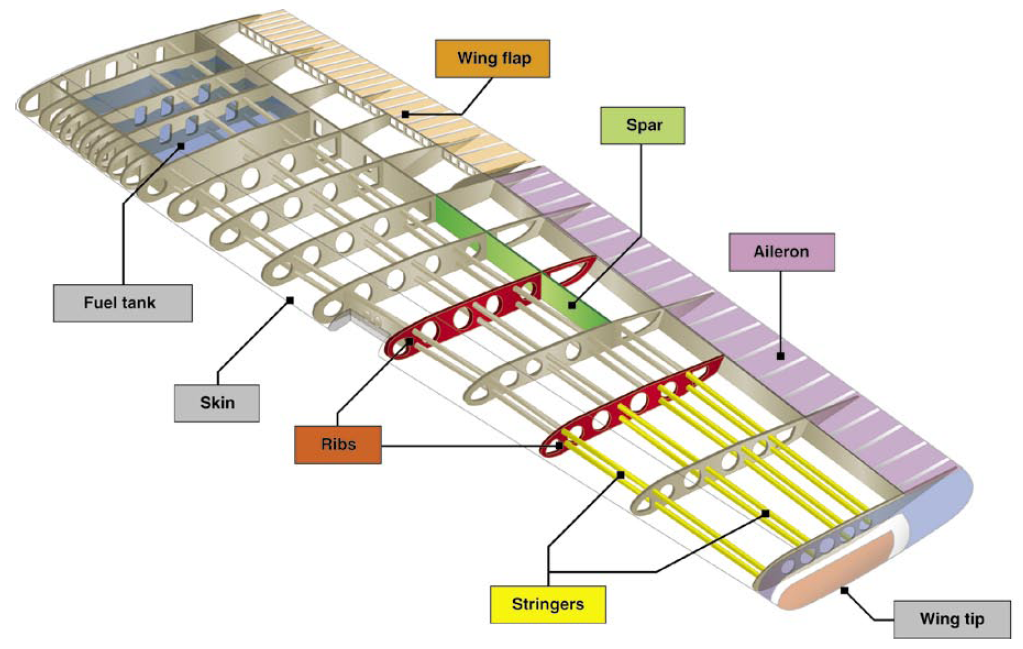
Cite this chapter
Kumar, S., Padture, N.P. (2018). Materials in the Aircraft Industry. In: Kaufman, B., Briant, C. (eds) Metallurgical Design and Industry. Springer, Cham. https://doi.org/10.1007/978-3-319-93755-7_5
Download citation
DOI: https://doi.org/10.1007/978-3-319-93755-7_5
Published:
Publisher Name: Springer, Cham
Print ISBN: 978-3-319-93754-0
Online ISBN: 978-3-319-93755-7
eBook Packages: Chemistry and Materials ScienceChemistry and Material Science (R0)