
Abstract
This paper presents a kinematic and dynamic analysis of two planetary geared nine-speed automatic transmission ZF9HP and W9A700, on which numerical results are used to compare their level of performance. The study of these two transmissions aims to highlight the advantages and disadvantages of both constructive solutions, knowing that through kinematic synthesis process seeks to choose the optimal final architecture by a high number of feasible kinematic schemes.
Access provided by Autonomous University of Puebla. Download conference paper PDF
Keywords
Introduction
In the powertrain system of the motor vehicles, the main function of the transmission is to adjust the running states and operating characteristic of the engine at driving conditions of the vehicle, in order to optimize fuel consumption and dynamic driving characteristic so as to maintain the vehicle controllable and safe, as well as to enhance passengers comfort. In mechanical discrete transmissions the gear ratio is defined by the speed stage of gearbox and changed depending on operating parameters of the engine and vehicle, carried out by the driver, according to the driving conditions.
In the designing phase of mechanical transmission of motor vehicle, the most important steps are the setting of gear ratios, a process known as the setting of speed range of gear stage of gearbox and choosing the suitable kinematic drivetrain, a process known as synthesis of kinematic schemes. The speed-ratio arrangement of gearbox involves the determination of kinematic characteristics and establishing of gear ratios after reports about the dynamic and traction performances of vehicle or according to criteria related to fuel consumption (Stoicescu 2007). The lowest and highest gear ratios values of gearbox are determined, in general, in order to obtain required acceleration or traction performance and respectively to achieve an imposed maximum speed. Usually, the number and values of intermediate gear ratios are determined in order to obtain equal ranges of the engine speed or vehicle speed in each gear, and to obtain equal intervals of traction force variation in neighboring gears.
The fuel consumption of an internal combustion engine represent a function dependent on vehicle speed and loading conditions as rolling parameters, that taking in account gear ratios, can be transformed into a function dependent on load and engine speed. Studies on the influence of gear ratios establishment on fuel consumption (Stoicescu 1998; Golebiewski and Stoeck 2012), reveals that by increasing the number of gears and use as much possible the higher gear stages, generate a significant reduction in fuel consumption and thus emissions, due to placement of operating speeds in the economic range of the engine speed.
Increasing the number of gear steps, especially by adding of overdrive speed-ratios, given the presented advantages, is an obvious tendency of manufacturers of gearboxes, so that currently exist cars equipped with automatic transmissions with a number of eight and even nine gears. These may include eight-speed automatic transmissions ZF8HP and AISIN TL 80SN both with two overdrive gears and nine-speed automatic transmissions W9A700 and ZF9HP with three, respectively four overdrive gears.
Analysis Methodology of Gearbox Kinematic Scheme
The synthesis process of kinematics structures based on graph theory elements (Hsu et al. 1994) significantly reduce the number of mathematically possible variants at a number of functional variants called feasible variants. Choosing the optimal kinematic scheme of a number of feasible variants involves analysis of all these constructive solutions.
Analysis of kinematic schemes for a planetary gearbox is an absolutely necessary stage in the synthesis process, because in order to establish the optimum kinemtic scheme that leads to required speed ratios and to fulfill certain constructive requirements is needed to comparing parameters that must be determined and that are interested in functional terms. Usually, in the conceptual phase of gearbox design the necessary constructive requirements are linked to compactness, mass, volume, overall dimensions and robustness.
The kinematic structures of nine-speed automatic transmissions ZF9HP and W9A700 developed and manufactured by ZF Friedrichshafen AG, respectively Daimler AG, presented in Figs. 1 and 2, are the result of analysis and synthesis process of complex compound planetary mechanisms with four degree of mobility. The difference between the presented automatic transmissions in terms of kinematic structures prove the imposition by the manufacturers of different construction requirements and various functional restrictions that may be highlighted by analyzing these kinematic schemes.

Kinematic structure of ZF9HP gearbox

Kinematic structure of W9A700 gearbox
The functional parameters calculation of presented kinematic structures can be done based on algebraic or matrix methods, which involves to successively follow several defined stages (Ciobotaru et al. 2005). Matrix based method that is applied in this case, provide complete informations about powerflow circulation and allows to use mathematical programs in a iterative way that reduce the time for the calculations. The working procedure is presented in the following stages.
-
1.
Identify input and output shafts, the number of simple planetary gearset and their typology, the number of coupling elements (clutches and brakes) and determine the values of constants K of all simple planetary gearset according to gear ratios and gearshifting sequence on Tables 1 and 2.
Table 1 Shifting table of ZF9HP gearbox Table 2 Shifting table of W9A700 gearbox The values of constants K for all four simple planetary gearsets of ZF9HP and W9A700 transmissions are presented in the Table 3, wherein \( i_{i} \) (\( i = \overline{1,9} \)) and \( i_{R} \) represents forward, respectively reverse gear ratios values according to gearshifting sequences.
Table 3 Calculus relations and acquired numerical values of simple planetary gearsets constant K -
2.
Build equivalent nodal structure and identifies the number of its joints. A joint of this network representation is a intersection point of at least three links between external elements of planetary gearsets, coupling or braking elements and input or output elements of kinematic scheme (Figs. 3 and 4).
Fig. 3 
Network structure of ZF9HP gearbox
Fig. 4 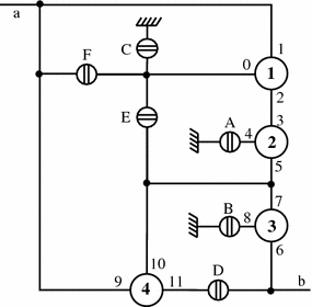
Network structure of W9A700 gearbox
-
3.
Number external elements for all m simple planetary gearsets of kinematic structurer according to rules contained in Table 4.
Table 4 Representation of planetary gearset elements and numbering rules of elements in a kinematic structure -
4.
Identify connected external elements according to kinematic or equivalent nodal structure; the link between any two external elements connected p and q leads to equations of the form:
$$ \omega_{p} - \omega_{q} = 0 $$(1)wherein \( p,q \in [0,3m - 1] \)
-
5.
Identify external element connected to the input shaft of gearbox and initializes his angular velocity value with the unit value:
$$ \omega_{p} = \omega_{a} = 1 $$(2) -
6.
Identify external element connected to the output shaft of gearbox.
-
7.
With coefficients of angular velocities and free terms it builds the matrices \( C_{V} \), respectively \( T_{V} \) for each gear stage. The matrix C it has a quadratic form and comprise a number of rows and columns equals to the number of external elements of all planetary gearsets. The first m rows of coefficients remains the same for all gears, wherein the coefficients of other rows are changed according to the equation corresponding to angular velocities restrictions introduced by the shifting elements. The general kinematic equations of simple planetary gearsets that form the kinematic structure of gearbox are under the form of:
$$ \omega_{3j - 2} + K_{j} \omega_{3j - 1} - \left( {1 + K_{j} } \right)\omega_{3j - 3} = 0 $$(3) -
8.
To form a gear stage is needed to engage certain coupling or braking elements. The number of engaged elements must be one unit smaller than the number of kinematic structure degree of freedom. In this case, the angular velocities restrictions are under the form of:
$$ \omega_{p} = 0\;{\text{for braking elements}} $$(4)$$ \omega_{p} - \omega_{q} = 0\;{\text{for coupling elements}} $$(5)wherein \( p,q \in [0,3m - 1] = 0 \).
The presented relations forms a determined algebraic equations system with matrix form:
$$ C_{V} \times V = T_{V} $$(6)wherein V is the angular velocity matrix values of external elements of planetary gearsets.
Finally, are determined the angular velocity matrix for each gear stage:
$$ V = C_{V}^{ - 1} \times T_{V} $$(7) -
9.
To calculate the distribution of power flow, with coefficients of torque and free terms it builds the matrices \( C_{T} \), respectively \( T_{T} \) for each gear stage. In the construction of matrix \( C_{T} \) are used the relations of torque equilibrium and distribution on planetary gearsets elements, the relations of torque equilibrium on nodal scheme joints and the restrictive relations introduced by shifting elements.
The torques that loads external elements of planetary gearsets satisfies the equation pairs:
$$ \left\{ { - K_{j} M_{3j - 2} + M_{3j - 1} = 0} \right. $$(8)$$ \left\{ {M_{3j - 2} + M_{3j - 1} + M_{3j - 3} = 0} \right. $$(9)For identified joints the equilibrium equations are under the form of:
$$ \mathop \sum \nolimits M_{r} = 0 $$(10)wherein \( r \in [0,3m + n_{cb} ] \) and \( n_{cb} \) are the number of all coupling and braking elements. In the calculation, the torque that loads the input element, corresponding to the input shaft, are initialised with unit value:
$$ M_{a} = 1 $$(11)In this case, the restrictions are imposed by the coupling and braking elements that remain disconnected in each gear stage, and are represented by cancellation of their load torques:
$$ M_{f} = 0 $$(12)wherein \( f \in [0,n_{cb} ] = 1 \).
The matrix of torques values that loads external elements of planetary gearsets and shifting elements in each gear stage are:
$$ M = C_{T}^{ - 1} \times T_{T} $$(13)


In the following sections of paper are presented graphic representations of results acquired by application of presented methodology, whose interpretation allows to identify the functional particularities and efficiency grade of both constructive solutions.
Gearboxes Angular Speed Analysis
In the synthesis process of kinematic structure of automatic gearbox the angular velocity of planetary gearset elements represent an selective criteria of feasible kinematics schemes, because operating angular speed are limited to a critical value. The limited speed \( n_{cr} \) can be imposed by thermal and dynamic safe operating condition, but based on practical experience (Schaeffler Technologies GmbH 2014) can be taken into account additional criteria such as smooth running, sealing function and centrifugal forces, even if are provided favorable conditions of lubrication and cooling.
The determination of angular velocities of elements and further of radial acceleration and maximum centrifugal forces, allows to compare the level of bearing loads and to evaluate the level of comfort in terms of operating noise produced by the gearboxes.
The analysis of angular velocities of planetary gearsets elements highlights that the ZF9HP gearbox, in eight gear stage, realise the angular velocity multiplication of elements 7 and 10, both of them representing the commonly sun gear of planetary gearsets 3 and 4, with a ratio of 4.995 related to the input shaft. The maximum angular velocity ratio of W9A700 gearbox are acquired in the same gear stage, at the element 8 that represent ring gear of planetary gearset 3, and according with Fig. 5, it is a value of 2.663.

Maximum angular velocity ratios of the PG elements
The graphic representations of maximum angular velocity of planet gears in each gear stage are presented in Fig. 6. The maximum values of it, reported to the angular velocity of input shaft, are 4.831 for ZF9HP at planetary gearset 3 and 3.506 for W9A700 at the same planetary gearset number.

Maximum angular velocity ratios of planet gear in each stage
From Fig. 7 it can be remarked that the planet gears of each planetary gearset of ZF9HP gearbox are higher angular velocities than in the case of W9A700 gearbox.

Angular velocity ratios of planet gears for all planetary gearsets (PG) in each gear stage
In the operation of gearbox, the difference between angular velocities of coupling elements has a major influence on the parameters regarding to passengers comfort and dynamic performance of vehicle when gearshifts occurs and also, represent an appreciation factor of drag torque loss in open multi-plate clutches or brakes.
The power loss through friction in open shifting element \( P_{fr} \) and drag torque \( T_{fr} \) are defined by mathematical relations (Dong et al. 2015):
wherein N is the number of friction facings, \( \mu \) is the lubricant dynamic viscosity, h is the lubricant thickness, \( \varDelta \omega \) is relative angular velocity difference, \( r_{o} \) is the outer radius of friction plate and \( r_{i} \) is the inner radius of friction plate.
The level of comfort during each gearshift depends on relative angular velocity of friction plates of the coupling element and can be translated in jerk and variations of vehicle acceleration.
The graphic representations shows in Figs. 8, 9 and 10 provides informations about relative angular velocity ratio during gearshifts. It turns out that the maximum relative velocity ratios of shifting elements are recorded in the case of ZF9HP gearbox, on dog clutch A, at shifting by the driving mode in reverse mode and backward. According to Table 1 that shows the shifting elements logic, result that the dog clutches A and F are released one-by-one at upshifts 4–5, respectively 7–8, situations where the transmission will be in complete neutral mode for a short time and will lead to a brief interruption of torque delivery. The engagement of dog clutches A and F occurs at downshifts 9–7, 8–7, respectively 7–4, 6–4, 5–4. According to Fig. 10, the downshifts 9–7, 7–4 and 6–4 occurs at high values of relative angular velocity of 2.35, 2.581, respectively 1.878. Due to the design of the shifting elements A and F and their special conditions for syncronising at high relative speed, the program of ZF9HP transmission control unit allows downshifts with just over a gear step jumps. Therefore, are allows downshifts 9–7, 8–6, 7–5, 5–3, 4–2, 3–1, and the exclusion by program of downshift 6–4 is due to high relative speed at engagement of dog clutch A. It detects a high ratio of relative angular velocity of 2.138 at downshift 4–2, but this is allowed because it doesn’t involve engagement of any other dog clutch.

Relative angular velocity ratio for upshifts sequence

Relative angular velocity ratio for downshifts sequence

Relative angular velocity ratio for “kick-down”
The downshifts with 3, 4 or 5 gear stages jumps are eliminated from shift pattern due tot the difficulty in syncronisation process, especially in situations 8–5, 8–4 or 9–5 which implies simultaneously engagement of both dog clutches. The downshift 9–7 with a high relative angular speed ratio is absolutely necessary to obtain high acceleration performance of vehicle during high speed passing maneuvers through kick-down shift, but involves a long shift time due the syncronisation process.
The advanced algorithms for downshifts 9–7, 8–7, 7–5, 1-R and shift R-1 comprise a complex logic of syncronisating process. If the transmission control module starts to select a shift that requires one of the dog clutches, it send an information at electronic control unit of engine in order to adjust the engine to a specific angular speed. To assist speed syncronisation of the two dog clutch component, the engine increase or decrease torque and angular speed. In situation which are needed to increase angular speed, the transmission control unit commands the slip of one or more friction clutches until the components of the dog clutch are moving at the same speed. The actions of complex control algorithms embedded in controller software, during syncronisation, are translated into higher wear of friction elements that affect reliability of transmission, and also in limiting of dynamic performances of vehicle, both of these consequences forming a disadvantage compared to W9A700 transmission.
To comparative analysis of losses due to the frictions of open shifting elements, according with Eq. (15), the drag torque depends on number of friction faces and overall dimensions of friction plates, which in turn are calculated to transmit or to resist at maximum torque achieved in operation. Therefore, taking in account assumptions that both gearboxes use types of lubricants with the same value of dynamic viscosity and the thickness of lubricants of plates in disengaged state are the same, is considered that the product between relative angular velocity ratio and maximum torque transmitted to the shifting elements represent a comparison parameter of friction loss level.
The graphic representation on Fig. 11 shows the level of friction losses in both gearboxes in each gear stage. To highlight the potential of reduction of losses by using of dog clutches, also is presented the situation of losses level in the gearbox namely ZF9HP* in which A and F are multi-plate clutches. Note that, including the use of dog clutches, in seven of ten gear stages the ZF9HP gearbox are higher losses than W9A700.

The level of drag torque in all open shifting elements
Gearboxes Torque Loads Analysis
The torques acquired in operating conditions loads the gears, shafts and shifting elements, and their maximum values, according to calculation of resistance, are those that dictate overall dimensions of internal organs. Regarding the torques that loads shifting elements, as shown in Fig. 12, finds that the kinematic structure of W9A700 gearbox is advantageous because it achieves a maximum torque ratio of 2.775 at brake D, compared with maximum value of 3.852, at brake B, of ZF9HP gearbox. Also, four by six shifting elements of W9A700 are loads with lower values of torque than ZF9HP gearbox. The maximum values of torque that loads each gear element of planetary gearsets and its corresponding shaft are presented in Fig. 13.

Maximum torque ratios of shifting elements

Maximum torque ratios of planetary gearsets elements
Gearboxes Powerflows and Efficiency Grade Analysis
For a more detailed analysis of operating sitations of gearboxes, in Figs. 14 and 15 are shown the powerflows in gear stages with speed ratio different by one unit.

Powerflows of ZF9HP gearbox in each gear stage

Powerflows of W9A700 gearbox in each gear stage
The ZF9HP gearbox provides a gear stage using a single planetary gearset, two gear stages using two simple planetary gearsets, four gear stages using three simple planetary gearsets and two gear stages using all four simple planetary gearsets. In the gear stages 6, 7, 8, 9 and reverse the powerflow is transmitted on two or more circuits. It stands the overload of simple planetary gearset 1 in reverse gear stage by a power ratio of 1.491 and a internal parasite powerflow that causes drastic reduction of efficiency. Internal parasite powerflow are also in gear stages 6, 7 and 9.
The W9A700 gearbox provides two gear stages using a single planetary gearset, three gear stages using two simple planetary gearsets and four gear stages using three simple planetary gearsets. In gear stage 1, appears an internal parasite powerflow and the overloading of simple planetary gearset 1 with a power ratio of 1.851. Also, in gear stages 5 and 7 it appears an internal parasite powerflows and the overloading of planetary gearset 4 with power ratios of 1.647, respectively 1.214.
Power losses due to gear meshing, as presented in equivalent nodal schemes of gear stages are dependent on powerflow modes. Knowing that the directions of powerflows in each gear stage, mechanically efficiency grade was determined, the results beeing presented in Fig. 16.

Efficiency grade of gearboxes
It finds that the ZF9HP gearbox is more efficient in lower gear stages, for example 1, 3, 4 and 5, while the W9A700 gearbox are more efficient in higher gear stages 6, 7, 8, 9, and in reverse gear.
According to presented methodology, because the input angular velocity and torque were initialised as one unit, the values obtained through calculation for functional parameters doesn’t represent real values, but ratios of this parameters reported to input variables.
For example, the output power presented in Figs. 14 and 15 represent the power ratio that is the same with efficiency grade values.
Conclusions
For determination of functional parameters values is applied a matrix-based analysis method, which allows to use a mathematical software in a systematic mode by passing through well establish steps. The functional parameter results shows that the synthesis of kinematic schemes in order to fulfill constructive requirements leads to kinematic structures that doesn’t provides maximum performances related to operating conditions and backwards. The design requirements of ZF9HP transmission regarding to space installation optimization, and in particular the transmission length limitation, in order to allow using in vehicles with transverse engine, provide a kinematic structure with two complex Ravigneaux and Simpson planetary gearsets. This arrangement of simple planetary gearsets and the placement mode of shifting elements in kinematic structure provide difficile operating condition that limit performances compared to W9A700 transmission due to the high value of functional parameters like angular speed, radial acceleration, torque loads and relative angular speed of internal elements. Due to the relative higher angular speed and to the integration of dog clutches in shifting elements that are need to synchronisation in engaging process, can’t be used certain shifting possible sequences, from shift pattern being eliminated 6–4 downshift, so that are limited dynamic performance in terms of vehicle acceleration in condition of high speed passing manoeuvres.
The need of dog clutch synchronisation at high value of relative angular speed, like situation of 9–7 downshift, impose using of advanced control algorithms and leads to decrease level of comfort due to the jerk, variation of linear acceleration of vehicle and engine torque limitation during certain gearshifts.
References
Ciobotaru T et al (2005) Transmisii planetare pentru autovehicule militare. Editura Academiei Tehnice Militare, Bucuresti
Dong P et al (2015) A method of applying two-pump system in automatic transmissions for energy conservation. Adv Mech Eng 7:1687814015590306
Golebiewski W, Stoeck T(2012) Effect oh high-speed traction gearbox ratio on vehicle fuel consumption. Teka Comm Monit Energ Agric 41–46
Hsu C-H et al (1994) Automatic synthesis of displacement graphs for planetary gears. Math Comput Model 67–81
Schaeffler Technologies GmbH (2014) Planetary gear bearing arrangements in industrial gearboxes
Stoicescu AP (1998) On the capability of the fixed-ratio transmissions to reduce the automobile fuel consumption in driving cycle with constant accelerations. Paris, s.n
Stoicescu AP (2007) Proiectarea performantelor de tractiune si de consum ale automobilelor. Editura Tehnica, Bucuresti
Acknowledgements
The work has been funded by the Sectoral Operational Programme Human Resources Development 2007–2013 of the Ministry of European Funds through the Financial Agreement POSDRU 187/1.5/S/155420.
Author information
Authors and Affiliations
Corresponding author
Editor information
Editors and Affiliations
Rights and permissions
Copyright information
© 2016 Springer International Publishing Switzerland
About this paper
Cite this paper
Eugen, N., Gheorghe, B., Florin, O. (2016). Analysis of Complex Planetary Mechanisms Used in Nine Speed Automatic Transmissions of Cars. In: Andreescu, C., Clenci, A. (eds) Proceedings of the European Automotive Congress EAEC-ESFA 2015. Springer, Cham. https://doi.org/10.1007/978-3-319-27276-4_3
Download citation
DOI: https://doi.org/10.1007/978-3-319-27276-4_3
Published:
Publisher Name: Springer, Cham
Print ISBN: 978-3-319-27275-7
Online ISBN: 978-3-319-27276-4
eBook Packages: EngineeringEngineering (R0)