
Abstract
This chapter deals with the development of methods and tools for the concept structural design of lightweight decks and bulkheads of cruise ships by use of composite materials. This task of the HOLISHIP project dealt with the development of a decision-support solution for the assessment of decks and bulkheads that may be replaced by composite materials. For this purpose, an Excel-based tool was developed, which is optimising the inspected structural design with respect to cost and weight. This chapter explains how this solution was developed. Various designs are explored and tested, while test results are presented and conclusive remarks are made after each completed milestone.
This chapter quotes the “Public Report of Cruise Vessel Deliverable D10.1” of the HOLISHIP project, funded by the EU under the European Union’s Horizon 2020 research and innovation programme under the grant agreement No. 689074.
Access provided by Autonomous University of Puebla. Download chapter PDF
Keywords
4.1 Introduction
4.1.1 Design Challenges of Cruise Vessels
Cruise vessels are highly complex ships including a high level of outfitting for ship functions, high owner requirements towards design and performance as well as challenging operational conditions. These vessels are built by large and often specialized shipyards in Europe, supported by a wide range of SME suppliers.
Cruise vessels are traditionally designed and manufactured out of steel material. The material is robust, and both design and production processes are well established. Since the shipbuilding industry faces the challenge of reducing both emissions and costs, the use of lightweight materials is becoming increasingly important. While lightweight materials—especially aluminium—have a long history in shipbuilding, dating back to the 1950s, there is great potential for integrating fibre-reinforced polymers (FRP) into cruise ships. FRP can help to reduce mass in weight critical areas of the ship. However, the use of such lightweight construction materials not only affects the weight, but also leads to different mechanical and fire protection properties, as well as altered noise and vibration behaviour. It may be necessary to adapt the surrounding design to some extent when replacing steel by FRP in specific components. Production processes need to be adapted from the steel process when integrating FRP into the ship design. Last but not least, the cost of material and process will be influenced.
Generally, when considering lightweight materials in cruise vessels, the goal is to use them only in areas and components where it leads to improvements in the technical and/or economic performance of the ship. Hence, the designer needs to be able to compare and evaluate different aspects such as design integration, noise and vibration as well as cost and producibility of designs using conventional metals like steel or aluminium and fibre-reinforced polymers. Since the use of lightweight materials affects many aspects of design and process, it has to be addressed in the design right from the start. The different material behaviours, design options as well as production aspects have to be considered and harmonized. Thus, in order to decide whether the use of lightweight materials is a good choice for a certain component, the ship designer must be able to compare the economic and technical performance of a steel design to a lightweight design in the early design phases.
4.1.2 Objectives of the Application Case
The Cruise Vessel Application Case focuses on the integration of fibre-reinforced polymers (FRP) for a SOLAS passenger vessel. Specifically, a structure on the sundeck of a cruise vessel is being investigated (see Sect. 4.2 for more details of the application case). At this position (upper decks) it is especially critical to have increased weight—since the centre of gravity is shifted upwards, the ship becomes less stable due to the reduction of the transversal metacentric height (GMT) and draft problems can occur. Hence, it is of great importance to save weight in this area. Therefore, the possibility to replace the conventional materials (steel, aluminium) by fibre-reinforced materials is investigated.
For this application case, the first objective is to investigate the design integration of FRP components considering owner, class, and yard requirements as well as elaborating different design cases. The second objective is to assess the noise and vibration behaviour of the new materials. The third objective is to develop a tool to compare the producibility and cost of different design options including retrofitting and advanced outfitting aspects and to apply it to the sun deck application case.
4.2 Design Integration
4.2.1 Introduction to Design Integration
When changes are made to an existing design with an established process, design integration needs to be considered. This means addressing the integration of a new design aspect or component, which may involve a material change, into the existing shipyard process.
The approach here is to intervene as early as possible in the shipbuilding phase in order to be able to react to necessary subsequent changes. The phases/milestones of the ship design process are explained in more detail in Sect. 4.4. In this context, a scenario is described, which is intended to explain the integration more detailed.
This chapter also looks at the conventional steel solution and the advantages of replacing it with composite materials. Furthermore, the individual requirements that play an important role in the integration of a new material on a cruise ship according to SOLAS regulations are considered. SOLAS is the abbreviation for Safety Of Life At Sea. It contains rules and guidelines that should lead to the safe production of a ship.
Below is a brief introduction to the topic of fibre composites and the advantages they offer. Afterwards it is described what the results of the project goal are and what challenges have to be overcome.
Composites are materials, which consists of at least two different components. They combine the positive properties of the different materials. They usually consist of reinforcement fibres and a matrix surrounding them, see Fig. 4.1. Fibre composite materials are characterised by the fact that the fibres are mainly responsible for the stiffness and strength of the part while the matrix has to keep them in place and distributes the internal stresses between the load bearing fibres and at the same time protecting them from environmental impacts. Since the fibres mainly determine the mechanical properties of the composite material, their orientation is decisive for the mechanical performance of the later component.

a Unidirectional layer, here with square fibre packing b Multi-layer composite consisting of individual layers bonded together (Schürmann 2007)
It is well known that fibre-reinforced polymers are ideally suited for lightweight constructions. In the last decades, many applications in the aerospace and automotive industries have proven their suitability. However, to benefit the most from the use of composites, the design needs to be adapted to the specific material behaviour. To exploit the full potential of fibre composites, it is not sufficient to replace the material while keeping the design. The design of the component and the material properties define each other when using composites. Since the goal of the WP10 was to provide the designer a tool to compare the cost and benefits of different materials and design options in a very early design phase, without too much effort of looking into specific composite details, it was not feasible to generate an optimal composite design at this design phase though. Instead, the focus was set to taking the first step for the introduction of this new material group in the cruise shipbuilding industry and showing the potential of composites in comparison to standard materials by using the developed tool. While not changing the overall design of the application case (spatial geometry etc.) the design was kept and scaled to a unit cell panel, able to compare the influence of the different material approaches. To exploit the maximum potential of a lightweight approach, the design of the complete surrounding structure (room geometry etc.) has to be changed.
The goal of this study is to give the designer an estimation of the benefit of integrating composite materials in large structural panels, such as walls (bulkheads) and decks. As there are currently no composite materials on the market that meet all regulations and guidelines (especially IMO FTP Code) necessary for the approval process for SOLAS cruise ships, the first step was to work with composite panels with fictitious material properties, but foreseeing the option to complement the database as soon as suitable panels are available.
Currently, the conventional material for production is steel. As soon as the ship becomes weight critical (due to draft or damage stability requirements), the usual practice is to change the materials. This means that steel is replaced by aluminium, wherever possible. The procedure is described in more detail in Sect. 4.2.4. For the realization of the project, the already built cruise ship “Norwegian Gem” (see Fig. 4.2) was chosen, because it had the conditions that would require a change of material. The application case refers to the upper decks of the cruise ship.

Cruise vessel “Norwegian Gem”
In this chapter, first of all the Application Case (AC) is described in more detail in Sect. 4.2.2. This includes the initial situation and the adjustments required to achieve a successful result at the end of the project. In order to meet the objectives, the requirements of the classification society, shipping company and shipyard must be met. These are described in Sect. 4.2.3. In Sect. 4.2.4, the typical design phases of the shipyard are described. In Sect. 4.2.5, the different design options that have been investigated in this study are presented.
4.2.2 Application Case Cruise Vessel
This application case was selected to be representative for the future application area of the developed tool. The tool should automatically provide information about which walls and decks can be replaced by using composite materials. The selection should be made in compliance with and in consideration of the characteristics, such as fire protection classes, ship specific requirements as noise & vibration characteristics and mechanical requirements.
In the case of the Norwegian Gem, it was determined prior to the start of the detail design phase that the ship could become weight critical. This was the reason to consider making the cruise ship lighter without removing accommodation areas from the ship or making them smaller. The design phases of a ship until completion are explained in more detail in Sect. 4.2.4. As the ship’s centre of gravity got critical, the upper deck structures were considered for replacement, and it was analysed how and where an economic reduction in weight could be achieved. For the application case a deckhouse on the sundeck of the cruise ship “Norwegian Gem” was chosen, which was originally intended to be made of steel. A picture and a 3D CAD model of the application case are shown in Fig. 4.3 and in addition a technical drawing in Fig. 4.4. The structure consists of a deckhouse with several rooms of different use categories on deck 14 as well as on deck 15 of the ship. The structures of the deckhouse to be analysed can be categorized either as deck panels or as bulkheads. This and the fact that a material change had been made, makes this application a good example for the tool to be developed.

Real application case and 3D-CAD model

Top down view of Deck 14: technical drawing with area names AC (Air Conditioning)
As can be seen in the figures (see Figs. 4.3 and 4.4), the geometry is complex due to bevels and recesses. Due to this fact, the CAD model of the application case was adapted and only plane structures are considered as the input structures for the assessment. This modification simplifies just the input and has no negative influence on the output of the tool, because mainly plane structures are found to be suitable for the use of FRP. These plane deck and wall structures can be found in a very huge amount on a cruise ship.
For a better view, Fig. 4.5 shows a side view of deck 14. On this drawing, the rooms of the application case are shown with information on the space category and fire protection classes according to SOLAS. The red-circled numbers indicate the space category according to the SOLAS listed in Table 4.1. In combination with the neighbouring area, the insulation for the fire protection can be determined.
For example, the right air conditioning room in Fig. 4.5 is marked with a 10 and thus is a tank, void or auxiliary machinery space with little or no fire risk (see Table 4.1). The adjoining space on the top left marked with a 5 is an open deck space.

Side view of Deck 14: technical drawing with area names AC Room (Air Conditioning Room)
The space categories of these adjoining rooms can be used to determine the correct fire integrity class for the wall connecting the rooms. To do so, it is important to distinguish between bulkheads and decks, because SOLAS defines different fire categories for bulkheads and decks as shown in Tables 4.2 and 4.3. In our example, the vertical separation is defined as bulkheads and the horizontal separation as decks. For the wall between the air conditioning room and the open deck space, the fire protection class A0 is determined from Table 4.2 by choosing the entry to space number 5 and 10. For bulkheads, the matrix is symmetric, i.e. the definition of the fire category only depends on the combination space categories on both sides of the wall, but it does not matter which space category is on which side of the wall. For decks, the fire risk of two adjoining spaces also depends on the information which of the rooms of below since this influences the fire spreading behaviour. Hence the matrix for decks in Table 4.3 is not symmetric. For the application case, the conservative approach was taken to always use to higher category where they differ.
In Fig. 4.6, a top view of the application case on deck 15 is shown. This depicts a mast mounted on the deckhouse on sun deck and has sloping geometries.

Deck 15 technical drawing (ΑC)
By adjusting the geometry to plane elements, the panel to be examined looks like in Fig. 4.7, but care was taken to keep the arrangement of the girder, subgirder and stiffener. Furthermore, the size of the panel corresponds to the actual size of a panels of the deckhouse. The dimensions of the profiles were also maintained. In this way, an investigation can take place as close to reality as possible and the results obtained are meaningful.

Original panel design
4.2.2.1 Fields of Application and Improvements
Fibre composite materials are intended to be used everywhere in cruise ships as soon as they meet all necessary requirements, which are explained in more detail in Sect. 4.2.3. This is not yet the case, as products on the market for example do not cover all necessary fire categories and comply with the non-combustible requirements stated in SOLAS. Theoretically, however, it is already possible that fibre-reinforced composites can replace conventional steel in areas even with the highest fire protection (A60) and acoustic requirements. Expecting that new materials will meet these requirements and will be available in the near future or changes in the rules will be made with the aim of a more performance based criteria instead of definition based ones, which is the current status for the permitted materials for bulkheads and deck structures. The work for this application case could only be carried out with this assumption and combining already known values with best guesses for unknown properties for composite panels. However, there are areas in the ship where it is not foreseeable that in the near future a deviation from steel as the constructing material will be allowed. Examples of these spaces are load-bearing structures capable to contribute to the global strength of the ship and main fire zone barriers. Further areas are defined in the SOLAS guidelines.
The main objectives for a change of material are to save weight and costs. By saving weight, the cruise ship consumes less fuel and therefore lowers the emissions. Another benefit of saving weight is being able to increase the number of cabins on the ship and thus generating a higher revenue. For the application case, costs will need to be compared to the use of aluminium since this is the current option to decrease the weight of structures when the weight becomes critical. Compared to steel, aluminium is more expensive and complex to handle. This is due to the joint between the aluminium structures the steel structure of the ship, which can only be achieved by using special explosive cladding. The use of fibre composites usually implies higher costs as well, but if fibre composite materials will be applied in a serial application, it is quite possible that they could become competitive.
For the use of composite structures, there are plenty of possible applications on a ship. It is conceivable to initially “only” build stores and galleys made of fibre composite material. The next step could be to continue manufacturing cabins. First, the necessary composite panels are created and calculated purely theoretically, as there are no ready to use products on the market yet. Research is already being conducted on usable products and it appears that suitable products will be available in the near future. In order to be able to act quickly and safely, an Excel-based tool is being developed which can provide automated information about whether a material change can be carried out in a particular area and how economical this is. A detailed description of the tool can be found in Sect. 4.4.5.
In order to cover further requirements that go beyond this application case, a few examples are given which should also be taken into account. On one hand, concepts have to be worked out how to proceed with structures with recesses. In doing so, the recording of the geometry and the dimensions play an important role. If geometries made of composite should have interruptions, an exact proof for the preservation of the required structural properties has to be provided to avoid an early failure. Furthermore, slopes or arcs must be considered. Although it is somewhat more complex to calculate these, these shapes are often found in ships. For the current application, an optimization regarding weight reduction is aimed at, but this only refers to the constant profile geometry. In this project, the walls and decks should have the same stiffness as the aluminium ones, to be able to compare the weight of the variants. These results can be found in Sect. 4.2.5 and refer to the comparison of aluminium to steel and composite as material.
In the next section, an overview will be given of the requirements, laws and guidelines, which must be complied with in order for composites to be applied as a material for a wall or deck. The SOLAS regulations of the International Maritime Organization (IMO) are described more in detail, as they play a decisive role in the construction of a cruise ship. These regulations are reflected in the class requirements, and apply to ship-owners and the shipyard.
4.2.3 Owner, Class and Yard Requirements
In the following, the essential requirements of the class, the ship-owner and the shipyard are explained.
4.2.3.1 Class Requirements
The class or classification society draws up technical guidelines for the design and construction of ships and issues them as construction rules. Building regulations contain, for example, strength calculations for the design and dimensioning of shipbuilding structures.
Classification societies monitor and document compliance with these guidelines when building a new ship and then issue it with a so-called class. The class is an assessment of seaworthiness and is the basis for ship and cargo insurance as well as for trading ships.
Today there are twelve internationally recognized classification societies worldwide:
-
American Bureau of Shipping (ABS), USA.
-
Bureau Veritas (BV), France.
-
China Classification Society (CCS), China.
-
DNV GL, emerged from Det Norske Veritas and Germanischer Lloyd, Norway/Germany.
-
Hrvatski Registar Brodova (CRS), Croatia.
-
Indian Register of Shipping (IRS), India.
-
Korean Register of Shipping (KRS), Korea.
-
Lloyd’s Register of Shipping (LRS), England.
-
Nippon Kaiji Kyōkai (NK), Japan.
-
Polski Rejestr Statków (PRS), Poland.
-
Registro Italiano Navale (RINA), Italy.
-
Maritime Register of Shipping (RS), Russia.
The requirements, such as structural properties for the application, are therefore determined by the classification society.
For the requirements for fire protection noise & vibration, however, the guidelines are the responsibility of SOLAS. The SOLAS (Safety Of Life At Sea) regulation contains many rules and restrictions to be applied with when building a ship. However, the most important ones for the project are those of fire classification, design properties and noise & vibration. The fire characteristics are determined by the class. More specifically, Chapter II-2 “Fire protection, fire detection and fire extinction” is the relevant SOLAS part that needs to be considered. It includes detailed fire safety provisions for all ships and specific measures for passenger ships, cargo ships and tankers.
They include the following principles:
-
Division of the ship into main and vertical zones by thermal and structural boundaries.
-
Separation of accommodation spaces from the remainder of the ship by thermal and structural boundaries.
-
Restricted use of combustible materials; detection of any fire in the zone of origin.
-
Containment and extinction of any fire in the space of origin.
-
Protection of the means of escape or of access for fire-fighting purposes.
-
Ready availability of fire-extinguishing appliances.
-
Minimization of the possibility of ignition of flammable cargo vapour.
Composites should be integrated on cruise vessels considering SOLAS guidelines. The biggest challenge here is to meet the specified fire protection classes. FRP may only be used in compliance with certain requirements, which would be:
-
For an area with fire class A60, the average temperature increase must not exceed 140 °C and the maximum temperature increase must not exceed 180 °C for 60 min. In addition, neither fire must not spread to other areas for 60 min.
-
It is similar for A30, A15 and A0, except that the temperatures here must be maintained for 30, 15 and 0 min respectively. However, here too the requirement is that the fire does not spread to other areas for 60 min.
-
There are areas with the fire classes B15 and B0. Here is the difference to fire class A that the maximum temperature of 225 °C must not be exceeded and the fire must not spread within 30 min.
-
A wall with fire class C, does not have to meet any special requirements in terms of fire protection. In a standard cruise ship, there are no areas with this fire class.
These are summarized in Tables 4.4 and 4.5.
In the application case, the design characteristics refer to the loads and dimensions. For example, point loads can occur on a wall because a television is installed at this point. However, it is also possible that two cabins are located directly next to each other and therefore the maximum depth of a wall must be observed.
Another reason for a minimum distance of two cabins can be noise & vibration. There are many areas on a cruise ship and some of them are exclusively for crew members and others are only for passengers. Since the goal is to maintain the highest level of comfort, there are clear guidelines on how much noise is allowed. However, this depends on areas and categories. Table 4.6 lists the areas that lead to so-called sound insulation indexes. The Comfort Rating Number (CRN) determines the level of well-being with regard to sound reduction. There are three categories 1, 2 and 3, whereby 1 is the highest rated category. This means that noise reduction is highest in this category and lowest in category 3. The three different categories are listed in Tables 4.7, 4.8 and 4.9. The values in these matrices are given in decibel dB. The higher the dB value, the higher the noise suppression.
Since the position of the room relatively to the wall or deck is not important, the “Sound insulation indexes for passenger areas” is symmetrical, thus it has no influence whether to start with the columns or rows to get the required sound insulation value of the surrounding bulkheads. As an example, we can take the areas 6 and 4, which are next to each other. If we now look at Category 1 in Table 4.7 on the left side of row 6 and column 4, we get the result of 38 dB. The same result is obtained if row 4 and column 6 are selected. The reading direction is therefore independent of each other (Tables 4.8 and 4.9).
4.2.3.2 Owner Requirements
The shipping company is the shipyard's customer and orders the cruise ship. The ship is built in close cooperation according to the wishes of the ship-owner and rules and regulations of the classification society. The shipyard assesses the feasibility of the project in compliance with all guidelines and safety standards.
It is particularly important for the ship-owner to stand out from the competition, which is why many cruise ships have a unique selling point. This and, of course, the excursion destinations, are intended to increase the market shares of the specific ship. On the Norwegian Gem, two highlights for example are a climbing wall on the upper deck (see Fig. 4.8) and the Crystal Atrium with a very large screen on which games can also be played.

(Source: TMN / Norwegian Cruise Line)
Climbing wall on the Norwegian Gem
Otherwise, the requirements of the shipping companies are often identical. Typical requirements are a long life-cycle of the cruise ship, modern appearance, innovative technologies on board, many passenger cabins and ample space to be filled with the specific wishes of the customer. Furthermore, the appearance must be attractive and the technology must be in perfect condition. With this application case, all requirements are covered at least partially. Since FRP’s do not corrode, they require less maintenance and therefore do not need to be replaced as often. The modern appearance is of course a matter of opinion, but composite material gives completely new design possibilities. Composite materials also are innovative technologies, because they have an enormous potential. There are many different combination and manufacturing possibilities, each of which is tailored to its intended use. More cabins and more space can be created, because the ship becomes lighter and it would be possible to implement more decks.
4.2.3.3 Yard Requirements
Roughly speaking, the shipyard's mission is to fulfil the customer's wishes, but with due regard to the laws and regulations. The aim of the shipyard is also to give its customers individuality and to gain a head start over competitors through unique knowhow. Therefore, the shipyard is constantly developing new solutions and concepts to increase effectiveness and sustainability. For this reason, the shipyard has its own standard (the “Werft Standard” of Meyer Werft GmbH & Co. KG). All requirements, laws and guidelines are observed or exceeded by the shipyards’ demands.
Production Aspects
An essential part of the introduction of composites is the consideration of the production aspects. Thus, it must be ensured that the value-added chain is maintained for the most part. At present, MEYER WERFT has one of the largest and most modern panel production facilities in the world. Of course, the competences at the yard are currently set on the production of steel panels and not on composite ones. Therefore, the composite panels would initially have to be purchased (as soon as the availability is assured). However, as soon as a fibre composite material has proven to be suitable, fulfils all the safety, comfort and design requirements, and is established on cruise ships, the next consideration would be to set up a production facility for fibre composites.
At the moment, it is often difficult to react to short-term changes from the customer. Often new planning and calculations have to be performed to react on these developments during the ship development process. It becomes very complicated when changing or moving areas. This requires new calculations for the centre of gravity of the ship, but also the consideration of cables and piping. In many cases “hot work”, like welding or burning, is no longer allowed when the ship is at an advanced stage of construction, which can lead to a lot of work even for minor changes e.g. something as trivial as burning an opening for cables. All neighbouring and surrounding areas are then inspected and evaluated. This can lead to the consequence that an adjacent area in which the hot work is to be carried out must be dismantled partly in order to minimize the risk of fire. With a composite wall this case could be avoided, because it can be cut without the need of hot work. Of course, the necessary structural properties must still be available.
4.2.4 Design Phases
In this section, the design phases are explained. To illustrate the process, a short scenario of what the work might look like using the results from this project is described. For a better understanding, the application case is chosen in the example.
After the rough details for the pre-contract phase have been clarified with the customer, the contract is signed and the following steps on the ship development process can be initiated. In this early stage for the preliminary weight prediction and stability calculations steel is used as the building material for all structural elements. Due to changes of the ship’s design or of some areas, the ship might become weight-critical and under certain circumstances, the vessel stability might get critical if the centre of gravity shifts upwards. One of the possible countermeasures to increase the ship’s stability is a change of the material of free-standing deckhouses on the upper decks, for example. An alternative material for the to be assessed structures would be aluminium, even if the substitution of steel with aluminium is expensive, since the connection between steel and aluminium is more complex by using explosive plating by specialist companies for example. Also the insulation of the aluminium structure to get the required fire classification has to be considered. Another possibility, which is currently in the focus of interest, is to use composites instead of steel or aluminium. The tool developed in this project is aimed to help at the decision which material is most suitable in respect to the specific requirements. With this tool the designer can quickly compare steel, aluminium and composite, determine costs, production time, and weight savings.
In order to benefit from the tool, it needs to be carefully considered at which point of the design process the tool ought to be used. It was a particular challenge to find a suitable shipyard process in which sufficient information on the ship areas was available and at the same time, sufficient flexibility was available to be able to react to short-term planning changes. Accordingly, the tool had to be developed based on the available information at this point of the process.
For this purpose, it was first necessary to know all processes and milestones of a ship. These are recorded in a so-called ship development process (SEP). This process is very comprehensive and describes the development of a cruise ship from kick off to delivery. It was clear that the tool should be integrated as early as possible in the design process, since the later changes appear the more expensive they will get. So the first milestones were examined more closely.
After careful research, the point within the ship development process is positioned after milestone B “Feasibility & Functions defined”, because at this stage of the construction process there is sufficient data to obtain a weighted statement from the tool and the construction process is still not so far advanced that a change would not be possible anymore. In this phase the tasks of the contractor are defined and an agreement is reached with the buyer. A general arrangement plan is aligned and a block plan is created. Final orders are then sent out.
4.2.5 Conclusions to Design Integration
Analysing the design integration for this application case provides a good foundation for gaining an edge over the competition when a composite material is approved and established on cruise ships.
As there are no composite panels on the market yet, fictitious assumptions for the tool input of the composite panels had to be made, which were then used for calculations and the assessment of the design. This often made it difficult to make the topic tangible for everyone. For this reason, the chosen panels were previously created with common materials. This made it possible to work with meaningful values.
A further hurdle was the integration into the shipyard process. Unfortunately, it is often the case that many decisions are based on experience, which is especially true in the pre-contract phase. Therefore, it was often difficult to get a reasonable statement about which results are available at what point in time in the ship development process. It is often the case that rough areas of the ship are planned, but without detailed values. Therefore, it is not unusual that during the development of a ship areas are relocated, redesigned or simply replaced.
Nevertheless, the composite selection tool developed on basis of these information can provide great added value for the engineer in a very early stage and indicates a direction what the influences of different material alternatives may result in. Because it is used where decisions about the material can still be reconsidered and with the stored figures, a statement can be made easily and quickly about how effective it might be to change the material of certain components.
4.3 Noise and Vibration
4.3.1 Introduction to Noise and Vibration
An important development in ship and seagoing structures is the application of non-conventional materials including synthetic materials and fibre reinforced polymer (FRP) materials with the aim of reducing structural weight, reducing building costs and combining functional properties (e.g. structural support and sound/ vibration isolation). Accommodation and workspaces on board cruise ships are subject to stringent noise and vibration requirements. This not only holds for the interior noise level inside a cabin, but also to the noise transmission of one cabin to the adjacent one. Noise and vibration prediction calculations enable nowadays the designer or ship builder to foresee already in an early design stage if these noise requirements can be met or if additional countermeasures are needed. For this purpose appropriate acoustic and dynamic assessment methods and tools are required. In this section the transfer of airborne and structure-borne sound and the damping of structural vibrations of composite structures are discussed.
4.3.2 Sound Reduction Index for Typical Sandwich Compositions
For the present application case of HOLISHIP, the frequency dependent transmission loss and the resulting weighted sound reduction index have been calculated for a targeted sandwich panel layout, see Fig. 4.9. The skin panels are glass-fibre reinforced resin (density 2000 kg/m3). The low stiffness of an additional mass layer in between skin panel and core has been neglected and the mass included by increasing skin layer density. Several core materials have been studied, see Fig. 4.9. Some are foam materials, like polyisocyanurate (PIR) which is typically used for rigid thermal insulation. Balsawood is a common core material but much stiffer and heavier. Not all core materials will have the correct fire-retardant properties. The PET and PE foams are known to have fire resistance. The Young’s modulus of all cores is much smaller than of the skin panels.

List of the studied sandwich compositions and material properties
The damping loss factors of the material are not specified. For this exercise, they were taken from database and literature values found for FRP and foam-like materials, typically 0.1–0.2. The damping loss factor of the core material governs the sound insulation at the core resonance frequency. To illustrate the sensitivity of the loss factor, the resulting RW value is increased by 3 dB if the loss factor is doubled.
In addition, geometrical and material properties have been changed to study the sensitivity of these parameters on the R’W value. For this purpose, an existing calculation model for sound insulation of composite building structures is used (see Gerretsen 1991). This is a model to simulate laboratory test. This means no flanking sound path, direct transmission through the panels only. Also, the sound field is diffuse, which means that sound waves reach the panel from all directions.
As a start, the effect of skin thickness is tested, by halving and doubling the layer thickness, see Table 4.10. As this directly affects the mass per unit area, insulation increases for increased thickness and consequently RW value increases, see left Fig. 4.10. Additionally, the core resonance decreases for increased skin mass, which is favourable for the high frequency insulation.

Calculated sound insulation R for various sandwich designs in third-octave bands
Next, the core layer is changed by halving core thickness and halving core density, both resulting in the same total mass properties. The effect on RW is only small, 0–1 dB. Insulation performance can be substantially improved by selecting a softer and thicker core material. This forces the core resonance frequency down, see centre Fig. 4.10. In this example, a foam core is used with equal density but much lower Young’s modulus. It results in an increase of RW of 7 dB.
The 4 mm layer attached to the FRP skins is quite light. Replacing the layer by heavier rubber layers (density 1300 kg/m3) with equal thickness can increase the RW value by 5 dB.
Finally, the skin stiffness was changed by using carbon fibres instead of glass fibres. This results in an increase of the Young’s modulus by a factor 3 and a longitudinal wave speed equal to that of aluminium. Since the mass is kept constant, effects can only be seen in the stiffness controlled high frequency range. Due to the stiffening the coincidence frequency, the frequency for which bending wavelength in the panel is equal to wavelength in air, decreases. This high frequency affect has no impact on the RW value.
A validation of the transmission loss and corresponding RW value prediction on a prototype sandwich panel in a building acoustics laboratory is recommended (see Dym & Lang 1983).
4.3.3 Simplified Design Tool
A simplified version of the acoustic model to assess the RW value in an early design stage was implemented in the developed Excel tool see Fig. 4.11. The material properties of the skin and core materials can be entered, and the insulation index is estimated. From the spectrum the RW value is calculated. High frequency coincidence effects are not implemented.

Overview of the RW Excel sheet
4.3.4 Attenuation of Structure-Borne Sound
Experimental analysis on a hybrid steel/composite ship structure showed a clear potential of hybrid superstructures in the attenuation of structure-borne sound in vertical direction (along deck transitions) (see de Regt 1981). It is much higher for a hybrid steel/FRP deck transition then for steel/steel. This is due to steel/FRP joints and interfaces introducing impedance mismatches. In horizontal directions (in-plane deck), no substantial differences with a steel reference case was observed.
4.3.5 Vibration Damping
Dynamic analysis on the same hybrid steel/composite ship structure showed that composite decks and bulkheads feature structural damping ratios ζ in the range of 4 to 7% of critical damping, as opposed to steel deck/ bulkhead structures where these values tend to lie below 1%. Hence dynamic amplification factors for composite structures range from 7.1 to 12.5, whereas for steel structures they are at least 50. Also composite structures seem to have a tendency towards a lower number of natural frequency and associated mode shapes in the frequency range of interest (0–30 Hz) compared to steel structures.
4.3.6 Conclusions to Noise and Vibration
The calculation results have shown that meeting stringent acoustic requirements with light-weight sandwich panels is not straightforward. The structural requirements to save weight by application of light-weight composite panels seems in conflict with the acoustic requirements.
Especially in the frequency range which is important for speech and music, the panel mass governs the sound transmission. The stiffness of the panel mainly affects the high frequency transmission. From this perspective the insulation of a partition panel can be improved by:
-
Increasing thickness of skin panels;
-
Adding additional layers.
However, there is a way to gain more benefit from a sandwich panel: the core resonance should be as low as possible. This can be achieved by selecting a low stiffness core layer (low Young’s modulus in combination with high core thickness) in combination with a high skin layer mass.
4.4 Producibility, Retrofitting, Advanced Outfitting and Cost
4.4.1 Introduction to Producibility, Retrofitting, Advanced Outfitting and Cost
Ship designers need to be able assess the feasibility of a FRP design compared to a conventional steel or aluminium design in the early design phase. This includes evaluating whether a new design can fulfil owner, class and yards requirements as described in Sect. 4.2.3 and assessing the impact on noise and vibration behaviour as described in Sect. 4.3. Additionally, cost and producibility of a new design are important selection criteria that need to be considered. Within this study, it was investigated how replacing a steel or aluminium design by a FRP design for the application case affects cost and producibility aspects. A tool for the assessment of cost and producibility as well as the feasibility regarding fire safety was developed and used to compare different designs for the application case. Since it is common to have small design changes in later stages of the production process of a cruise vessel, the ability of a new design to accommodate to such changes is also considered.
In this chapter, first relevant aspects regarding producibility, retrofitting and advanced outfitting are discussed. The methodology to determine costs for different design options is explained. Subsequently, the tool for the assessment of different designs and material choices is presented and applied to the application case.
4.4.2 Producibility
When new design alternatives are considered, usually the initial focus is on technical feasibility regarding design and classification criteria. If a design is considered feasible with respect to these aspects, the next important question is whether this design can be produced and integrated in the existing production process—i.e. to assess the producibility—and whether this can be done at a reasonable price. If a design is producible in general, different parameters such as geometric parameters may influence whether the production process can be implemented easily or is of a more complex nature.
In the early design phase, there is limited information available to assess producibility of different design alternatives. Since there is, however, the need to evaluate different design alternatives at this stage, a producibility assessment tool was developed based on a relatively simple dimensionless producibility score system elaborated in Work Package 4 of the HOLISHIP project. Utility functions are derived in particular for geometrical variation of the different parameter of stiffener panels. The tool demonstrates, that such parameter variations can be assessed well using such utility functions. The concept of this application case is to replace the existing aluminium deckhouse structure with panels and beam structures made of composite. For the concept of using available composite panels for the alternative design assessing producibility is reduced to assessing the assembly process of the panels to the steel ship structure including considering accessibility for the assembly and possible joining methods.
It should be noted that the exact implementation of the production process affects the cost of different designs (see Sect. 4.4.5). Hence, there is potential for optimizing costs by optimizing the production process. However, based on the information in the early design method, it is impossible to already include an optimized process. But it should be kept in mind when comparing costs that there is further potential for cost reduction of the alternative design, whereas the process for the current design usually is already optimized with respect to costs.
4.4.3 Retrofitting
Retrofitting is an important aspect in shipbuilding, especially in cruise liner and yacht markets, as the trends evolve fast with respect to integrated technologies, required equipment and interior fashion.
When retrofitting involves the installation of either heavy devices directly bolted to the bulkheads and decks, special considerations need to be taken into account if a composite sandwich type construction is involved. In that case, there are three main effects to be considered: out-of-plane and in-plane buckling due to the weight of the device, compression loads due to the fastening of the device, and bearing loads again due to the weight of the device. Buckling loads exceeding the design load of the panel might require re-dimensioning for higher stiffness, normally with thicker cores for weight optimization. Compression loads are a crucial design parameter for the core material. An increased compression load might require local re-dimensioning of the core, normally selecting a high-density core of the same type. Bearing loads act transversely to the fibres and normally require local reinforcements of ±45° plies. Another possibility would be that the device is fastened with wood-type screws in which case special considerations need to be taken concerning the sandwich core.
Penetrations introduce different design considerations related to fire resistance and pre/post-processing. The fire division category must to be maintained also with penetrations. This can be easily achieved if this is already considered in the design phase, but will need special care in case of repair and retrofitting. On the other side, penetrations would need special considerations when they are done on humid or weather-exposed areas, where it must be ensured that the core of the sandwich remains watertight at any time.
The tool is ready to integrate data for retrofitting as the assessment procedure is the same as for the preliminary design phase, which is explained in more detail in Sect. 4.4.6. The input will give information about the required fire division categories as well as sound insulation. The tool will then check if the requirements are achieved with the available panels configured in the panel catalogue. At this point, the panel catalogue should be updated with the new design considerations of the retrofitting, and the new panel reference list can be compared with the same references of the original list, knowing in this way which bulkheads and decks need to be post-processed. The format of the panel catalogue including update buttons for new panels is shown in Fig. 4.12.

Composite panel group in the panel catalogue
4.4.4 Costs
The early determination of costs and cost drivers in the production of shipbuilding elements increases the probability of meeting planned budgets and thus leads to profitable success in shipbuilding. Based on a reference panel of the project partner Meyer Werft, a cost calculation tool (CCT) was developed in order to make suitable statements about the production costs of a shipbuilding panel made of different materials.
4.4.5 Composite Selection Tool
4.4.5.1 Tool Description
Since it has been theoretically proven that significant weight savings can be achieved in classic shipbuilding by using future composite materials, a tool is developed which performs an assessment to determine whether the use of composite materials is suitable.
The assessment procedure implemented in the tool is elaborated in the following steps:
-
1.
The user provides an input file containing information on the deck and bulkhead panels that are to be assessed. This includes geometric dimensions, current material, weight, and existing fire division category. Additionally, the user can define parameters defining structural and insulation requirements and has the option to define fire division categories manually as well. These input variables are shown in Fig. 4.13. For example, the user can define the maximum allowable deflection, relevant safety factors, or the sound insulation level according to its crn (comfort rating number). Subsequently, the user has the choice of optimizing either weight or cost. The tool has been integrated into the HOLISHIP CAESES® design platform.
Fig. 4.13 
Input variables in the “cockpit” sheet of the tool

-
2.
With this input information, the tool will start the assessment of each panel. During the assessment procedure, the tool evaluates whether it is feasible to replace the original panel by a pre-defined selection of alternative panels defined in a panel catalogue. This panel catalogue contains a selection of aluminium and FRP panels as well as material data for steel panels. As explained in Sect. 4.4.3, the panel catalogue can be updated by the user at any time e.g. if new materials become available on the market.
Assessment of the feasibility of the alternative panels is based on the compliance of different design parameters to class, owner, and yard requirements. Specifically, three aspects are evaluated subsequently in the assessment procedure (each containing a few sub-criteria for compliance):
-
a.
Compliance of fire division class,
-
b.
Compliance of structural requirements,
-
c.
Compliance of sound insulation requirements.
-
a.
-
3.
The results of the panel assessment are presented in the “report” sheet.
This sheet serves as a simplified visual summary, allowing the designer to get a quick overview of the compliance assessment for each panel. As shown in Fig. 4.14, the designer will be able to see for all selection criteria whether compliance can be achieved using the alternative panels from the panel catalogue (where green means panel complies, red does not comply). These results help the designer understand where the problems can be and introduce changes in the panel catalogue accordingly, e.g. if most FRP panels in the panel catalogue fail to achieve compliance of the fire division class it is promising to look for different materials with better fire properties, if fire division achieves compliance but sound insulation requirements are generally not achieved then there is potential in finding materials with better sound insulation properties.
Fig. 4.14 
Compliance summary in the “report” sheet
-
4.
The last step is the weight and cost optimization algorithm. This algorithm is implemented in the “results” sheet and will select the best available option from the panels that where identified to be technical feasible in the previous step. Depending on the optimization criteria selected by the designer, the algorithm selects the cheapest or the lightest available option out of all technically feasible panels. In the result table (Fig. 4.15), for each panel the optimal selected material (aluminium or composite) is displayed together with the according optimal panel, i.e. out of several different composite panels with different mechanical properties and weight and cost in the panel catalogue the result table specifically identifies the best composite panel if composite is the best choice. For this optimal panel, the new cost and weight is determined and compared to the original cost and weight. If none of the alternative panels are feasible, the original material will be selected.
Fig. 4.15 
Results table
-
5.
An overview of the results is given in the result area of the “cockpit” sheet as shown in Fig. 4.16. The designer can see at one glance how many panels were analysed and for how many panels a replacement of the original panel by an alternative panel of the panel catalogue can reduce weight as well as which total weight savings can be achieved at which cost. The graphic results also display failure type distribution, giving a clear information on the suitability of the panel catalogue for the considered application.
Fig. 4.16 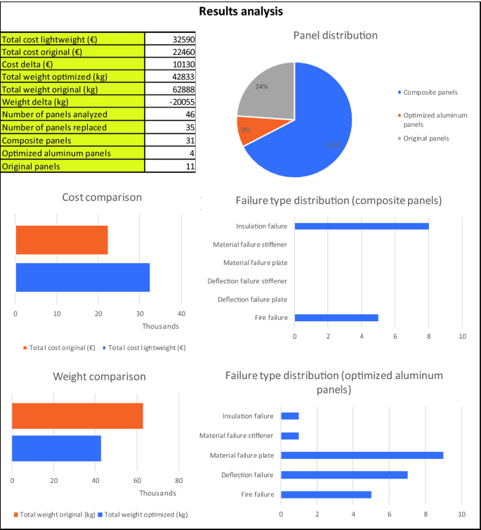
Results analysis box


4.4.5.2 Integration in CAESES®
This section describes the workflow performed to create the “Tool Input File” that is generated by CAESES® and consumed by the “Composite Selection Tool”.
Workflow
The procedure starts with the user importing an input geometry in CAESES® (see Fig. 4.17). The input geometry is preferred to be an stp/step or ascii file type where some of the naming arguments are preserved and transferred directly into CAESES®.

Workflow of CST Tool integration into the CAESES® platform
In CAESES®, a so called “Feature Definition” has been created. After having imported the geometry in CAESES®, the user needs to specify the scope that contains the imported geometry. The created feature includes the necessary commands to evaluate the panels within the scope. The panels are checked initially for their type (Bulkhead, Deck, Column) and then are used for detecting the existing rooms and floors. As a result, a plan view of the rooms and floors is created below the existing imported geometry where the user is requested to assign the room functionalities (Fig. 4.18). When this step is performed, the panels are sorted with respect to their dimensions (Long Dimension, Short Dimension, Thickness, Area) and fire category (A15, A30, A60, etc.) (Fig. 4.19).
The final stage before the initiation of the Composite Selection Tool would be the input file creation step. All obtained data from the panels is written into an input file which would be consumed by the Composite Selection Tool (Fig. 4.20).
Having run the Composite Selection Tool using the CAESES® provided input file, the user should be having the information of the assigned material to each panel. This data is brought back into CAESES® where the panels are renamed and coloured with respect to their assigned material, ready to be exported for further use.
4.4.5.3 Application of the Tool
The present application case used in this study the uppermost superstructure on a cruise liner which is currently built in aluminium. The aim of the tool, in that case, will be to provide information on whether it is possible to replace partially the original aluminium construction by composite plates or by aluminium plates with optimized properties. To do so, first, the panel catalogue has been updated with the data derived from the analyses conducted by SMILE FEM (see Sect. 4.2.2). This study compared several types of composite sandwich panels with or without local stiffening members, either of composite, aluminium, or steel. Pure aluminium and steel panels were also compared. The relevant strength and stiffness data were obtained, and the panel catalogue was updated with 5 composite panel types and 1 optimized aluminium panel type. In Fig. 4.15, the data for these considered composite panels are shown:

Application case model in CAESES®
-
Panel 1A60C: thin composite sandwich with steel stiffeners,
-
Panel 2A60C: thick composite sandwich panel without stiffeners,
-
Panel 3A60C: thin composite sandwich panel with aluminium stiffeners,
-
Panel 4A60C: thick composite sandwich panel without stiffeners to set different sound insulation or increased strength if needed,
-
Panel 5A60C: thin composite sandwich panel with pultruded composite stiffeners.
The shipyard provided an input data sheet with a suitable structure including data of all bulkheads and decks of the superstructure of the application case. The fire division category was set to a potentially applicable A0 and the optimization algorithm was set to optimization for the lowest weight. The results for the application case are displayed in Fig. 4.16.

Room functionality assignment in CAESES®
It can be seen that there is a potential benefit for weight savings by replacing 76% of the assessed panels by either composite panels (67%) or optimized aluminium panels (9%). A significant weight saving of almost 30% can be achieved with this replacement, but only at an increased cost of approximately 45%. In general, this means that the pre-selected panels in the panel catalogue are well-suited for the requirements of this application case. For most panels, a replacement is technically feasible. Where this is not the case, the failure type distribution shows that for the considered composite panels, compliance with structural criteria such as material and deflection is achieved for all panels. For some panels, however, compliance with fire and insulation criteria cannot be achieved. Aluminium on the other hand more often was not selected due to failing to meet material or deflection criteria.

“Tool Input File” generated by CAESES®
If the optimization algorithm would be set for cost optimization, the aluminium option will be dominant as the cost of the panels is set lower in the panel catalogue compared to composite panels, although the result would be a heavier structure. This option would also give the possibility to replace 76% of the bulkheads and decks.
To determine the best solution regarding to both cost and weight, the user can decide on different strategies. The approach suiting the current needs of Meyer Werft is to set a maximum allowable percent increase for costs. Since this is a typical two objectives optimisation, it is also possible to modify the tool and to implement another decision support method available to rationally decide about the best option.
In general, the results depend on some assumptions made in the early design stage. Hence, if the designer assesses this result, he should be aware that the real costs and weight savings, when using composites, might differ to some degree in the end. However, the results also well demonstrate that the designer can get a good idea of the weight savings potential, and the shipyard has a basis to decide if the option to reduce weight at this increased costs should be pursued further or not in the design process.
The present approach to replace a steel or aluminium construction 1:1 by composite materials does not take advantage of all possible benefits of composite materials, but it is a first step to introduce composite materials in the shipbuilding design process. There is still potential to further optimize the use of composites, reducing mainly logistic, production and material costs. Also, using the tool continuously in the shipyard will increase the data basis and allow the user to make more precise estimations in the future.
4.4.6 Conclusions to Producibility, Retrofitting, Advanced Outfitting and Cost
The composite selection tool (CST) developed herein serves the need of the shipyard to have a tool which can be used in the preliminary design stage in the most practical way. Since it was developed together with the shipyard, it takes into account not only the type of information that is available at this stage, but is also considering the data structure of the shipyard. In general, the input data needed to assess the composite panels would, however, be the same for any other shipyard. Hence, the tool could be used by other shipyards as well without any changes if the input data is provided in the exact same format. It has been developed with simple approaches and doing some compromises and assumptions as it has to be flexible tool, with the potential of analysing sets of many thousands of panels sometimes, even as part of an iterative process.
It is important to remark that the aim of the tool is not to provide final design parameters, because there is not enough information available at the early design stage to do so, so none of the modules have been developed with the aim to give detailed final design values. The calculations are based on simplifications which will serve the target of the tool of giving a global estimation with the highest possible accuracy. With respect to the application case, the results are based on a simple first comparative study where the designs of the composite panels can still be further improved. The design of highly optimized composite structures needs a very different approach than the classical isotropic plate-composed structures used in shipbuilding. Composite materials have significantly increased costs in comparison with steel or aluminium, but give the possibility to provide highly optimized topologies where each structure element has his customized properties. The application of this tool can only provide results for a given set of panels and is the first step in integrating composite materials. To benefit most from the use of composites, the ship designer needs to determine the most convenient way to design and produce those panels. This is a key to get the most interesting results from the tool for future applications.
The cost comparison tool developed in this work package implements a methodology to determine the costs of production processes for different materials. This gives the designer the option to compare costs by following a clearly structured process. Since process details for steel are at this point better known, cost estimates are more precise than for the composite process. Hence there is a need to study costs and the integration of composite construction techniques in the entire value chain of the yard in more detail.
Both the composite selection tool and the cost comparison tool enable the designer to evaluate the benefits and costs of different design options today already. The shipyard can maximize the benefit of both tools, however, by continually increasing the data basis in the future.
4.5 Overall Conclusions
Different aspects need to be considered when integrating FRP (fibre-reinforced polymers) into a SOLAS passenger vessel. Applying a new material is only possible if owner, class and yard requirements are fulfilled. An analysis of the requirements showed that the use of composites could contribute to meeting owner and yard requirements such as using innovative technologies. The use of composite structures particularly has great potential to support the objective of saving weight in critical areas. With increasing ship sizes, weight becomes critical more often especially in upper decks. The biggest challenge concerning the requirements today lies in meeting class requirements specifically for fire protection. There are currently no composite panels on the market that can fulfil all class requirements. It is however, expected that suitable materials and components will be available in the market in the near future.
For a smooth design integration, it is essential to choose the right timing for design changes within the design process. If a new design aspect or component is introduced at a very late stage, integrating it into the production will be more challenging and costly than when changes are made at an early stage. However, at an early stage available information on design details is limited, so the decision of whether or not to replace steel by composite or aluminium cannot consider all aspects that could be used to compare more elaborated design options. For the application case, a suitable milestone in the design phase was identified and the tool was developed for the use at this stage.
Another challenging aspect is the design philosophy when composite materials are introduced into a passenger vessel that is traditionally designed of metal. The greatest benefit of using composite materials can be achieved when a design is specifically tailored to composite material behaviour. This would, however, require detailed analyses and bigger changes in the complete design and production process, thus raising the hurdle for the shipyard to consider composite materials at all. Thus, to take the first step of integrating fibre-reinforced composites, the strategy is to replace existing steel or aluminium structures almost 1–1. This obviously still leaves further potential to obtain benefits from the use of composite materials in future designs. Within this strategy, there is still some degree of freedom to implement different design options for the considered panels such as varying stiffener spacing. These were analysed and the best option was identified.
Aside from structural properties, fire safety, and design integration, the noise and vibration behaviour of a new material is essential, effecting comfort of passenger and crew as well as possibly influencing the structural behaviour of the ship. The analysis of vibration behaviour showed that composite decks and bulkheads feature structural damping ratios ζ in the range of 4–7% of critical damping, as opposed to steel deck/ bulkhead structures where these values tend to lie below 1%. Hence dynamic amplification factors for composite structures range from 7.1 to 12.5, whereas for steel structures they are at least 50. Also composite structures seem to have a tendency towards a lower number of natural frequency and associated mode shapes in the frequency range of interest (0–30 Hz) compared to steel structures. Regarding acoustics, experimental results showed a clear potential of hybrid superstructures in the attenuation of structure-borne sound in vertical direction (along deck transitions). In horizontal directions (in-plane deck), no substantial differences with a steel reference case was observed. For the airborne sound transmission through sandwich panels, meeting stringent acoustic requirements with light-weight sandwich panels is not straightforward. By selecting a low stiffness core layer in combination with a high skin layer mass, the insulation performance of sandwich panels can be improved.
For the assessment of different material options, a cost tool (CCT) and a composite selection tool (CST) were developed. The cost tool is based on a detailed analysis of different process steps for the different materials. One challenge here is that the process for steel is known in detail and is optimized, while composite panels would be purchased from supplies in the first step and subsequently a process would need to be established first. Hence, the degree of available information on actual cost is more detailed for steel at this point. The methodology provided in the tool can, however, be easily applied by the shipyard to update cost estimates when knew information on the composite costs becomes available. The composite selection tool is based on comparing requirements to a catalogue of pre-selected aluminium and composite panels. The current selection is based on some assumed material properties, but the user at any point can easily update the panel catalogue in time.
Input and output of the tool was determined to suit the shipyards data structures and requirements and to be easily integrated into the CAESES® platform. A use by other shipyards would be possible without any modifications if input data is provided in the same format. Application to the present application case showed that it can be applied as intended and gives the designer a quick overview of how much weight savings can be achieved at which price when replacing aluminium panels by composite panels, if this is technically feasible. The results are based on some assumptions relating to cost, material properties etc. but in general they seem reasonable, with a potential for some weight savings at a higher cost. The tool also gives the designer an easy way to see how the panel catalogue can be improved by showing the failure distribution for the panels. To get the most use out of the tool in the future, it is essential for the shipyard to continue to extend the data basis for costs and available materials and their properties.
Abbreviations
- AC:
-
Application Case
- AC:
-
Air Conditioning
- CABIN:
-
TNO Software Tool
- CAD:
-
Computer-Aided Design
- CAE:
-
Computer-Aided Engineering
- CAESES®:
-
CAE System Empowering Simulation (Friendship Systems Software
- CCT:
-
Cost Calculation Tool
- CMT:
-
Center of Maritime Technologies gGmbH
- CRN:
-
Comfort Rating Number
- FEM:
-
Finite Element Method
- FRP:
-
Fibre-Reinforced Polymers
- HOLISHIP:
-
HOLIstic optimisation of SHIP design and operation for lifecycle
- IMO:
-
International Maritime Organization
- PE:
-
Polyethylene
- PET:
-
Polyethylene Terephthalate
- PIR:
-
Polyisocyanurate
- R’w:
-
Apparent Sound Reduction Index
- Rw:
-
Sound Reduction Index
- SME:
-
Small and Medium-Sized Enterprises
References
de Regt, M. J. A. M. (1981). Transfer of structure-borne sound to ship's cabins. Noise Control Engineering, Sept/Oct, 1981.
Dym, C. L., & Lang, D. C. (1983). Transmission loss of damped asymmetric sandwich panels with orthotropic cores. Journal of Sound & Vibration, 88, 299.
Gerretsen, E. (1991). Calculation model for sound insulation of composite structure—s/w tool CABIN (in Dutch), TNO report, TPD-HAG-RPT-91-0060, Delft.
Schürmann, H. (2007). Konstruieren mit Faser-Kunststoff-Verbunden. Springer: New York. ISBN 978-3-540-72189-5.
Author information
Authors and Affiliations
Corresponding author
Editor information
Editors and Affiliations
Rights and permissions
Copyright information
© 2021 Springer Nature Switzerland AG
About this chapter

Cite this chapter
Thellmann, AH., Schouwer, T., Mayland, W., Ferrer Mur, S. (2021). Development of a Tool for the Assessment of Lightweight Bulkheads and Decks Made of Composite Materials. In: Papanikolaou, A. (eds) A Holistic Approach to Ship Design. Springer, Cham. https://doi.org/10.1007/978-3-030-71091-0_4
Download citation
DOI: https://doi.org/10.1007/978-3-030-71091-0_4
Published:
Publisher Name: Springer, Cham
Print ISBN: 978-3-030-71090-3
Online ISBN: 978-3-030-71091-0
eBook Packages: EngineeringEngineering (R0)