
Abstract
The development and design of engineering systems using a methodical approach based on guidelines in the literature [16.1, 16.2, 16.3, 16.4, 16.5, 16.6] has been found to be a very useful approach. Such design methodology guidelines have also been applied to interdisciplinary development projects of this nature using aids such as requirements lists, functional structures, and the morphological box, to name just a few. During the design phase of the product development process, it is important to comply with the basic design rules: simple, clear, and safe [16.3]. Several examples that clearly show the realization of these three criteria are included in this chapter.
Access provided by Autonomous University of Puebla. Download chapter PDF
1 Design Theory
1.1 Product Planning Phase
It is possible to define the individual life stages of a technical product. These stages are often the basis for work done by the product manufacturer and the product user. Examples include schedules for the development of a product and maintenance plans.
Figure 16.1 shows the essential life stages of a product during its production and application. It is also possible to subdivide the individual product life stages into steps, which helps the product engineer to precisely categorize the activities involved in each stage.


Life cycle of a product (after [16.7])
1.1.1 Product Life Cycle Stages and the Technical Life Cycle
The life cycle of a technical product is closely linked to the general material cycle (Fig. 16.1). The cycle starts with an idea for a product, arising from a market or customer need. This is concretized in the first phase of product life: product planning. The result is that a task is set, which provides the basis for the second phase of product life: development and construction. At this stage, the implementation of the idea and/or resolution of the task to obtain a viable product takes place in individual steps. The life cycle then continues with the manufacturing process, in which parts are manufactured and the product is assembled and quality tested. This phase in the life cycle of the product ends when the manufacturer passes the product on to the distribution department.
This life-cycle stage is the interface to the application (i. e., the usage or consumption) of the product. Intermediate maintenance steps can help to extend its useful life. After the primary use of the product, it may be utilized again for the same purpose or for a different purpose (reuse/further use), or it may be converted into a secondary material that is used to create new products that are employed for the same purpose as the primary product (recycling) or for a different purpose (further utilization). Nonrecyclable components end up in a landfill site or are burnt to produce thermal energy.
Except for the recycling or landfill stages, this life cycle applies to physical products such as machinery, equipment, and devices, as well as to software products. It is usual for companies to employ such structuring techniques for product tracking.
1.1.2 Economic Life Cycle
As well as a succession of product life stages and/or concrete manufacturing and application steps, the life cycle of a product can be viewed in terms of economic data relating to the various stages of the product's life cycle. Figure 16.2 shows the relationship of each product stage to turnover, profit, and loss. It can be seen that before any turnover can be attained, the company must investment in implementation costs. The size of this investment is heavily dependent on the product. The company must recover this investment (i. e., it must break even) before it can begin to realize its ultimate goal: to make profits.


Life cycle of a product (after [16.3])
The profit zone is characterized by a growth phase and a market saturation phase before decline sets in through reductions in turnover and profit. At that point, sales and profits can be revived (e. g., through special sales and promotional activities), but usually only for a short period, so it is better to periodically establish rising life curves through the development of new products than to offset declining life curves of old products.
1.1.3 Product Planning
1.1.3.1 Importance
The first two phases of product life—product planning and product development—are among the most important tasks in industry. The continuous generation of marketable products provides the foundation for the economic success of a company. Because of the inevitable downturn phases for existing products or product groups (Sect. 16.1.1), the systematic planning of new products (i. e., an innovative product policy) must be implemented [16.4]. Strategies for product planning should not present a barrier to creative companies and their engineers; instead, they should play a supporting role as methodological aids.
1.1.3.2 Fundamentals
Product planning is performed based on the relationships in the market, in the business environment of the company, and in the company itself. These relationships can be defined as either external or internal influences on the company, particularly its product planning process. External influences include:
-
The global economy (e. g., exchange rates)
-
The domestic economy (e. g., inflation rate, labor market situation)
-
Legislative and administrative acts (e. g., environmental protection)
-
The buying market (e. g., the suppliers’ market and commodity market)
-
Research (e. g., government-funded research priorities)
-
Technology (e. g., developments in microelectronics or laser technology)
-
The market.
As such, the conditions of the market are crucial. A distinction can be made between a buyer’s market and a seller’s market. In the former, supply is larger than demand; in the latter, demand is larger than supply. In a seller’s market, production is the bottleneck; in a buyer’s market, products face strong competition from products produced by other companies, so the products must be designed and developed with this in mind.
Further criteria for market identification encompass:
-
Economic areas (domestic market, export markets)
-
New factors for the company (current market, new markets)
-
Market position (market share, strategic free rein of the company, the technical value of its products).
Internal factors include:
-
The organization of the company (e. g., product-oriented vertical or task-oriented horizontal organization)
-
The staff (e. g., availability of qualified development and manufacturing staff)
-
Financial strength (e. g., investment opportunities)
-
The size of the company (e. g., in terms of turnover that can be sustained)
-
The production fleet (e. g., with regard to certain manufacturing technologies)
-
The product program (e. g., with regard to components that can be adopted and predevelopment)
-
Expertise (e. g., development, marketing, and production experience)
-
The management (e. g., project management).
The influences listed are also termed the potential of the company.
1.1.4 Product Development
1.1.4.1 General Approach
The second phase of product life is development and construction. This is also often referred to simply as product development. To further structure this phase of product life, it is usual to break the stages down into individual steps. This procedural approach to handling construction tasks is based on general solution methods and/or working method approaches as well as the general relationships involved in building technical products. It is not a rigidly prescribed approach, but it is an essential tool for the engineer during product development. The individual working steps form the basis for other activities, such as the preparation of schedules or the planning of product development costs. They also help the engineer to orient him- or herself during the development process. A possible structure is depicted in Fig. 16.3.


General approach to product design (after [16.3])
Despite the wide range of possible product development phases, it is possible to derive a sector-independent flowchart with working steps that must be modified to the special conditions in setting the task. The first step in this flowchart is to clarify and specify the task, which is an especially important step for a new design task. The basis for this is setting tasks for individual requirements derived from product planning tasks. The design engineer must identify the essential problems to solve from among the myriad of specified requirements and formulate these problems in the language of his/her field of design. The result is a requirements list, which is also known as a specification sheet. This is both the technical and the legal basis for all other activities.
In the next step, a solution-neutral definition of the task is obtained (i. e., based on the assumption that the solution is not predetermined). This is realized by defining functions whose links lead to functional structures.
The functional structures that are generated during this working step collectively represent an abstract form of the solution concept, and these structures are then gradually implemented (Sect. 16.1.2).
The next step is to search for solution principles for the key subfunctions. For mechanical products, these are based on physical effects and are realized through the appropriate use of geometric and material characteristics (Sect. 16.1.2).
The individual solution principles are represented by a morphological box. For each key subfunction, a maximum of three to four solution principles should be derived simultaneously. With the help of the morphological box (Table 16.5), the individual solution principles are linked together to give effective structures. Generally speaking, no more than three effective structures are determined. The effective structures (also known as principle solutions or concepts) generated in this way are compared through appropriate evaluation mechanisms (Sect. 16.1.3). Thus, based on this work, it is possible to green light a principle solution for further treatment. This principle solution is then divided into realizable modules that can be translated into structures, allowing functional design or design priorities to to be addressed before the labor-intensive concretization stage. Furthermore, it is necessary to consider the possibility of realizing a structure that is production-like, easy to assemble, easy to maintain and recycle, and/or building block-like for use in subsequent work steps. The result is known as the modular structure.
Relevant structural modules are designed in the subsequent working step; e. g., the assemblies, components, and necessary connections are specified for mechanical systems. Essentially, this step includes the following activities: procedural calculations, stress and deformation analyses, arrangement and design considerations, and manufacturing and assembly examinations. As a rule, these procedures are not performed to generate production-related and materials engineering-related detail specifications; they are carried out to specify key characteristics of the design structure that can be optimized based on technical and economic considerations. The results of this step are the draft concepts.
The next working step involves designing other (usually dependent) functional elements (i. e., the micro design of all subassemblies and components) and establishing how they are combined in the overall design. A variety of calculation and selection methods, materials catalogs, machine parts, norm parts, and purchased parts are used in this step, and costing procedures are employed to determine costs. The result of this step is the overall design.
The last working step involves tasks related to execution and usage: the development of full diagrammatic documents, including parts lists for manufacturing and assembly, as well as the development of operating manuals and maintenance specifications. This step yields the complete product documentation.
In practice, several working steps in the development and construction phases are often combined (e. g., for organizational or work-related reasons). Thus, in mechanical engineering, the first three steps are viewed as a concept phase, the next three steps as a draft phase, and the final step as a preparation phase.
1.1.4.2 Product Specification
The general approach must be modified for tasks and/or products in which several specialist units are involved.
The goal is to carry out the corresponding technical tasks largely independently, but in a coordinated way. Such relationships apply, for example, to biomedical products, where medicine, biology, mechanical engineering, electrical engineering, and computer science are all involved. Precision engineering is another example; in this case, the design of the mechanical component, the development of the electrical and electronic circuits and control parts, and the development of the necessary software take place largely independently.
Whilst the requirement specifications and the functional structure of the overall product are prepared, the other working steps are split into parallel development paths that involve close coordination with the various specialist areas. To facilitate this, after major concretization targets have been attained (e. g., after defining the modular structure and presenting the individual working drafts), it is helpful to document the overall results of the work (system structure, system draft) in order to detect missing coordination and to obtain a homogeneous product. Documentation is created for the overall product. Whilst all working steps must be implemented for new developments, steps 2 and 3 are often dispensed with in further developments (Fig. 16.3). Similarly, steps 4 and 5 are dispensed with in adaptation constructions.
In many cases it has proven advantageous to control and/or reconstruct development steps allowing for comparison with the current state of knowledge. This kind of development process is intended for products made individually, usually only once. In the case of unsatisfactory results, individual working steps are performed again. For mass production products, like motor vehicles or household appliances, such process iterations are associated with high economic risk. According to Fig. 16.4, it is usual for such products to pass through the development and manufacturing cycle several times in order to identify vulnerable areas in the production process. This is initially done for functional and laboratory samples, but can also involve (where necessary) additional prototypes and/or pilot runs during the intermediate trial and testing phases. These are then optimized in a redesign and manufacturing process.


Stepwise development of a mass-produced product (after [16.7])


Conversion of energy, material, and signals. The solution is not yet known; the task or function is described on the basis of inputs and outputs (after [16.3])
1.2 The Development of Technical Products
The construction of technical products is characterized by several general relationships that also determine the different levels of specific product development.
1.2.1 Function Relationships
The term function describes the general relationship between the input and output of a system that performs a task (Fig. 16.7a,b).
For technical products or systems, the input and output variables are energy variables, material variables, and/or signal variables (Fig. 16.5). As a signal is a physical realization of information transmission, information is often also selected an as input and output signal variable.
Target functions set tasks in an abstract, solution-neutral, and clear manner. They are used to develop new products from requirement schedules.
Based on Fig. 16.6, we can distinguish between:
-
The overall function, which describes the overall task of a product and/or system that must be solved.
-
Subfunctions, which arise when the overall function is divided into simpler functions to make it easier to solve the overall task. The optimal degree of subdivision is dependent on the novelty of the task set, the complexity of the product to be developed, and the knowledge of solutions that can fulfill the required functions.


Establishing a function structure by splitting an overall function into subfunctions (after [16.3])
Subfunctions are linked together in a function structure, where the linkages are determined by logical and/or physical compatibilities.
As an example, Figs. 16.7a,b and 16.8 show the function structure of a testing machine [16.8]. The overall function (overall task) of the machine is to define the stress applied to a test specimen and measure its deformity. The transfer from the input to the output of the function structure and/or the processing of energy, material, and signal variables can be thought of as energy, material, and signal flows or volumes. The various flows or volumes typically occur simultaneously, but one or several flows or volumes dominate and therefore determine the product. The latter are termed the main flows or main volumes. They fulfill the function of the product. As such, we can imagine a conveyor system in which the material volume is the product-determining main volume, the energy volume is the driving function, and the signal volume is the control function.


Overall function (a) and subfunctions (main functions) (b) of a tensile testing machine (after [16.8])


Volumes and/or flows that accompany the main volumes are supportive and only indirectly related to the functional performance of the product because they are not directly derived from the nominal functions (main functions) associated with the overall task. The generated solutions for the main functions always provide the basis for the accompanying flows. Accordingly, they are also referred to as tributaries, while the participating subfunctions are known as side functions. In the function structure illustrated in Fig. 16.7a,b, all of the listed subfunctions resulting from the overall function (overall task) are main features. The subfunctions that result from the measurement principles (amplify measurements and compare target with actual value) are, on the other hand, side functions (Fig. 16.8).
In summary, there is no material or signal flow without an accompanying flow of energy, even if the energy required is very small and can easily be provided. It is, however, possible to have a signal volume without an accompanying material volume, (e. g., in measuring devices). Even the energy volume (e. g., in production of electrical energy) is connected to the material volume (e. g., fuel) where the accompanying signal flow is utilized for controlling.
1.2.1.1 Specific Functions
1.2.1.1.1 Logical Function
Bivalent or binary role variables are often used to describe conditions (fulfilled–not fulfilled), statements (true–false), and switch positions (on–off) when designing and describing technical systems. System design aimed at realizing the required dependencies between binary variables is known as logical design. It uses mathematical statement logic in the form of Boolean algebra with the fundamental linkages AND and OR and negation [16.8].
Using Boolean combination elements, it is possible to build complex circuits that can, for instance, increase the safety of control and reporting systems.
As an example, Fig. 16.9 shows the scheme used to monitor an oil supply system for bearings. In this scheme, the nominal and actual values are linked by an AND function, as are the pressure monitor and the flow monitor, while the output signals from the pressure and flow monitors are connected by an OR function. All of the bearings are linked to an AND link, i. e., all bearings must be sufficiently oiled before the monitoring scheme will allow them to be used.


Logical functions used to monitor a bearing lubrication system. A positive signal for every bearing (oil present) permits the utilization of the bearings. Monitor pressure p; monitor oil flow \(\dot{V}\) (after [16.8])
1.2.1.1.2 Generally Valid Functions
These functions are becoming increasingly common in technical products, as they can serve as sort keys for solution catalogs, as the basis for functional structure variations, and as abstraction aids in the analysis of existing products, depending on their functional relationships.
Table 16.1 shows five generally valid functions derived from the input and output of a function in terms of type, variable, number, place, and time with the help of a cluster variation. For other suggestions concerning generally valid functions, refer to [16.8]. It must be noted that such an approach and task structure is very abstract. For this reason, these functions are usually only used for new construction designs.
1.2.2 Cause–Effect Relationships
The subfunctions and the function structure of a technical functional relationship must be fulfilled by a cause–effect relationship. Accordingly, this arises from active principles to fulfill the subfunctions and from an active structure to fulfill the function structure. The active structure results from the interconnection of several active principles. An active principle is determined by a physical, chemical, or biological effect, by a combination of several effects, as well as through their principal realization using geometric and material characteristics (active structural characteristics). In engineering, physical effects usually predominate. Examples can be seen in Table 16.2.
1.2.2.1 Physical, Chemical, and Biological Effects
For material products produced by systems, machinery, equipment, and manufacturing, the solution is based on effects—in particular physical effects, but also chemical and/or biological effects. Effects are described by laws that assign particular variables to them, even quantitatively. For example, in the clutch shown in Table 16.3, the subfunction change switching force FS into normal force FN is realized by the effect of physical leverage, and the subfunction generate tangential force FU is realized by the effect of friction. In particular, Rodenacker [16.5], Koller [16.6], and Roth [16.2] have all described physical effects on structures. The fulfillment of a subfunction can often only be achieved by linking multiple established effects, e. g., the impact of a bimetal is fulfilled through the effects of thermal expansion and Hooke’s law (stress–strain relationship). A screw connection can be cited as another example: apart from Hooke’s law, the interconnection is between the friction effect, the wedge effect, and the leverage effect.
In general, a subfunction can be fulfilled by various effects, such as the hydraulic/pneumatic effect listed in Table 16.3 or a force change function that arises through the leverage effect, the wedge effect, or the electromagnetic effect. Thus, various solutions are generated after a task is set, and these solutions lead to different products with different characteristics.
1.2.2.2 Geometric and Material Characteristics
The place at which an effect or a combination of effects become(s) effective (active) is known as the effective location. Here, the fulfillment of the function is forced by applying the respective effect through an effective geometry, i. e., an arrangement of effective surfaces or active areas and selected working motions (in the case of moving systems). The effective material properties must be established before the effective relationship in the effective geometry can be identified. The combination of effects and geometric/material characteristics (effective geometry, working motion, and materials) comprise the solution principle. This relationship is referred to as the active principle. The combination of several active principles leads to an (effective structure) solution (also known as the solution principle). For example, in Table 16.3, the participating effective surfaces take the form of clutch discs (friction discs), and the rotational working motion of the lever produces contact pressure. Examples of the various effective surfaces used in clutches, e. g., a friction clutch, are shown in Table 16.3 [16.9].
1.2.3 Structural Relationships
The design-related concretization of the effective relationship leads to the structure. This materializes an effective structure through the utilization of individual components, units, and connections (Table 16.3) that are defined according to the needs of design, manufacturing, assembly, and transportation based on scientific principles, including the laws of material strength, materials engineering, thermodynamics, fluid mechanics, and manufacturing (among others). Good machine elements are also important fundamentals [16.10].
1.2.4 System Relationships
Technical products are components of superior systems that can include persons, other technical systems, and the surroundings (Table 16.3). At the same time, a system is determined by system elements and subsystems within a system boundary. These are linked to each other and to the surroundings by energy, materials, and/or signal variables. A system and/or product is initially characterized by its own system structure. Figure 16.10 shows such a system structure for the clutch in Table 16.3 used in combination with a rotationally elastic coupling. In a higher order system, this forms the purposeful effect (target function). Added to this are disturbing (effects) from the surroundings, side effects on the outside world and within the system, as well as the effects of humans and retroactive effects on humans (Fig. 16.11). All effects must be viewed in relation to one another (system context, Table 16.3).


System coupling: a–h system elements, i–l connecting elements, S overall system, S1 flexible coupling subsystem, S2 clutch subsystem, I inputs, O outputs (after [16.3])


Interrelationships in a technical system that includes human beings (after [16.3])
1.2.5 General Objectives of Technical Products
Objectives for and restrictions on technical products are first received as requirements, requests, and conditions in the requirement list (i. e., when setting the task). This is a fundamental step in specific product development. However, beyond this, there are general objectives that have different weights in different instances but are still generally valid. Such goals serve as a guideline for setting up requirement lists and for choosing solutions during the various concretization stages of the construction process.
Table 16.4 contains a list of the general objectives for a tangible product and indicates how they are correlated with the life stages of the product (Fig. 16.1).
1.2.6 Applications
The general relationships that determine the construction of a technical product are important foundations for several applications.
In product development, they enable a gradual approach in which principle solutions are initially sought for the required set of functions. These solutions are then concretized in design and material specifications. At each practical level, a variety of solutions can be compared as a basis for solution optimization across the different characteristics of the respective relationship.
Another important area of application is the analysis of existing technical products with the aim of improving, developing, or adapting specific conditions [16.11]. Such system analyses require procedural steps and characteristics derived from the general relationships. An important example is value analysis, which attempts to minimize the functional cost of a technical product [16.12]. Distinctive product features, also called component parameters [16.13], are used to populate construction catalogs and databases providing useful assistance when searching for particular solutions in data and storage media [16.14]. General relationships and general objectives are also utilized in the derivation of component parameters [16.15].
1.3 Construction Methods
1.3.1 General Solution Methods
Regardless of the specific degree of concretization performed while searching for a solution, several general techniques are applied as a working methodology [16.16, 16.17, 16.18]. The requirements for such a methodical approach are:
-
Defining goals
-
Identifying conditions
-
Resolving prejudices
-
Searching for variations
-
Passing judgments
-
Making decisions.
1.3.1.1 The General Solution Process
The task solution process consists of an analysis and a subsequent synthesis. This involves alternating working and decision steps. At the same time, progress is usually made from quantitative to qualitative steps or from abstract to concrete steps. Breaking down the process into working and decision steps ensures that the required uniformity of objectives, planning, implementation, and control is maintained.
Figure 16.12 shows the basic pattern of the general solution process [16.19, 16.20]. Task setting initially prompts a confrontation with an unknown. This unknown can be resolved to some degree by obtaining additional information. Subsequently defining the key problems to be solved specifies the task without predetermining the solution, thus leaving the door open to various possible solutions. The creative phase that follows the definition phase involves identifying solutions. When there are several appropriate ways of solving the task, they must all be evaluated so that the best solution can be discerned. When a working step delivers unsatisfactory results, it (or multiple working steps) must be repeated. Repeating the working process should lead to even better results, as the process will be guided by more or better information when it is repeated. In other words, this iterative process is a learning process.


The general problem solving process (after [16.7])
1.3.1.2 Systematic Approach
System technology—an interdisciplinary science—has well-developed methods for analyzing, planning, selecting, and optimizing the design of complex systems [16.21]. Upon defining a system, a process model is introduced that is subsequently used for the different life stages of the system (Fig. 16.1). Figure 16.13 shows that the working steps involved in this model are practically identical to those in Fig. 16.12, and that the time continuum for the system runs from the abstract to the concrete.


Model of the systems approach (after [16.7])
1.3.1.3 Problem and System Structure
Complex new tasks are usually easier to solve if the overall problem is initially divided into subproblems or individual problems. This allows subsolutions or individual solutions to be found [16.7].
The methodological basis for this approach is the structuring of systems into subsystems and system elements to facilitate the identification of relationships and effects within the system and its surroundings. The extent to which a system is broken down is determined by utilitarian considerations and depends on the novelty of the problem and the knowledge of the engineer/scientist.
Structuring a system in this manner also encourages the adoption of known and proven subsolutions, the derivation of alternative solutions, the systematization of solution catalogs and databases, the identification of integrated relationships, and the introduction of rational working divisions.
While splitting problems into individual problems makes solutions easier to find, the subsequent combination process (i. e., the process of linking the subsolutions to the overall solution) leads to problems with subsolution compatibility. Combination schemes such as the morphological box (Fig. 16.14) devised by Zwicky [16.22] have proven to be important tools, as they allow subsolutions to be assigned to subfunctions in a two-dimensionally ordered scheme.


Combining solution principles into combinations of principles. Combination 1: \(S_{11}+S_{22}+\ldots+S_{n2}\); combination 2: \(S_{11}+S_{21}+\ldots+S_{n1}\)
There are also tasks for which it is not helpful to break down the problem at the beginning of the solution process; these require an initial integrated approach. Examples include products for which industrial design is especially important, e. g., cars and household appliances. Here, the overall appearance, including ergonomic features, is prioritized over construction details [16.23]. However, industrial design and methodological problem solving are not incompatible; in the products mentioned above, tasks are broken down methodologically and solutions are identified only after adopting a draft for the overall appearance of the product.
1.3.1.4 General Aids
Literature research focusing on books, journals, patents, and company documents is performed to obtain a summary of the state of the art in the market of interest and the company's competitors. It can be a source of new ideas for designers searching for optimal solutions.
Nature can provide the creative spark for designers [16.24, 16.25, 16.26, 16.27]. In an analysis of natural systems (bionics and biomechanics), new ideas for technical solutions are drawn from natural forms, structures, organisms, and processes.
An analysis of known technical systems makes it possible to transfer trusted solutions (from the company performing the analysis or from its competitors) to new tasks and thus to identify fruitful further developments or alternative solutions [16.3].
A problem can also be solved or a system identified by referring to an analogous system or a previously solved problem or identified system. This can aid in the investigation or assessment of a system’s characteristics and facilitate simulation or modeling [16.3].
When attempting to identify new solution characteristics and carry out further development step by step, measurements of working systems and model experiments that involve similar mechanics are among the main sources of information for designers. Heuristic operations increase creativity in the search for solutions, primarily in conventional approaches carried out by people. These operations are also known as creativity technology and are considered a tool for methodological solving and a pathway to thinking and working in an orderly and effective manner. They also repeatedly appear alongside special solution and approach methods [16.18].
1.3.2 Conception Methods
The following methods can be used to identify principle solutions when conceiving a fundamental solution principle or a solution concept for a set task (function) (Sect. 16.1.3). Each method can also be used for more concrete design tasks.
1.3.2.1 Intuitive Methods
Intuition-based methods exploit group dynamics by stimulating intuition through mutual associations. In this context, intuition is considered to be an imagination-based reflexive reaction that produces ideas for solutions from the conscious or unconscious—a process that is termed primary creativity [16.28].
In the dialog method, two equal partners discuss the solution to a problem, and a first solution approach is adopted.
In brainstorming, an interdisciplinary group meeting without aids is implemented. Ideas are expressed without criticism and evaluation in the meeting (a quantity before quality approach is adopted). Synectics is similar to brainstorming, but additional analogies from nontechnical areas or semitechnical areas are used to generate ideas during the meeting.
Method 635 is a brainwriting method in which six participants each express three problem-solving ideas in written form. This is repeated for five rounds. The proposals of the previous round are known to the participants and the level of information is constantly increased with each new round.
The gallery method combines individual work with group work such that each individual in a group meeting proposes solution sketches that are hung up in a kind of gallery.
Through the discussion of these suggestions with appropriate commentary, new solutions or improvements are conceived to be worked on individually by the group members.
The intuition-based methods described above are detailed in [16.3].
1.3.2.2 Discursive Methods
Discussion based methods consciously seek solutions through gradual, influenceable, and documentable procedures (secondary creativity [16.28]).
In the systematic study of physical events derived from a known physical relationship with several variables (i. e., a physical effect) different solutions are modelled to analyze the relationship between dependent and independent variables with all other variables held constant.
Another approach is to break down physical events into their component effects and ascertain their root causes [16.5].
A systematic search with the help of order schemata assumes that an order scheme (for example, a two-dimensional table) stimulates the identification of novel solution paths without identifying key solution characteristics along with their corresponding relationships. Possible starting points are one or more known solutions that are characterized by organizational aspects or differentiating features. Such organizational aspects and/or differentiating features are, for example, types of energy as well as effective structural features (effective geometry, effective movement, and substance). One example of an order scheme of this nature is Zwicky’s morphological box (Fig. 16.14).
The designer quickly arrives at solution proposals by adopting, developing, or adapting known and trusted solutions (with various levels of concretization and complexity) found in construction catalogs [16.2]. It is important that the selection schema used by the catalog allow appropriate selection of a solution for the required function or task (Table 16.5). Catalogs and databases also play an important role when searching for design options during the draft phase of product development.
1.3.3 Selection and Evaluation Methods
During each design phase or concretization stage of the development and construction process, selection methods are employed to assess and select solution variants for which further realization is worthwhile. Either rough selection or fine selection of appropriate solutions is performed, depending on how much is known about the characteristics of the solutions to be assessed. Rough selection is characterized by the tasks of rejecting (−) and preferring (+). Totally unsuitable solutions are first rejected with the aid of a selection list (Fig. 16.15). Rough selection processes have proven particularly useful for listing and/or designation in morphological boxes employed during the drafting of effective structures.


Systematic selection chart (1, 2, and 3, etc. are solution variants)
Solutions that are not eliminated during the rough selection process are preferred solutions. The selection criteria are tailored to the goals of product development and the company. More accurate selection of solution variations is performed using evaluation procedures, in particular VDI guideline 2225 [16.29] and utility analysis [16.30]. Table 16.6 compares these two procedures.
1.3.4 Design Principles
After evaluating the effective structures and/or principle solutions, a structure/solution is usually released for drafting. The design stage in the drafting of a product requires the use of mechanics and a knowledge of strength science, manufacturing technology, materials technology, and other fields. The fine design (the detailed design obtained by applying guidelines/regulations and norms, performing appropriate calculations, and considering the impact of auxiliary functions) is gradually generated from the rough design (which is spatially and significantly correct but lacks detail; it is a preliminary draft).
The process of generating the fine design is structured into individual working steps. The starting point is the principle solution. After clarifying the spatial conditions, the main functional elements and then the other main functional bodies are designed. If they are sufficiently specified, solutions for the auxiliary functional elements are sought [16.3]. These are often bought-in parts. The aim of this working step is to define the design of the principle solution, i. e., all of its geometric and material characteristics and condition.
The following methods and rules are recommendations, strategies, and hints that can facilitate successful product structure design [16.3].
1.3.4.1 Basic Design Rules
The basic rules are instructions that are always applicable; in other words, observing these rules promotes the generation of a successful solution, whereas ignoring them leads to major drawbacks. They are derived from general objectives of the construction process.
The basic rules can be summarized as follows:
-
Easy
-
Clear
-
Safe.
Adhering to these principles leads to the fulfillment of the technical function of the product in a clear, cost-effective, and safe (to humans and the environment) manner.
Observing the basic rule clear helps the designer to reliably predict the effect and behavior of a structure. Figure 16.16 shows an example of a shaft–hub cross-compression connection. The inclusion of the parallel key does not make the connection any more secure; it causes sectional weakening. The notches (location B) complicate the stress conditions and handling (location C). As a result, the whole connection is insecure.


Combined shaft–hub connection achieved using shrink fitting and a key: an example of not applying the principle of clarity
An additional basic rule simple could also be assumed to ensure the generation of a cost-effective and feasible solution. However, the functional performance of the solution takes precedence. Functional fulfillment determines the compliance threshold for the easy rule.
It is wise to adhere to the following basic guideline: make the design simple, and minimize the number of parts. Following this guideline often means finding the best compromise between the following two aspects:
-
Functional fulfillment
-
Economic efficiency.
Functional fulfillment implies that the design includes the minimum number of parts that have the shapes required to fulfill the required function.
Economic efficiency requires that the parts comprising the design allow the product to be manufactured inexpensively and quickly (i. e., on schedule).
The demand for safety forces designers to continually consider part durability and reliability, the extent to which the part is free from accidents, as well as environmental protection. The following criteria are addressed by the designer at various levels [16.3]:
-
Immediate safety engineering (safe existence, limited failure, back-up arrangements)
-
Indirect safety engineering (protection systems, protective equipment)
-
Indicative safety engineering (identifying the danger).
Figure 16.17 shows the key safety areas.


Relationship between component and functional reliability on the one hand and operational, operator, and environmental safety on the other (after [16.8])
The designer always strives for immediate safety engineering. Three principles are applied to achieve this:
-
The principle of safe existence (safe-life behavior) implies that that all components and their relationships within the product will survive the intended stress and operational life without failing or generating a fault.
-
The principle of limited failure (fail-safe behavior) implies that a functional fault or damage can occur during the operational life of the product without causing serious damage to the product.
-
The principle of redundancy implies that the safety and security of the product is enhanced by including reserve elements that can fulfill some or all of the product's functions in case of failure. In the case of passive redundancy, the reserve element supports required functionality even when all components are functioning normally. With passive redundancy, the reserve element is only activated in the case of a failure. When the original and reserve elements operate according to differing modi operandii it is known and is the principle redundancy. Back-up elements can be employed in parallel, serial, quartet, cross-quartet, two-out-of-three and comparative redundancy.
If risk cannot be excluded by applying the three principles listed above, complementary indirect and indicative safety equipment is incorporated.
1.3.4.2 Design Guidelines
The principles used to develop a construction based on the effective structure as well as to define the nature and (especially) the setup of the functional body are:
-
Force transmission
-
Task division
-
Self-help
-
Stability and bistability
-
Low-fault design.
Force transmission principles ensure uniform shape stability, cost-effective and load-favourable channeling of force/power-flow, adjustment of component shaping and equilibrium. It is also worth noting that the following force subfunctions are implemented in many machine-engineered products (including precision engineering):
-
Pickup (induction)
-
Channeling (onward channeling)
-
Release (channel off).
Momentum is also considered in the context. When tackling power-channeling problems, it is often very helpful to use the concept of force flow. In this respect, the following guidelines should always be adhered to:
-
The flow of force must always be closed.
-
Sharp deflections in the flow of power should be avoided.
-
Strong changes in the orientation of the power flow should be avoided.
As well as utilizing this power flow concept, the following principles should be observed:
-
The principle of equal shape stability implies that the same stable load is applied throughout the entire component. Economic aspects (costs) can hinder the application of this principle.
-
The principle of the direct and brief transmission of force refers to the selection of the shortest and most direct path of channeled force (momentum), preferably using torsion/pressure stress to keep the deformation small and material expenses low by achieving a uniform stress distribution. Figure 16.18a-e shows these relationships for various brace supports for a machine frame, based on their compression stress–strain characteristics. Whether a more rigid or a more elastic solution is appropriate depends on the design requirements.
-
In joint connections, the principle of adjusted deformations is applied when designing the components. This implies that, when the component is sujected to a load, extensive parallel and uniform deformation occurs. As an example, Fig. 16.19 shows torque-stressed shaft–hub connections (shaft-to-collar connections) in favorable and less favorable designs. Figure 16.20a-c shows options for adjusting the deformation in a crane drive mechanism. Such adjustments are necessary to stop the drives from running off the track due to the different torsion stiffnesses of the shaft sections I1 (large) and I2 (less than that of I1), as shown in Fig. 16.20a-ca. When torque is applied, the left wheel initially moves while the right wheel stands still, and the drive remains obliquely positioned. This deficiency can be overcome through a symmetrical arrangement (Fig. 16.20a-cb) or by adjusting the torsion stiffness of each shaft section (Fig. 16.20a-cc).
-
The principle of balancing force aims, through the use of compensatory elements or a symmetrical arrangement, to limit the auxiliary variables that accompany the main function variables to an area that is as small as possible, so that construction costs and energy losses can be minimized (Fig. 16.21).


Options for supporting a machine frame on a concrete foundation (after [16.8]). (a) A very rigid support due to a short force transmission path and low stress on the base plates. (b) A rigid support with tubes or box sections under compression, but with a longer force transmission path. (c) A less rigid support with pronounced bending deformation (a stiffer construction would require more material). (d) A more flexible support under bending stresses. (e) A very flexible support that uses a spring to transmit the load in torsion; this approach can be used to alter the resonance characteristics


(a) Shaft–hub connection with strong force flowline deflection. Torsional deformations of the shaft and the hub occur in opposite directions (Ψ = twist angle). (b) Shaft–hub connection with gradual force flowline deflection. Torsional deformations of the shaft and the hub occur in the same direction (after [16.3])


Application of the principle of matched (equal here) deformations in crane drives: (a) unequal torsional deformation of lengths l1 and l2; (b) a symmetrical layout ensures equal torsional deformation; (c) an asymmetrical layout with equal torsional deformations achieved by appropriate adjustment of the torsional stiffnesses of both sections (after [16.3])


Fundamental solutions for balancing associated forces, illustrated via a turbine, helical gears, and cone clutch (after [16.3])
The principle of sharing tasks enables the clear and safe behavior of functional agents as well as improved efficiency and increased capacity by assigning components or assemblies, materials, or other construction elements to individual subfunctions of a solution concept. This differential design approach contrasts with the integral design approach, which is usually less expensive. The usefulness of the application should be tested on a case-by-case basis. By way of example, Fig. 16.22 shows a fixed bearing arrangement in which radial forces are transferred by a roller bearing and axial forces by a deep-groove ball bearing. At high loads, this arrangement is superior to the usual version in which a deep-groove ball bearing transfers both the radial and axial forces.


A locating bearing with separate transmission paths for radial and axial forces (after [16.3])
The principle of sharing tasks is also applied to distribute the load onto several identical mechanical transmission elements when one of the mechanical transmission elements exceeds its load limit. This technique is used in, for example, split-torque multichannel drives and belt gears with several parallel V belts.
The principle of self-help, which is achieved through the appropriate selection and arrangement of components, promotes effective mutual support, thus permitting a function to be fulfilled in the best, safest, and most economical manner [16.31]. At the same time, a self-strengthening and self-compensating effect can be exploited under a normal load, and a self-protecting effect in an overload situation. Figure 16.23 illustrates a self-strengthening solution for pressure vessel closure, in which the sealing force of the lid increases in proportion to the internal pressure of the container.


(a) Self-helping and (b) self-damaging layout of an inspection cover; I is the initial effect, O is the overall effect, and p is the internal pressure (after [16.3])
An example of a self-compensating solution is an incorrectly clamped blade of a jet engine rotor. Slanting the blades leads to the generation of additional bending stress due to centrifugal force; this counteracts and (partly) compensates for the bending stress from the tangential force, making the design more robust at higher tangential forces (i. e., blade forces) (Fig. 16.24a-c).


Self-compensating solution for turbine blades. In contrast to the conventional solution shown in (a), the use of slanted blades, as depicted in (b), leads to the production of additional bending stresses by the centrifugal inertial force \(\sigma_{{\mathrm{b}_{\mathrm{C}}}}\) that oppose (i. e., help to compensate for) the bending stresses caused by the tangential force \(\sigma_{{\mathrm{b}_{\mathrm{T}}}}\). (c) Diagram of forces. Here, CG is the center of gravity, FT is the tangential force, FC is the centrifugal inertial force, \(\sigma_{{\mathrm{b}_{\mathrm{T}}}}\) is the bending stress due to FT, \(\sigma_{{\mathrm{a}_{\mathrm{c}}}}\) is the axial stress due to FC, \(\sigma_{{\mathrm{b}_{\mathrm{c}}}}\) is the bending stress due to FC, FA is the axial component to FC, and FB is the bending component to FC
A self-protecting solution protects an element from being overstressed by changing the type of stress present and restricting functionality. As an example, Fig. 16.25a-d shows how springs can enable a self-protecting solution.


Self-protecting solution achieved via springs. (a–d) show how the force transmission path is changed, causing normal function to be suspended or limited in the presence of excess loading (after [16.3])
The principle of stability implies that a self-neutralizing compensatory effect (or, at the very least, an alleviating effect) is induced in the event of a fault. Figure 16.26a,b shows an example of the application of this principle: a compensation piston seal either starts to grind (unstable solution) or lift itself away from the ineffective area (stable solution) when heated (i. e., during a fault). Figure 16.26a,ba shows that the frictional heat caused by rubbing (the fault) primarily flows into the inner part, causing additional warming of that part. The resulting expansion reinforces the fault and leads to unstable behavior. In Fig. 16.26a,bb, we can see that the frictional heat due to rubbing (the fault) is primarily transferred to the outer part, causing its temperature to increase. The resulting expansion reduces the fault, leading to stable behavior.


Different seal designs for a turbocharger (after [16.3]): (a) heat-labile arrangement, (b) heat-resistant arrangement
In the principle of bistability, triggering a fault deliberately causes effects that reinforce the fault. This allows the system to jump directly from one state to another very different state without having to pass through unwanted intermediate states. As such the principle also improves efficacy. As an example, Fig. 16.27 shows the principle of a safety valve, which needs to jump quickly from a closed borderline state to an open borderline state (due to the sudden increase in the pressure area, Av to Az, caused by lifting the valve plate).


Solution principle for a valve with an unstable opening mechanism (d is the precompression of the spring, s is the stiffness of the spring, FS is the spring force, h is the height that the valve head is lifted, p is the pressure on the valve, pl is the limiting pressure that is just sufficient to open the valve, pi is the intermediate pressure upon opening the valve, p′ is the pressure after opening the valve, p0 is the atmospheric pressure, Av is the surface area of the valve opening, Aa is the additional surface area). Valve closed: FS = sd > pAv, h = 0; valve just open: FS = sdpl Av, h = 0; valve opening fully: \(F_{\mathrm{S}}=s(d+h)<pA_{\mathrm{v}}+p_{\mathrm{i}}A_{\mathrm{a}}\), h = ± h1; valve fully open: \(F_{\mathrm{S}}=s(d+h_{1})=p^{\prime}(A_{\mathrm{v}}+A_{\mathrm{a}})\), h = h1 (new equilibrium position) (after [16.3])
1.3.4.3 More Recommended Design Guidelines
The following design guidelines are recommendations that should help designers to satisfy general and specific task objectives. A detailed description of these design guidelines is found in [16.3].
Design in accordance with stress implies that the initial aim should be to ascertain all longitudinal and transverse forces that act on the component, as well as bending and torque moments. This allows the normal stresses—the tensile, compression, and bending stresses, as well as tangential stresses such as shear and torsional stresses— to be calculated. This stress analysis provides the basis for determining the elastic and/or plastic deformation (strain analysis). In order to identify the level of safety from failure or to make lifetime predictions, these loads are contrasted with the applicable material threshold values for the load in the current case, with notching effects as well as surface and variable influences examined via stability hypotheses.
At the same time, the principle of equal stability should be strived for to ensure that all design areas are used to approximately the same extent.
Design in accordance with expansion means that thermal and tension-conditioned component expansion (especially relative expansion between the components) is compensated for by adopting channels and selecting materials such that there are no residual stresses, clamping, or other compelling conditions that could reduce the bearing strength of the structure. Channels should be arranged in the direction of expansion or along the line of symmetry of the thermally or mechanically conditioned distortion state of the component.
When there are transient temperature changes, the thermal time constants of adjacent components must be adjusted to avoid relative movements between these components [16.3].
Design in accordance with creep requires that the time-related plastic deformation of individual materials (especially at higher temperatures) or the deformation of synthetic materials is accounted for through the appropriate selection of materials and design. In other words, the aim is to avoid any reduction in tension (relaxation) in stressed systems (screw connections, compressed connections) through the use of elastic flexibility reserves. Tertiary creep through extremes of load and temperature is avoided by the appropriate selection of materials and the application of stress–time testing [16.3].
Design in accordance with corrosion includes avoiding the causes of and/or preconditions for the various types of corrosion (primary measures) or selecting materials, coatings, or other protective/maintenance measures (secondary measures) that will reduce corrosion to a permissible level. Figure 16.28a-c illustrates design measures used to eliminate moisture collection points, and Fig. 16.29a-c shows how to suppress crevice corrosion.


Drainage of components that are susceptible to corrosion: (a) designs that encourage and impede corrosion; (b) incorrect and correct arrangements of steel sections; (c) a bracket made from a channel section with a drainage hole (after [16.3])


Examples of welded joints that are susceptible and resistant to crevice corrosion: (a) design that encourages corrosion; (b) design that inhibits corrosion; (c) crevice-free welding of pipes, which improves resistance to stress corrosion cracking (after [16.3])
Design in accordance with wear and tear means ensuring that moving parts in the product are free to move as required for product operation while incurring as little wear and tear from their movements as possible. This is achieved through tribological measures based on the selection of optimal materials, surfaces, or lubricants. In this respect, the application of composite structures with high-strength boundary layers and design-giving basic materials often yields an economic solution [16.32].
Design in accordance with ergonomic considerations implies that the design takes the key characteristics, abilities, and needs of the people who will use the product into account. Biomechanical, physiological, and psychological aspects must therefore be considered. It is possible to differentiate between the active contribution of a person using the product (e. g., the operator) and passive relationships (i. e., retroactive and side effects of the product) [16.33].
Design in accordance with shape (industrial design [16.23, 16.34]) ensures that utensils not only serve a purpose but also have aesthetic appeal. This is especially true of the look (shape, color, and labeling) of the product.
Design in accordance with manufacturing considerations means that the significant influence of construction-related decisions on production costs, production times, and manufacturing qualities are accounted for when optimizing components [16.3]. In order to design parts (pieces) that are well suited to manufacturing processes, the designer must be aware of the nature of the relevant manufacturing procedures and the specific circumstances of each manufacturing plant (internal or external).
Design in accordance with assembly considerations involves designing a structure (especially in respect to its joints and joining parts) that allows assembly operations to be minimized, simplified, unified, and automated [16.3]. Aspects of the testing process and production monitoring are considered when attempting to ensure that the parts can be produced and the product assembled in a relatively straightforward manner.
Design in accordance with norms implies that the design complies with norms that are observed for safety, usage, and economic reasons and with other technical rules (e. g., recognized engineering rules) that are in the best interests of manufacturers and users.
Design in accordance with transportation and packing considerations means that the design accounts for the use of standardized packaging and loading units (containers, pallets) during serial production processes, as well as for the transportation options available for large machinery [16.3].
Design in accordance with recycling considerations ensures that the design considers the nature of processing and reclamation procedures and supports their use through the utilization of appropriate assemblies and component design (shape, joints, and materials). At the same time, the application of reclamation-friendly construction measures (i. e., those facilitating dismantling and reassembling, cleaning, testing, and postprocessing or exchange processes) facilitates maintenance-compatible design (inspection, servicing, and repairs). Figure 16.30 shows recycling options for material products; recycling is only possible if accounted for in the design [16.35, 16.36, 16.37, 16.38].


Recycling options (after [16.3])
2 Engineering Design Basics
Virtually all design departments employ a methodical approach to the development and design of technical systems (engineering design). Indeed, imparting a specialized knowledge of methodical design is a core aim of engineering science courses taught in universities and technical colleges.
A large number of approaches to design methodology are documented in the technical literature. For example, Ehrlenspiel [16.1] focuses more on the cost approach to product development. One way of reducing and identifying costs early, according to Ehrlenspiel, is to perform integrated product development. On the other hand, Roth [16.2] divides the design process into many smaller steps, and strongly emphasizes the incorporation of design catalogs into the solution process. Pahl et al. [16.3], who worked very actively on the German guidelines VDI 2221 [16.7] and VDI 2222 [16.39], subdivide the design process into individual activities to which detailed methods are assigned. Other design methodology approaches include those from Koller [16.6], Gierse [16.40], Hubka [16.41], Hansen [16.42], and Rugenstein [16.43]. The essential aspect of all of these approaches is the structuring of the task, which may be achieved by drawing flow diagrams or applying methodical structuring aids such as functional structures, efficacy structures, or classification diagrams [16.44].
In this section, the methodical approach to the development of a technical system is illustrated by applying the approach expounded by Pahl et al. [16.3] to a practical example from the interdisciplinary field of biomedical engineering. According to Pahl et al., the design process can be divided into four stages:
-
Problem identification (i. e., precisely defining the task)
-
The concept stage
-
The design stage
-
Detailed design (i. e., drawing up the final solution).
As the example involves an interdisciplinary development project, it is particularly important to draw up a few (but nevertheless all) of the problem or work-related (sub)functions required to adequately structure the task and to represent them in a functional structure. It is also necessary to use a generally understood vocabulary. This ensures that people who are not yet involved in the process or those with no engineering training (e. g., medical experts or biologists) can easily understand the process. This integration of employees from various specialized fields is needed in order to implement all medical and biological requirements to a high standard.
3 Precisely Defining the Task
3.1 The Task
The engineering system to be developed is a test setup for experiments with live human cells. The task (problem) for the designers was drawn up by the medical experts involved in the experiments. An extract from this is shown below.
For decades it has been known that certain cells in the human immune system are practically incapable of functioning in weightlessness. This can pose a serious problem for long-term stays in space on the International Space Station (ISS), or flights to Mars. The basic mechanism is to be investigated by means of weightlessness experiments with the help of parabolic (ballistic) flights. To this end, experimental equipment is to be designed with which tests on live cells can be performed onboard parabolic flights and in weightlessness. These experiments should also answer the question of whether humans are at all capable of living in weightlessness for any lengthy period. The findings can also be used in therapy for diseases of the immune system. It is necessary to mix the living human cells with an activator liquid and with a stopping liquid after a certain time. All the necessary safety requirements must be observed.
The task of the designer is to precisely define this problem, meaning that they must first draw up a functional engineering description. The aim is to derive the whole function and all input and output variables for the engineering system to be developed.
3.2 Functional Description
The functional engineering description is drawn up by the designer. This description is used to clearly define the task or problem the designer has been set and to provide a basis for discussion with other team members. This makes it is possible to quickly identify any potential communication problems. In interdisciplinary projects, it is particularly important to integrate the information from team members without an engineering science background into the technical preparations and thus provide the basis for a methodical approach. For instance, in the project discussed here, the medical experts/biologists and engineers have to speak the same language. The functional description is usually verbal. Diagrams or initial sketches are frequently also produced to transparently depict the whole function to be fulfilled. Figure 16.31 shows an outline of the technology needed for the test setup developed in the project discussed here.


Liquids to be mixed
This rough structuring was conceived based on notes taken during team meetings and a functional structure drawn up by one of the medical-biological team members (Fig. 16.32).


Functional description from a medical point of view
This description is already very finely structured. However, it is not drawn up in the usual form employed in design methodology [16.3]. Further, such a precise description of a possible solution excludes other approaches and solutions in advance. The functional engineering description or the overall function to be fulfilled by the test setup can be described as follows:
A test setup is to be developed that enables three different cell lines to be mixed, to a large extent homogeneously, with certain activator liquids at the start of the weightlessness phase. Just before the end of the weightlessness phase, a stopping liquid is to be added to the cell vessels filled with a cell type and an activator liquid.
In order to fulfill the specified medical requirements, combinations of three different cell liquids, three different activator liquids, and two stopping liquids (Fig. 16.31) must be realized.
Weightlessness was to be achieved by performing the experiments during parabolic flights (i. e., onboard an aircraft flying in a precisely defined parabola), with approximately 22–25 s of weightlessness (microgravity) available per flight (Fig. 16.33).


Flight parabola used to generate weightlessness (microgravity) onboard the aircraft (after [16.45])
It was extremely important to ensure that all safety requirements were fulfilled by the test setup; primarily, liquids must not escape from the test setup during the parabolic flights under any circumstances. Some of the cell lines used are genetically modified tumor cells and immune cells isolated from blood donors, and toxic liquids such as formaldehyde are employed in the experiments. These could pose a risk to flight personnel during the weightless phase. This means that any part that comes into contact with the media or cells, activator, or stopping liquids had to have double walls.
A further requirement was that the temperatures of the cell and activator liquids must be 37∘C and the temperature of the stopping liquid must be 4∘C (Fig. 16.31). The following requirements were also stated in the initial functional engineering description:
-
Rapid and easy provision of the system with liquids
-
The direct safety stage [16.3] should be realized, i. e., the system should be leakproof under the conditions experienced in the aircraft
-
Clear functional sequences
-
Good miscibility of the liquids in the cell culture bag during the experiment
-
Filling can be performed in the absence of air
-
Largely transparent construction to allow checks for any unwanted air in the system
-
Low weight (mass)
-
Small space requirement
-
Good cost-effectiveness.
This initial functional description provided the basis for drawing up a requirements list.
3.3 Requirements List
After defining the task or problem more precisely, other individual characteristic values and special requirements are determined. It is necessary to adequately describe all of the requirements that have been set, both qualitatively and quantitatively. This was achieved in the project described here through:
-
Discussions with the other team members (biologists, medical experts)
-
Literature and patent research
-
Analysis and evaluation of all applicable rules, regulations, etc. (the technical requirements of the aircraft operator) [16.46].
The results of precisely defining the task are documented in the requirements list. This usually contains the objectives to be realized and the prevailing conditions in the form of requirements and wishes [16.3]. The requirements must always be fulfilled, whereas the wishes are to be realized if possible. However, the boundary between requirements and wishes is often difficult to define clearly, especially in interdisciplinary projects. For this reason, this differentiation was ignored for the present project. An extract from the requirements list for this project is shown in Fig. 16.34. At the same time, the requirements list provides the legal basis for all further activities.


Extract from the requirements list
4 Conceptual Design
The overall function is structured during the conceptual design stage. The result is a functional structure (Fig. 16.35) in which the system is divided into subfunctions and the links between them.


Simplified functional structure
This procedure enables optimum analysis of the whole system. Efficacy principles are then assigned to the subfunctions.
Efficacy principles are usually based on physical effects that enable the function to be fulfilled. These are combined with geometric and material characteristics. In the present project, conventional (e. g., literature or patent research), intuitive (e. g., brainstorming), and discursive (e. g., the use of design catalogs) solution-finding methods [16.3, 16.47] were used to derive suitable action principles.
When efficacy principles that are suitable for fulfilling the function have been determined, they are assigned to subfunctions in a classification diagram. In this project, the morphological box (Fig. 16.36) was used to perform this assignment.


Morphological box
The efficacy principles drawn up to fulfill the individual subfunctions must then be purposefully linked to each other. When drawing up the concept for the test setup, it was important to ensure that the high safety requirements were fulfilled with all of the selected efficacy principles. This resulted in various possible efficacy structures. In practice, it is usual to draw up a maximum of three efficacy structures. Figure 16.37 shows the path through the morphological box.


Path through the morphological box
The efficacy structures generated are then specified in greater detail and developed further to produce basic solutions. The individual basic solutions are then assessed. An extract of the assessment (rating) undertaken in the present project is shown in Fig. 16.38. The assessment criteria were defined and the assessment itself was carried out by the whole project team.


Extract from the assessment list
As a result, a basic solution was released to be drawn up. In general (and in the present project), this is the efficacy structure with the best rating, which forms the basis of the design stage. This basic solution is shown in Fig. 16.39a.


(a) Basic solution that was released to be drawn up, (b) basic design rules, and (c) extract from the main design activities (after [16.3])
The basic solution consists of two separate modules. The first module is the actual working module; the cells, the activator and stopping liquids, and all the necessary units are installed into this module for pumping. It is divided into three levels/submodules, which are stacked on top of each other. Level 1 contains the pump for the stopping liquids and unfilled cell vessels in storage, which are separated from the pump by a wall. Above this is the level for the power supply and controls. The top area contains the pump for the activators and connected cell vessels that are ready to be filled, which are separated from the pump by a wall. Upon consulting the medical experts, it was discovered that three individual cell vessels were to be filled in parallel. The second module is the cooling module, where all of the filled cell vessels are stored at 4∘C after the experiment.
An important aspect of this design is the joint specification from the medical experts and engineers in the project team that a predefined precise quantity of the cell liquid should already be present in special cell vessels. The activator and stopping liquids are then pumped into these. The result is a simpler and better solution than that previously proposed by the medical experts in Fig. 16.32. This arose as a direct consequence of the methodical approach described in Sect. 16.3.2. The new solution prevents the cells from being metered into the installed cell vessels by the pump, which would generate shear forces that would have negative effects on the cells, exposing them to considerable stresses. In addition, it avoids repeated flushing of the pipes/lines for liquid transport, thus minimizing the number of components (pumps, valves, and lines) needed and the costs incurred. This approach also minimizes the costs associated with the liquids to be pumped (less flushing means less waste). This was an important aspect of fulfilling the basic design rule in the simplest manner. The content of the design is discussed in the next section.
5 Design
The design stage is divided into the following phases:
-
Rough design
-
Detailed design
-
Complete and check.
The solution is defined more and more precisely during the design stage until a complete structure is obtained [16.3]. All technical and economic requirements must be clearly and completely drawn up. The result is the design of the solution option, with all of its geometric and material characteristics and conditions defined. During this stage, the following three basic design rules must be observed: simple, clear, and safe [16.3].
Figure 16.40 shows an extract of the main design activities.


Available (free) space and fixing options in the Airbus A300 of Novespace [16.45]
The individual activities performed to develop the test setup for experiments with human cells are now described.
5.1 Identification of Requirements that Determine the Design and Clarification of the Spatial Conditions
The decisive requirements are essentially set by the ambient conditions, e. g., available space, effective and allowable stresses and loads, and the requirements set by the work sequence. The main requirements for the test setup were specified by the information in the aircraft operator’s user manual. This document provided information on, for example, the internal dimensions of the aircraft frame and therefore the maximum effective heights and widths, the types and locations of the fixing points, door dimensions for loading, the maximum allowable load per unit area, and details of the power supply (Fig. 16.40).
Requirements determined by the layout, such as the flow directions and handling sequences, were specified by the biomedical description of the experiment.


Flow diagram showing how a cell vessel is filled
5.2 Structuring and Rough Design of the Main Functional Elements and Selection of Suitable Designs
In this activity, a roughly structured diagram of the main material flow that was labeled with the main components selected beforehand was drawn up (Fig. 16.41). The main material flow is the pumping of activator and stopping liquids from storage into the cell vessel. Flexible tube pumps and suitable valves and hoses were selected for this task. The pump and valve sizes were chosen according to the time and delivery rate requirements imposed by the biomedical process variables. Because of these specifications, instead of the original idea of using a flexible tube pump with a triple head for all activators and the same pump for all stopping liquids, six separate pumps had to be selected to achieve the objective.
Another main functional element was the frame (rack) for the modules. Extruded aluminum sections and accessories that are available as a modular system and are frequently used for automation engineering were used in the design. The section size was chosen based on the calculated loads. Figure 16.42 shows the initial design of the working module.


Working module rack: front, rear, and wall structure
5.3 Detailed Design of the Main and Secondary Functional Elements
Main and secondary functional element design is a process that takes place in parallel with everyday design, as both groups can strongly influence each other. The pump–valve module (Fig. 16.43) is one of the main functional elements in the system of interest. Its decisive design requirements are those resulting from the biomedical process variables (size of the metered volume) and the boundary conditions resulting from the technical requirements (e. g., low mass, small space requirement).


Pump–valve module during development and assembly
A secondary functional element is the cell vessel, which initially contains 15 mL of cell liquid. The activator is injected into this vessel before the onset of weightlessness, and the stopping solution is injected after approximately 22–25 s. The ability to fill the vessel in the absence of air and under sterile conditions was a prerequisite. Further, the safety requirements necessitated that this vessel was double walled and that the liquids inside it were quickly removed after the experiment. For biological and economic reasons, the inner part of the vessel had to be a one-off (disposable) product and the outer part had to be reusable. Due to these requirements, further solutions were conceived and tested (Fig. 16.44).


Possible options for the cell vessel (cell compartment), a secondary functional element
Option 1 consisted of an inner infusion bag integrated into a conventional 1 L plastic bottle. The connections were realized via hose olives screwed into the bottle lid. Option 2 had a similar structure except that the second wall was provided by a second liquid bag with a screw lid. In the third solution, the outer enclosure consisted of a specially produced plastic enclosure made using a rapid prototyping method.
The first two options were very cost-effective, as all of the components are production items. However, they contained substantial defects in terms of functional fulfillment (filling under the exclusion of air). This was because the inner infusion bag irreversibly twisted when it was screwed in. As a result, unrestrained material flow was not possible; i. e., the design was not clear. The third option was the most costly, but it enabled complete functional fulfillment according to the requirements. Therefore, it was the preferred option and was released for design optimization. The design obtained following a continuous functional test during the optimization phase is shown in Fig. 16.45.


Cell vessel structure
5.4 Evaluation According to Technical and Economic Criteria and Specification of the Preliminary Overall Design
During the design and associated continuous testing and control process, it was found that some technical requirements could not be realized, such as:
-
Compliance with the maximum module dimensions
-
Compliance with the maximum mass
-
Compliance with the electricity consumption.
In other words, deviations from the requirements list were found.
Furthermore, the functional fulfillment was checked during this phase of the development work. No deviations from the requirements list were found. The specified delivery rates of the pumps were fulfilled. The temperature ranges to be realized were achieved, and the whole operational sequence was clear.
There were also no deviations from the requirements list with respect to the economic criteria to be realized. All the specifications—such as material, production, and assembly costs—were met.
A second design was drawn up based on the deviations from the requirements list. This design consisted of three separate modules (Fig. 16.46):
-
Module 1: The heating module, where the cell compartments are stored at 37∘C before the experiment (i. e., an incubator)
-
Module 2: The working module, where the cell vessels are filled
-
Module 3: The cooling module, where the cell vessels are stored at 4∘C after the experiment.


Design of the experimental modules
This design was able to fulfill all of the technical and economic requirements, and was released for further design work.
During the final phase of the design stage, it is necessary to adapt the solution to existing standards and regulations. The individual components are assigned binding materials. During this phase, among other things, the drawings needed for production are completed and the product documentation is produced. Figure 16.47a,b shows the result of the development.


Experimental modules: (a) computer simulation, (b) installed in aircraft
5.5 Subsequent Consideration, Error Analysis, and Improvement
The main activities performed during the design phase according to [16.3] include checking for errors and disrupting effects. This is a meaningful and necessary activity during design as it prevents abortive development. However, only a limited systematic error analysis was possible for the developed modules. Unlike other projects in which there are already empirical values, process sequences are easy to follow or test, and preliminary trials performed in parallel with the development process can be used to check for errors or faults, the analyses carried out for the experiment modules described here were largely based on assumptions—it was not possible to produce microgravity while testing the modules of the test setup during the development phase. For this reason, it was important to document and analyze the module sequence and function during parabolic flights. This was the only way to facilitate error correction and improvements. Examples of modifications that are to be made to the modules in subsequent flights include:
-
Most of the hoses from the medium are to be replaced with rigid pipes
-
Safety sensors will be added to check for the presence of the vessels to be filled before injection is initiated
-
The manually opened venting valves in the cell vessels are to be replaced with automatically opening valves
-
The method used to fix the cell vessels in place (stoppers) in the heating and cooling modules will be improved.
It is useful to develop and design engineering systems according to methodical aspects based on information from the literature [16.1, 16.2, 16.3]. Design methodology guidelines were also applied in this interdisciplinary development project, together with design methodology tools such as the requirements list, functional structure, and morphological box (to name just a few). During the design phase of the product development process, it was important to comply with the basic design rules: simple, clear, and safe [16.3]. The following aspects clearly show the realization of these three criteria in the present project:
-
1.
Simple:
-
The use of a modular system for the rack design
-
Only 15% of the required components were specially made (turned or milled parts)
-
-
2.
Clear:
-
The liquid flow path was clear and did not lead to undefinable conditions
-
-
3.
Safe:
-
A redundant arrangement of parts that absorbed forces was employed
-
Moving parts (cell vessels) were fixed in position using stoppers.
-
The realization of the direct safety requirements during the development activity was considered to be of primary importance. This task was successfully solved.
However, practical experience shows that, especially during the conceptual and design phases, the experience and intuition of the designer are increasingly used to find the solution, whereas systematic development is consciously dispensed with. This is not because theoretical procedures are generally impractical; it is due to increasing time and cost pressures during development. It is often not possible for the designer to define several options for all main and secondary functions or to produce designs for the overall and part solutions and still present a solution on schedule and within the cost framework. In this case, there is a risk that better solutions (both technically and economically) are overlooked. One example from the project above is the fixing mechanism (stoppers, Fig. 16.48) used to limit the sixth degree of freedom of movement and thus secure the cell vessels in place in the working and heating modules. Several optional solutions were not determined for this secondary functional element in advance; instead, the first best solution was used. In the technical test evaluations performed after the flights, the operators complained that the stoppers were difficult to undo and refasten due to the high stresses that occurred during parabolic flight. This solution had worked, but not optimally, and will be changed for the next series of flights.


Stopper used in the heat module
6 Design and Manufacturing for the Environment
The environment can be envisioned as interacting with human society in two ways: as a source of natural resources and as a sink for emissions and wastes. The environmental problems addressed here are all related to the overuse of both sources and sinks. Overuse of sources shows up as depletion and therefore as reductions in the quantity and quality of resources. Overuse of sinks shows up as an unbalancing of the harmony of previously natural processes. The change in balance often takes years to detect and can be influenced by a variety of factors, making isolating and identifying the problems difficult and sometimes controversial. Nevertheless, many of these problems have been identified over time. They include ozone depletion, global warming, acidification, and eutrophication, among others. Corrective action often involves changing the types of materials and energy and the ways in which they are used during the production, use, and disposal of products. Table 16.7 lists commonly agreed environmental concerns and aspects of production, consumer use, and disposal that contribute to those concerns.
Table 16.7 clearly conveys the message that many of our environmental problems are directly related to our use of materials, including energetic materials. In particular, note that several prominent concerns listed in Table 16.7 are directly related to our use of fossil fuels to generate energy. These include CO2 and NOx emissions from the combustion of all fossil fuels as well as the deposition of SOx and several heavy metals (including As, Cd, Cr, and Hg) onto the land following the combustion of coal [16.48, 16.49]. In fact, at least four (numbers 1, 2, 4, and 9) of the nine concerns listed in the table are related to fossil fuel use. Because of this overriding importance, we now take a close look at the utilization of energy during the life cycles of products.
6.1 Life Cycle Format for Product Evaluation
A very important aspect of environmental analysis involves simply connecting the dots; in other words, showing the interconnectivity of human activities and, in particular, material flows. Few people contemplate where resources come from or where they go after they are used, but these are essential aspects of life cycle analysis. Using a life cycle accounting scheme, any product or activity can be assigned an environmental load. This information can in turn be used to answer the following question: is the utility gained from this product or activity worth the associated environmental load? Although conceptually simple, this task is actually quite complex. The major complexities are:
-
1.
Establishing system boundaries
-
2.
Obtaining accurate data
-
3.
Representing the data with concise descriptors that accurately assign responsibility
-
4.
Appropriately evaluating the results.
Our approach will be to represent the product using material flow diagrams that capture the major inputs and outputs. In general, we will not attempt to relate these inputs and outputs to specific levels of environmental harm; we will only identify them as environmental loads that are known to cause harm and are excellent targets for technical improvement. When specific amounts of inputs used or outputs emitted are given, the associated analysis is called a life cycle inventory (). Full life cycle analysis () comprises the LCI, the connection between the loads produced and the associated harm caused, and often ranking values relating to the different types of harm. Some LCA methods use these ranking values to generate a single numerical result. This can greatly ease decision-making but requires agreement with all of the implied value tradeoffs, which is often difficult.
Before proceeding further, it is important to more clearly establish the idea of a product life cycle. This is generally a materials flow process that starts with the extraction of raw materials from the earth and ends with the disposal of the waste products back into the earth. The general stages of this linear once-through cycle are:
-
1.
Material extraction
-
2.
Primary processing and refining
-
3.
Manufacturing
-
4.
Product distribution
-
5.
Use
-
6.
Final disposition.
This sequence follows the principal product material flow, but of course there are multiple crossflows (consider the materials used by products, e. g., paper in printers and gasoline in automobiles) as well as backflows (such as product reuse, component remanufacturing, and material recycling). Figure 16.49 illustrates these flows in a general way, indicating crossflows from both nature and society as well as the major recycling flows. Society can then be represented by a vast array of these networks, interconnected but ultimately all originating from and leading to the ground. This thought experiment clearly suggests the complexity of our problem. In practice, this task is simplified by clearly defining the system boundaries and the objectives of the life cycle study. Problems can arise when the system considered is too large due to the interconnectivity of materials systems or when the system considered is too small due to truncation. Matrix inversion methods (identical to those used in economic input–output analysis [16.51]) along with high-level summary statistics have been called upon to help with the first problem [16.52, 16.53], while experience, iteration, and hybrid approaches are used to address the second [16.54, 16.55].


Product life cycle material flows (mn represent exchanges with nature, ms represent exchanges with society)
The commonest practice among LCA practitioners is to develop process flow diagrams similar to Fig. 16.49 for the product and trace the major input and output paths to the earth. This requires data such as a bill of materials and lists of manufacturing processes, common use scenarios, distribution channels, and end-of-life characteristics for the product. The output is then a long list of material and energy inputs as well as emissions to the environment. These lists can easily include hundreds of materials, which then require some simplification and aggregation for interpretation. In this section, we will use a simplified format suggested by Graedel in his book on streamlined life cycle analysis () [16.50]. This involves examining each stage of the life cycle and identifying major impacts and opportunities for improvement in five categories:
-
1.
Materials choice
-
2.
Energy use
-
3.
Solid residues
-
4.
Liquid residues
-
5.
Gaseous residues.
Graedel then suggests scoring each stage of the life cycle for each of the five categories with a numerical score from 0 (the worst) to 4 (the best). These scores are given relative to the best practice for the product under consideration. In general, a score of 0 is reserved for a blatantly poor and/or uninformed practice that raises significant environmental concerns, while a score of 4 indicates excellent environmental performance with no known serious concerns. A perfect product would thus obtain a score of 100. Graedel gives more detailed guidance on how to score each element of the 5 × 5 matrix, as shown in Table 16.8, which represents the product.
6.2 Life Cycle Stages for a Product
In this section we will identify some of the major environmental issues that appear during each of the five stages of a product's life cycle. Product scores in SLCA depend on the extent to which the designer and manufacturer make an effort to avoid these issues and employ alternative materials and technology where possible.
6.2.1 Premanufacture: Material Extraction and Primary Processing
Many of the environmental impacts associated with the choice of materials occur during the very early stages of the material life cycle. This can be surmised by reviewing United States national statistics on energy use, pollutants, and hazardous materials for various industrial sectors.
For example, Fig. 16.50 shows that raw material production industries such as metal mining, the manufacture of chemicals, and the manufacture of primary metals are responsible for a significantly higher proportion of the total amount of CO2 and toxic materials released by industry than, for example, paper manufacturing, the food industry, or the production of rubber and plastic [16.56].


Amount of CO2 and toxic materials released by each manufacturing industry as a proportion of the total amount of CO2 and toxic materials released by all industries in 2015
These large normalized impacts can be explained by two factors: relatively large emissions and relatively low prices. Primary processing industries handle very large quantities of materials, which introduces many opportunities for economies of scale. At the same time, this high usage of materials leads to high waste and emissions levels. For example, mining is very material intensive, with ore waste-to-metal ratios ranging from about 3 : 1 for iron and aluminum to 10000 : 1 for gold. In addition, many metals exist as, or occur in association with, metallic sulfides. Once these materials are exposed to the air, they can oxidize into sulfates and sulfuric acid runoff, causing significant damage through acid mine drainage. In fact, acid mine drainage can result from the mining of many of the commonest metals, including copper, iron, nickel, lead, and zinc. Also, some of the initial processes used by primary processing industries can involve other hazardous materials. If those materials escape, widespread environmental damage can occur. For example, toxic cyanide compounds are used in the leaching of gold.
Similarly, primary materials processing can be both materials and energy intensive. For example, the production of 1 kg of aluminum requires on the order of 12 kg of input materials and 290 MJ of energy [16.57]. The generation of the energy required for aluminum production plus other processing effects leads to the release of about 15 kg of CO2 equivalent for every kg of aluminum produced [16.58]. Table 16.9 gives the energy requirements for some materials. Note that aluminum is among the most energy intensive of these materials to produce—similar to silicon but substantially less energy intensive to produce than titanium. Recycling materials can greatly reduce this energy requirement. Conversely, the requirement for ultrahigh purity can greatly increase the energy requirement. For example, the ratio of the energy required to recycle versus that required to produce virgin material is about 5% for aluminum and 30% for steel [16.59], while the energy required to produce the wafer-grade silicon used in the semiconductor industry is about 33 times that required to produce commercial-grade silicon [16.60]. Hence, the mere act of selecting the materials to use in a product can largely define the environmental footprint of that product.
Graedel and Allenby suggest several other criteria to consider when selecting materials, including toxicity and abundance [16.49]. The toxicity and abundance ratings for some elements are given in Tables 16.10 and 16.11, respectively.
6.2.2 Manufacturing Processes
As a group, manufacturing processes appear to be quite benign from an environmental perspective compared to materials extraction and primary processing, as indicated in Fig. 16.50. However, manufacturing processes often set many of the requirements for primary processing outputs. For example, manufacturing processes with higher scrap rates require more energy during primary processing. Alternatively, manufacturing processes that use large quantities of recycled materials will have greatly reduced primary energy needs. This concept can be illustrated more rigorously by writing an equation for the embodied energy content of a hypothetical manufacturing process that uses Em energy per kilogram of product produced. It has become common to discuss the energy used up by a process, but the first law of thermodynamics implies that the energy is not actually lost—it becomes unavailable. A more accurate thermodynamic quantity, the exergy, can be used up, and this is what we are actually referring to in our discussion of energy used up. Let the waste fractions be: α to ground, γ to recycle, and β to prompt scrap (recycled within the factory). This process uses a fraction ϕ of primary material with embodied energy Ep and a fraction (1 − ϕ) of recycled material with embodied energy Er, where in general Er ≤ Ep. From this, the total energy Es required to produce one kilogram of product is (Fig. 16.51)
Hence, even though Em may be much less than Ep, (16.1) illustrates that the manufacturing process influences stages both before and after it in the product life cycle. As an example, consider the difference between machining and casting a part. While Em casting may be larger than Em machining, ϕmachining is generally much much larger than ϕcasting. Furthermore, the waste from machining—in particular α and γ, which appear in the first part of (16.1)—can be quite large. In contrast, for large casting operations, most metal waste shows up in β, which does not occur in the first term. Hence, quite counterintuitively, casting may be a more environmentally benign process than machining in some situations. Of course, this statement is based only on embodied energy usage and ignores other possible emissions.


System energy requirements for a manufacturing process
Generally speaking, however, while primary processing adds approximately 100 MJ ∕ kg of energy (Ep) to any product, manufacturing adds around 10 MJ ∕ kg of energy (Em) [16.61, 16.62]. The real role of manufacturing is that it draws in materials and energy that are not directly incorporated into the product and then expels them, often as wastes or emissions to the environment.
In addition to fossil fuel usage, a second environmentally important class of materials used in manufacturing is cleaning fluids and coatings. Manufacturing often involves the cleaning and preparation of surfaces. Of particular concern are many of the solvents that are used to remove cutting fluids, lubricants, and other materials from the surfaces of parts. In order to avoid the use of hazardous materials, many manufacturers have replaced organics with water-based and mechanical cleaning methods [16.63].
6.2.3 Product Delivery
Product delivery involves two important types of environmental loads: transportation and packaging. The transportation of products around the world provides jobs and opportunities for many, but it also uses a considerable amount of energy and produces substantial emissions. Furthermore, the geographical separation of product use from manufacturing can create significant barriers to the recycling of some materials.
Packaging waste is particularly egregious because of the large amount of materials used for only a very short intended lifetime. Furthermore, the customer gets the opportunity to experience this waste first hand.
6.2.4 Product Use
It is probably true that the vast majority of consumer appliances, electrical products, vehicles, lawn equipment, power tools, etc.—in short anything that has a power cord or runs on gasoline—has its largest or second largest impact during the use phase. Products with power cords draw energy from utility stations, which, in the US, have an average efficiency of about 35% and still burn 50% coal. These two facts alone often completely dominate the environmental impact of some products. Furthermore, powered devices can consume other materials, e. g., paper and ink in printers, coffee in espresso machines, water in refrigerators with electric ice makers, etc. By and large, these automated appliances are considered desirable conveniences, but automated usage often (unintentionally) leads to automated waste too.
6.2.5 Disposal
Most products in the United States end up in landfills, some are incinerated, and a few are recycled. In general, US landfill access has been significantly diminishing, particularly in the highly populated northeast. Many states have been closing landfills faster than they are opening new ones. Some states have moratoriums on new landfill development, and many ship their waste out of state. Furthermore, lined landfill sites for the collection of hazardous materials are highly restricted, leading to very high transportation and disposal costs for hazardous substances.
While incineration is not very popular in the USA, particularly in well-to-do communities, it is very much an active option for a significant portion of the municipal solid waste () generated. Incineration can be performed in an electrical generation facility to produce power. Furthermore, the emissions can be scrubbed to remove various gases that should not be released into the atmosphere. Nevertheless, it is difficult to tightly control the incoming waste stream, so a wide variety of emissions—some of which are not anticipated—can occur. In addition, it is well known that municipal incinerators are one of the top producers of dioxins in the US, and these dioxins are extremely expensive to scrub [16.64, 16.65]. Dioxins are a group of chemicals that have been found to be highly persistent, toxic, and carcinogenic.
A number of products are widely recycled in the USA. These include automobiles, tires (as a fuel to generate energy), newspapers, aluminum cans, and—to a lesser extent—mixed paper and high-density polyethylene () and polyethylene terephthalate () bottles.
6.3 Product Example: Passive House
One example of environmentally compatible design is the passive house building concept. By using particularly energy-efficient structural members and special ventilation engineering, energy savings (due to a reduced need for heating) of over 80% can be achieved compared to legally specified new-build standards. In addition to its energy efficiency, the passive house is characterized by economic efficiency and environmental friendliness [16.66].
The passive house principle is based on using the heat produced by a household as effectively as possible. In addition to solar energy, heat from internal sources can also be recovered. This includes not only the waste heat produced by electrical appliances but also the thermal energy emitted by people.
To obtain an energy-efficient structure, the heat lost from the structure must be kept to a minimum. Heat losses include, among other things, transmission losses; i. e., heat lost through structural parts such as the floor, walls, roof, and windows. The losses resulting from ventilation must also be considered in the heat loss calculation. Thus, the heat energy requirement calculation is as follows: heat energy requirement = heat losses − heat gains [16.67].
To keep the external heat requirement as low as possible, the heat losses must be minimized and the heat gains maximized. Transmission losses can be reduced by fitting thick thermal insulation and properly insulated windows and through the application of a compact building shape. Otherwise, the most important component of a passive house is a special ventilation system that enables the heat present in the extracted air to be transferred to the incoming fresh air, reducing heat losses due to ventilation.
Heat gains can be maximized by ensuring that the main façades have a southerly aspect and that there are large windows on the south side. It is also important to stop any shadows from being cast on the building. In order to use the solar energy optimally, shadows caused by protruding building elements, balconies, and roof overhangs should be eliminated. The individual components of the passive house are now discussed [16.66].
6.3.1 Components
6.3.1.1 Building Envelope
The building envelope plays an important role in the reduction of heat losses. To retain as much heat as possible within the building, particular attention should be paid to thermal insulation and airtightness.
In addition to ensuring that it is sufficiently thick, attention should also be paid to avoiding thermal bridges when designing the thermal insulation. Thermal bridges at edges, corners, junctions, connections, and penetrations can be reduced by various measures. For example, balcony slabs should always be thermally isolated or separated rather than having them penetrate into the insulation, which causes large amounts of heat to be transferred out of the building. Thermal separation can be achieved by supporting balconies on separate columns or by using certified insulated reinforcement cages [16.68, 16.69].
Besides thermal insulation, airtightness is very important in passive houses. As the insulation layer is not airtight in most cases, an airtight envelope is required in addition to a thermally insulated envelope (Fig. 16.52).


Building envelope (after [16.69])
Increasing the airtightness also reduces heat losses and susceptibility to structural damage and improves sound insulation. Various measures are used to achieve the required airtightness. In addition to full plastering of internal surfaces, membranes (flexible liner sheets) or wood-based panels that are jointed airtight can be used. It is also important for all materials and components (e. g., doors and windows) to be installed and joined in an airtight manner [16.68].
6.3.1.2 Windows
Alongside suitable insulation of the building envelope, the design of the installed windows must be optimized to minimize the energy needed for heating. Windows must satisfy strict thermal insulation requirements that are designed to suppress heat losses through windows. They must have a U value, also called the thermal transmittance (the thermal energy lost through one square meter of a building element at a temperature difference of 1∘C [16.67]), of less than 0.85 W ∕ (m2 K), and the mean temperature on the interior surface of the windows must not fall below 17∘C, even during a cold winter [16.68].
The window frame and the spacers between the pane and frame are also important in the window design. The frame is an element whose importance is often underrated, given that it accounts for roughly 30–40% percent of the area of typical window. To achieve a low U value for the frame, it should be insulated. The heat losses at the crossover between the pane and frame should be minimized by using suitable spacers. The spacer material is important: while the most frequently used spacer material—aluminum—leads to large losses, they can be reduced by using materials such as stainless steel or plastic in spacers.
Finally, several factors must be considered when installing the windows in the wall or significant thermal bridges could result. To this end, the windows should be integrated into the thermal insulation of the external building elements, e. g., by insulating the outside of the window casement [16.67]. Figure 16.53 shows an overview of the aspects that require attention in a passive house window.


Aspects of passive house windows (after [16.68])
6.3.1.3 Ventilation
The final decisive component in a passive house is the ventilation system installed. To ensure hygienic air and to minimize ventilation heat losses, the system should be well thought through and designed.
It is important for moisture and odors to be removed where they occur.
Accordingly, air should enter the house in the living room, bedrooms, and children’s rooms and leave the house in the kitchen and bathrooms. The individual rooms are connected by so-called air transfer zones (e. g., the hallway). Doors should be fitted with suitable overflow air openings to prevent obstruction of the air flow.
The main reason for installing a ventilation system is to minimize ventilation heat losses, as described above. To achieve this objective, as much of the heat in the exhaust air as possible should be transferred to the fresh air. Depending on the heat exchanger used, up to 90% of the heat can be passed on. The supply air and exhaust air should be clearly separated in the exchanger to avoid mixing. In addition to efficient heat transfer, minimizing the noise emissions produced by the ventilation is a very important issue, as this can help to ensure a pleasant living environment. A maximum noise level of 25 dB(A) due to the ventilation system has proven to be acceptable [16.68].
It can also be worthwhile to use the ventilation system to cover the additional heat energy requirement. This can be achieved, for example, by using a heating coil. An example of a practical and worthwhile ventilation system is shown in Figure 16.54.


Ventilation system in a passive house (after [16.69])
6.3.2 Examples of Passive House Estates
A large number of statistically assured measurement results have been gathered to determine the effectiveness of the passive house concept. For example, measurements taken in various German passive house estates have allowed the average annual heat energy consumption of a passive house to be calculated.
Figure 16.55 clearly shows that the average heat energy consumption of a passive house on a German estate is significantly below the current (2015) average energy consumption for space heating in Germany. Buildings in Germany supplied with natural gas or heating oil have values of 134 and 132 kWh∕(m2 a), respectively, while buildings with a district heating supply consume around 109 kWh∕(m2 a) [16.71].


While 120.3 million housing units in Germany use natural gas as an energy source, heating oil is used to generate heat in 10.8 million households. By contrast, district heating is used as an energy source in only 5.5 million housing units. Based on these values, an average heat energy demand of 129.4 kWh∕(m2 a) per unit can be calculated for Germany [16.70].
With a heat energy consumption of 12.8 kWh∕(m2 a) in Hanover-Kronsberg, 14.9 kWh∕(m2 a) in Heidelberg, 11.4 kWh∕(m2 a) in Nuremberg-Wetzendorf and 12.2 kWh∕(m2 a) in Frankfurt am Main, the consumption of a passive house is thus approximately 90% below the current national average [16.72].
6.4 Design for the Environment ()
Design for the environment, like design for manufacturing or design for assembly, is a set of guidelines to help designers meet particular design goals. Often, these guidelines are reduced to simple rules that aid understanding. However, behind these rules are observations and models that capture how the product can be expected to perform as the result of certain design decisions.
To a certain extent, this whole section aims to impart an understanding of how products and product decisions result in environmental loads. However, there can be different environmental goals. For example, designing an automobile for lower fuel consumption may lead to the use of structural composite materials for weight reduction, whereas designing for recyclability would probably lead to the use of metals for structural components. We now outline some of the generally agreed upon guidelines for two important environmental goals: reduced hydrocarbon fuel consumption and increased recyclability. These are summarized in Tables 16.12 and 16.13.
6.5 System-Level Observations
In this section, we have presented an overview of engineering actions that reduce the impacts of materials use, manufacturing, and design decisions on the environment. One of the goals of this section has been to identify the connections between a product life cycle and the associated environmental loads. To do this, we have frequently normalized environmentally sensitive parameters such as energy requirements or emissions to some measure of useful output such as the output weight, the economic activity, or, in some cases, the product itself. This scheme helps to assign responsibility and allows us to track progress by enabling comparisons.
At the same time, however, if the environmental load is measured too narrowly, there is a danger of missing the overall trend. One way of making this point is by writing the environmental impact in terms of several normalized parameters. For example, consider
This mathematical identity, known as the IPAT equation, associates the impact I with three important elements: P for population, A for affluence, and T for technology. Our focus has been on the last term—impact∕wealth (or impact∕product, etc.). Many variations on the IPAT equation are possible, e. g., A = products∕person, T = impact∕product, etc. It is the collection of the terms on the right-hand side that give the impact. Hence, a technology improvement could be offset by increases in population and/or wealth/person. This is unfortunate, but does not appears to be in the domain of the engineer. If this was all there was to the story, the IPAT equation would be a neat way to subdivide responsibility. The implication is that engineers have done their job if they have improved the technology term. Unfortunately, the actual picture is much more complicated, as technological advances not only improve the environment but also play an important role in stimulating the economy. In fact, relatively recent economic growth theories pioneered by the Nobel laureate Robert Solow give primary importance to technological change [16.75, 16.76]. Hence, the very act of improving the performance of a product could, and often does, stimulate increased production and consumption of the product. Some versions of this effect are called the rebound effect or Jevon’s paradox, after the nineteenth century economist who noted that more efficient production and use of a resource (coal in his case) stimulated more consumption of the resource, not less [16.77].
In a similar vein, one can observe that, taken as a whole, labor-saving technological progress in developed countries has not led to less employment (although it has led to increased income). The general rule is that people respond to incentives, and all the incentives in a market economy point toward increasing investment and output rather than decreasing employment or resource use [16.76].
If society wants to reduce resource use, or emissions, or toxic waste, etc., it will need to provide the incentives to do this, most likely through policy instruments. There are many successful examples that illustrate this point. The US has reduced emissions of lead and sulfur dioxide and the energy consumed by refrigerators, and the world has stabilized the levels of ozone in the upper atmosphere through the implementation of the 1976 Montreal Protocol. Hence, the engineering actions described in this chapter should be taken in conjunction with a wider incentive and policy system that will preserve the engineering efficiency gains.
7 Failure Mode and Effect Analysis for Capital Goods
Failure mode and effect analysis () [16.78, 16.79] is a method used to recognize and eliminate mistakes or causes of faults during the product design process, particularly during the earliest stages.
This method was developed in the US in 1963 by the National Aeronautics and Space Agency (NASA) during the Apollo space program as a means to design products without design failures. This is especially important when the products cannot be repaired easily (e. g., satellites or spaceships). The method was later adopted by the aviation industry, the automotive industry, in medicine and nuclear technology, as well as by the armaments industry [16.79, 16.80]. Today, this method is increasingly used in all fields of the development processes of consumer and capital goods [16.78, 16.81, 16.82, 16.83].
With regard to the rework of the initially developed and applied approach, see [16.83, 16.84].
7.1 General Innovations for the Application of FMEA
Many products are very complex because they are mechatronic in nature and they involve the simultaneous application of engineering concepts. This complexity blurs the distinction between the three traditional types of FMEA: system FMEA, design FMEA, and process FMEA (Fig. 16.56). In addition, many FMEA sessions mix all three of these fields [16.84].


FMEA separated into subprocesses (traditional form)
Instead of making this distinction, a continuous form of FMEA must therefore be implemented. The form of FMEA becomes more detailed as knowledge increases during the product development process. As the design of a product proceeds and product knowledge grows, the danger of errors increases, as does the need for their recognition and elimination. This leads to the concept of a continuous FMEA process (Fig. 16.57).


FMEA as a continuous process
Such continuity produces the best results if the group of people involved stays the same. In practice, it turns out that it is reasonable to apply competence in manufacturing or quality control in FMEA at the concept stage. This does not contradict the demand that specialists must be consulted for specific questions. An additional benefit of this approach is that all team members become acquainted with the product.
In general, the early stages of the product development process and the stages during and after market launch are not covered by traditional FMEA. The early phases of the product development process (idea generation and market assessment) include many sources of error that influence the success or failure (not only technically) of a new product.
The traditional form of FMEA does not take the costs of possible damage as well as the costs of avoiding this damage into account. Before deciding on appropriate trouble-shooting actions, it is important to gain an economic understanding of FMEA and its consequences.
This new form of FMEA, which is based on the original form of FMEA but incorporates an economic perspective, is schematized and formalized in Fig. 16.58.


FMEA form with additional columns K and K* to account for cost influences in decision-making
7.2 General Rules for Carrying Out FMEA
Observations of FMEA sessions in companies indicate that clear separation into the three fields of system, design, and process is not attempted; nor is it reasonable. This is because each failure affects the system FMEA, the design FMEA, and the process FMEA.
Since the system FMEA is carried out before the design FMEA, this new influence on the system and its effects are not considered. Only a completed process FMEA will discover the actual source of error (e. g., an unsuitable die-casting machine), but the influence of the elimination of this failure mechanism is not considered in the system and design FMEAs.
For these reasons, it is not logical to separate the three individual FMEA methods—it is better to carry them out simultaneously in order to benefit from synergy within the group.
7.2.1 Prerequisites for a FMEA
The following are strict prerequisites for the FMEA process:
-
1.
FMEA participants must be competent and it should be confirmed that they will be continuously available throughout the FMEA [16.85, 16.86]. The risk priority number () (see Sect. 16.7.3) is defined subjectively and thus randomly. Therefore, FMEA participants must be carefully selected to incorporate different views and issues and to obtain a realistic RPZ. This problem is similar to that associated with the evaluation process [16.85, 16.86].
-
2.
The product idea should be defined and understood by all FMEA participants.
-
3.
The market performance process for a new product should be available.
-
4.
There must be a clear list of demands (requirements) that have been tested for interrelationships [16.87].
-
5.
There should be a use analysis [16.88].
-
6.
The results of a functional analysis should be available (in the form of a functional diagram if possible).
-
7.
The product development process should be approached heuristically. The operational modes between the individual components and units, as well as external (product usage) and internal (operation modes, effects and timings) ones (Fig. 16.59) cannot be represented by conventional forms, so the use of such forms will result in errors.
Fig. 16.59 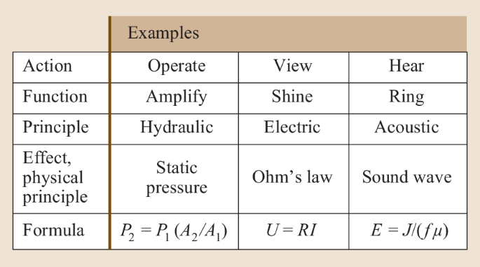
Heuristic approach to the product development process: the five stages of solution finding at the concept stage
-
8.
There should be complete documentation of the state of development.


7.2.2 Improving Error Recognition
Strictly speaking, a formal FMEA carried out with conventional forms [16.78] will be incomplete, since there is no suitable inspection of completeness. This affects the applicability of methodologies and passive error detection. Some ways of improving error recognition rates include:
-
1.
Drawing upon the experience of the FMEA participants
-
2.
Including other specialists
-
3.
Improving knowledge of or becoming acquainted with the product to be analyzed
-
4.
Integrating customer-oriented departments and the customers themselves
-
5.
Recording mistakes and experiences in databases and analyzing them
-
6.
Studying the product history (test reports, complaint reports, etc.)
-
7.
Concurrently applying heuristic support tools (e. g., Goldfire, Invention Machine, Boston).
7.2.3 Including All Secondary Fields of Development
A FMEA focuses only on hardware—not documentation, services, software logistics, test programs, manufacturing methods, production plants, and machines. Measurement and checking facilities, experimental setups, and devices are not covered by a FMEA, even though they could be sources of many errors. This situation can only be improved by including these new fields.
7.3 Procedure
The procedure used to identify the risks during the lifetime of a product, from the first design concept to product use, is always the same, regardless of the product size: it is the same for a small product such as a plug-in contact (Fig. 16.60) or a large technical system such as a machine tool (Fig. 16.61).


Small product: plug-in contact (source: ABB, Baden)


Large product: machine tool (source: A. Breiing, Mikron, Biel)
7.4 Description of the Project
7.4.1 Nomination of the FMEA Moderator
The moderator is nominated with the agreement of the relevant project manager.
7.4.2 Putting Together the FMEA Team
The team (Table 16.14) is put together by the project manager with the agreement of the FMEA moderator. The visibility of the team within the organization is important (Table 16.14). Each department should contribute at least one continuous FMEA team member.
7.4.2.1 Structuring Functions
In FMEA, a functional analysis of the investigated product is performed, implying that functional modules or submodules must be specified. This may be achieved using a hierarchical functional diagram (Fig. 16.62) or a a process-orientated diagram (Fig. 16.63), for example.


Example of the hierarchical functional structure of an autoclave door [16.89]


7.4.2.2 Filling Out the FMEA Form
7.4.2.2.1 Column 1
This column lists all possible sources of error, as shown in Table 16.15. Because errors can occur even during the early stages of product development, but particularly during idea generation and when determining the market performance profile, the corresponding entities must be entered into this column (the first block). Sources of error can also occur during the development phase (second block), during market launch (third block), and (especially) during the usage phase up to product disposal (fourth block).
7.4.2.2.2 Columns 2–4
These columns are filled in upon analyzing all possible potential failures. Examples of potential failures are listed below.
7.4.2.2.3 Possible Errors During the Planning Stage
-
The concept for a new product cannot be realized due to physical, chemical, biological, ethical, legal, or cultural constraints or restrictions
-
The concept has already been realized by competitors
-
The concept is protected by competitors through patents, petty patents, and/or design patents
-
There is no market potential and/or no market gap available
-
The time is not ripe
-
No foe image available or not relevant enough (for military development)
-
Materials used in the product are scarce
-
No sustainable environment
7.4.2.2.4 Possible Errors During the Development Process
-
Internal functions from a function analysis (hierarchical and/or process functional structure)
-
External functions from a use analysis
-
Assembly of the product structure
-
Assembly/disassembly:
-
Assembly/disassembly operation
-
Assembly/disassembly regulations
-
Utilities (e. g., oil for the removal of bearings)
-
Assembly/disassembly devices
-
Control and/or measuring devices (e. g., torque wrench)
-
Additional means (e. g., hoisting devices)
-
-
Components from the product structure and/or parts list
-
Manufacturing:
-
Manufacturing processes (e. g., lapping)
-
Manufacturing operations (for manual manufacturing, e. g., deburring)
-
Manufacturing regulations
-
Manufacturing means and devices (e. g., drilling patterns)
-
Auxiliary manufacturing requirements (e. g., coolant)
-
Control and measuring devices (e. g., calipers).
-
The outer function takes into account the imperfect behavior of users (i. e., humans) during the life of the product. This must be included in the FMEA. The user is a component of the system; (s)he influences all of the processes, from idea generation through development and usage until the end of the product's life cycle. The user can cause failures and errors at any stage. The available use analysis (Table 16.16), which covers all product life cycle stages [16.88], can be used to account for all possible sources of error during assembly, maintenance, and repair (Table 16.15, fourth block).
In order to identify these potential sources of error systematically, the FMEA is expanded through the incorporation of the use analysis. These entities can then be taken from the tabulated record of man–machine interfaces.
Moreover, each part, assembly, and product has technical documentation that must be checked for errors.
7.4.2.2.5 Possible Errors Within the Technical Documentation
It is important to check the:
-
Manufacturing documents (drawings and lists)
-
Documents for assembly/disassembly (e. g., instruction sheets)
-
Calculation documents, such as:
-
Load assumptions
-
Verification of strength
-
Verification of deformation
-
Verification of stability (e. g., buckling, bending, stability)
-
-
Balances, such as:
-
Balance of performance
-
Balance of weight
-
Positions of the centers of gravity
-
Balance of the moments of inertia
-
Balance of temperature
-
Balance of coolant
-
-
Documents such as:
-
Manufacturing documents
-
Instruction sheets
-
Instructions for maintenance and service
-
The spare-part catalog.
-
7.4.2.2.6 Possible Errors During Market Launch
-
Storage:
-
Activities
-
Apparatus (e. g., bearing block)
-
Racks, halls, stacks (e. g., storage rooms with air conditioning)
-
-
Transport:
-
Activities
-
Apparatus (e. g., lifting gear)
-
Means of transportation (e. g., overhead crane)
-
-
Mounting:
-
Activities
-
Mounting regulations and instructions
-
Apparatus (e. g., lifting gear)
-
Measuring and test equipment (e. g., theodolite)
-
-
Initial operation:
-
Activities and testing in accordance with the:
Instruction manual (Initial Setup chapter)
Checklist
User handbook
Maintenance instructions.
-
7.4.2.2.7 Possible Errors During the Use Stage and Decommissioning
-
Initial operation:
-
Activities in accordance with the:
Instruction manual (Initial Setup chapter)
Checklist
Maintenance history
Document
-
-
Operation:
-
Activities in accordance with the:
Instruction manual
User handbook
-
-
Maintenance:
-
Activities and testing in accordance with the:
Instruction manual
User handbook
Service documentation
Maintenance history (e. g., exhaust emissions document for an automobile)
-
-
Service:
-
Activities and testing in accordance with the:
Instruction manual
User handbook
Service manual and spare-part catalog
Logistics documents (e. g., global workshop catalog).
-
7.4.2.2.8 Column 5
The status of each failure measure and each test procedure that is currently used is entered here. These entries are used to reduce the causes of failure in column 4 and to detect possible sources of error.
7.4.2.2.9 Columns 6–10
These columns are used to calculate the risk priority number (RPZ).
Before deciding on the troubleshooting actions that are to be taken, it is very important to obtain an economic perspective on the consequences of those actions. When the FMEA is extended by including a cost calculation, the form will include an additional column that lists values of K, the probable cost of an error.
The RPZ values in column 10 are calculated via
where A is the probability that the failure will occur, which takes the following values:
-
1
Unlikely
-
2
Very low
-
3
Low
-
4
Medium
-
5
High
-
6
Very high.
B is the impact of that failure on the customer, which takes the following values:
-
1
Customer does not notice the consequences
-
2
Insignificant inconvenience to the customer
-
3
Minor inconvenience to the customer
-
4
Significant inconvenience to the customer
-
5
Irritation of the customer
-
6
Possible loss of the customer.
E is the probability of detecting the failure, which takes the following values:
-
1
Very high
-
2
High
-
3
Medium
-
4
Low
-
5
Very low
-
6
Unlikely.
Finally, K is the probable cost of the failure, which takes the following values:
-
1
No or negligible increase in costs
-
2
Minor additional costs
-
3
Moderate additional costs
-
4
High additional costs
-
5
Extremely high additional costs
-
6
Costs are not budgeted for.
Instead of values ranging from 1 to 6, a value range of 1–10 can also be applied, although this is only reasonable if detailed knowledge is available (e. g., from the FMEA at the end of the product development process).
A RPZ value in the range 1296–10000 is considered to be unacceptably high; the range 256–1295 corresponds to medium RPZ; and a RPZ value in the range 1–255 is low. In practice, the threshold RPZ value below which a failure is ignored because it is not profitable to address it can be anywhere between 81 and 625.
7.4.2.2.10 Column 11
The troubleshooting actions that should be performed in the case of an error are entered into this column.
7.4.2.2.11 Columns 12–17
If any of the recommended troubleshooting actions listed in column 11 are performed, those actions are described in column 12 and the RPZ value is recalculated (yielding RPZ*) and listed in columns 13–17. Values of RPZ* listed in column 17 are calculated via
Here, K* is the probable cost of implementing the measures required to avoid or minimize a probable error. Both K and K* have the same range of risk factors. Values of RPZ* are categorized in a similar manner to those of RPZ, meaning that the measures are accepted if RPZ* is below approximately 81–625. If RPZ* is higher than RPZ, the measures applied to avoid or to minimize the error should be reconsidered.
7.5 Further Use of FMEA Results
Several competing solutions or alternatives are available during the concept and sketching phases. In order to identify the best solution, a ranking procedure is carried out. If the ranking procedure takes risk into account, it is reasonable to use the sum of the RPZ or RPZ* values for a particular solution to calculate the risk associated with that solution.
The relationship between acceptance, risk, and weighting is shown in Fig. 16.64.


Relationship between acceptance, risk, and evaluation
8 Bioindustrial Design: Challenges and Vision
Nature did not invent the wheel because it did not need the wheel: the main methods by which organisms move—flying, swimming, diving, running, and gliding—have been perfected over the course of millions of years of continuous (and ongoing) evolution. Mankind’s technical achievements pale in comparison to those of nature. Think tanks aimed at promoting technological development (which often ends in a dead-end street) are wisely drawing upon natural phenomena, implying that biotechnology (bionics) will be one of the main preoccupations of future engineers.
For instance, an international oil company is investigating hydrodynamic molds for lowering giant submerged tankers into shallow, calm depths to shield them from destructive conditions at the surface of the water (the interface between two media). Our own experiences underwater suggest that man-made vessels (even the latest submarines) have nonoptimal designs, as they leave kilometer-long white trails behind them in the semisubmerged state due to poor hydrodynamics. In contrast, orcas and belugas (for example) do not create large water waves when semisubmerged; they glide in the exact same manner as when they are fully submerged. This demonstrates that is it possible to further optimize the design and construction of propellers. Here, as in other comparisons, nature puts the engineering world in the shade.
Even the pressure equalization processes used by the largest mammals in the world—whales—during rapid submerging and surfacing are yet to be studied in detail and imitated in technology. Another water-based example: no complex technical device would survive unscathed the rapid vertical immersion experienced by waterfowl hunting food, nor the rapid change in media that occurs when waterfowl resurface.
The shape of the manta ray has long been held up by aircraft manufacturers as the ideal silhouette for a passenger airplane. Indeed, investigations of the manta ray by Hugo Junkers in the early twentieth century inspired him to design wing-only airplanes. In 1920, he broke new ground with the development of the Junkers D-2500: an (almost) wing-only airplane in which passengers sat in cabins located in the front sections of the wings! In the US, the wing-only concept has been applied in Northrop's B1 and B2 bombers.
In the construction industry too, nature serves as a role model for design and construction. For instance, termite structures—with their ventilation systems that allow the termites to survive low external temperatures unharmed and their fermentation fields that provide a ready supply of food—are essentially giant skyscrapers with approximately 1000 floors. The human equivalent of such a skyscraper would be 3000 m high!
The famous industrial designer Luigi Colani was introduced by the biologist Ernst Haeckel to the miraculous world of microscopic lime structures: architectural inspirations that have been developing in the depths of the oceans for eons. The vast majority of the world’s oceans is unexplored, which raises the question of the benefits of space research, given that the survival of mankind depends more on the careful treatment of our oceans that cover 70% of the Earth’s surface. Unfortunately, the’s extensive lectures and seminars on Bauhaus new beginnings at the Hochschule für Bildende Künste Berlin (later the Academy of Fine Arts and the University of the Arts) could not be realized at that time. Many years later, it should be noted that among the cheerful trilogy of colorful cubes, pyramids, and spheres laid down by Kandinsky, only the cube is left, and was often taught as Bauhaus style in universities and used by leading design teams. The new forms are orthogonal, the materials steel and glass, and the color gray.
German engineering sciences are world leading in many technical fields, but German design will probably never again reach the level of design and color delivered by the Bauhaus in Weimar in the early 1930s, where a colorful group of young, brilliant, international creatives gathered around Walter Gropius to turn conventional petty bourgeois design on its head. Wassily Kandinsky, a Russian artist, designed the ultimate visualization of the Bauhaus approach—a brightly colored logo for the school, to act as a goal and a legacy. However, the novel methods espoused by the Bauhaus were deemed too un-German by the Nazis striving for power and were thus forbidden, causing the intellectual founders of the school to become scattered around the world. After World War II, incomprehensibly, only the cube from Kandinsky’s triple form (cube, pyramid, and sphere) was adopted and cultivated by German designers after World War II, prompting a new—false—identity to be attributed to the true universal Bauhaus design philosophy. Bauhaus became associated with squares and cubes, with steel and glass, with gray. Therefore, only 33% of the original Bauhaus principle has survived. This falsification of the power of shape and color has become the backbone of German design. The corresponding design philosophy can be observed, for example, in the sharp-edged forms of sanitary ceramics and fittings.
However, not all supporters of the old Bauhaus followed suit; for instance, the author—an aerodynamicist and aircraft builder—returned to design to represent the original Bauhaus philosophy with technical competence and steadfastness. The idea of going back to go forward, which the author considers to be crucial to enhancing German design, has only partly been adopted by German industry. That said, the original Bauhaus philosophy has often been applied in other countries, and has led to spectacular new developments (e. g., in the design of sports cars; see Figs. 16.65 and 16.66). From the Design Center in Milan, the author is orchestrating the creation of think tanks aimed at encouraging a better Bauhaus design philosophy and demonstrating the tradition of Bauhaus design around the world, in line with the motto [16.90, 16.91, 16.92, 16.93, 16.94, 16.95, 16.96]: long live the original Bauhaus!


Futuristic sports car design by L. Colani


Design of a Ferrari sports car from 1989 by L. Colani
References
K. Ehrlenspiel: Integrierte Produktentwicklung: Denkabläufe, Methodeneinsatz, Zusammenarbeit, 4th edn. (Hanser, München 2009), in German
K. Roth: Konstruieren mit Konstruktionskatalogen: Konstruktionslehre, 3rd edn. (Springer, Berlin, Heidelberg 2001), in German
G. Pahl, W. Beitz, J. Feldhusen, K.-H. Grote: Konstruktionslehre, 8th edn. (Springer, Berlin, Heidelberg 2013), in German
F. Kramer: Innovative Produktpolitik (Springer, Berlin, Heidelberg 1988), in German
W. Rodenacker: Methodisches Konstruieren, 4th edn. (Springer, Berlin, Heidelberg 1991), in German
R. Koller: Konstruktionslehre für den Maschinenbau, 4th edn. (Springer, Berlin, Heidelberg 1998), in German
VDI: VDI 2221: Methodik zum Entwickeln und Konstruieren technischer Systeme und Produkte (VDI, Düsseldorf 1993), in German
G. Pahl, W. Beitz, J. Feldhusen, K.-H. Grote: Konstruktionslehre, 7th edn. (Springer, Berlin, Heidelberg 2007), in German
K.-H. Grote, J. Feldhusen (Eds.): Dubbel: Taschenbuch für den Maschinenbau, 24th edn. (Springer, Berlin, Heidelberg 2014), in German
H. Petra: Systematik, Erweiterung und Einschränkung von Lastausgleichslösungen für Standgetriebe mit zwei Leistungswegen, Dissertation (TU München, München 1981), in German
DIN: DIN EN 1325: Value Management (Beuth, Berlin 2014), in German
DIN: Sachmerkmale, DIN 4000 – Anwendung in der Praxis (Beuth, Berlin 2006), in German
DIN: DIN 4000 (z. Zt. mit Entwürfen 163 Teile): Sachmerkmal-Leisten [für Norm- und Konstruktionsteile] (Beuth, Berlin 2006), in German
D. Krauser: Methodik zur Merkmalbeschreibung technischer Gegenstände (Beuth, Berlin 1986), in German
H. Czichos, M. Hennecke: Hütte – Das Ingenieurwissen, 34th edn. (Springer, Berlin, Heidelberg 2012), in German
H. Holliger-Uebersax: Handbuch der allgemeinen Morphologie, 4th edn. (MIZ, Zürich 1980), in German
J. Müller: Grundlagen der systematischen Heuristik (Dietz, Berlin 1970), in German
H.G. Schmidt: Heuristische Methoden als Hilfen zur Entscheidungsfindung beim Konzipieren technischer Produkte (TU Berlin, Berlin 1980), in German
V. Krick: An Introduction to Engineering and Engineering Design, 2nd edn. (Wiley, New York 1969)
R.K. Penny: Principles of engineering design, Postgrad. Med. J. 46, 344–349 (1970)
W.F. Daenzer: Systems Engineering, 6th edn. (Industrielle Organisation, Zürich 1989)
F. Zwicky: Entdecken, Erfinden, Forschen im morphologischen Weltbild, 2nd edn. (Baeschlin, Glarus 1989), in German
H. Seeger: Industrie-Designs (Expert, Grafenau 1983), in German
H. Hertel: Biologie und Technik (Krausskopf, Mainz 1963), in German
P. Kerz: Konstruktionselemente und -prinzipien in Natur und Technik, Konstruktion 39, 474–478 (1987), in German
P. Kerz: Natürliche und technische Konstruktionen in Sandwichbauweise, Konstruktion 40, 41–47 (1988), in German
P. Kerz: Zugbeanspruchte Konstruktionen in Natur und Technik, Konstruktion 40, 277–284 (1988), in German
W. Kroy: Abbau von Kreativitätshemmungen in Organisationen. In: Personal-Management in der industriellen Forschung und Entwicklung, ed. by M.E. Domsch (Heymanns, Köln 1984), in German
VDI: VDI 2225 Blatt 1 und 2: Technisch-wirtschaftliches Konstruieren (VDI, Düsseldorf 1998), in German
C. Zangemeister: Nutzwertanalyse in der Systemtechnik, 4th edn. (Wittemann, München 1976), in German
R. Kühnpast: Das System der selbsthelfenden Lösungen in der maschinenbaulichen Konstruktion, Dissertation (TH Darmstadt, Darmstadt 1968), in German
K.-H. Habig: Verschleiß und Härte von Werkstoffen (Hanser, München 1980), in German
VDI: VDI 2242 Blatt 1 und 2: Konstruieren ergonomiegerechter Erzeugnisse (VDI, Düsseldorf 1986), in German; Current draft: VDI 2242:2016-06
I. Klöcker: Produktgestaltung (Springer, Berlin, Heidelberg 1981), in German
VDI: VDI 2243 Blatt 1: Recyclingorientierte Produktentwicklung (VDI, Düsseldorf 2002), in German
H. Meyer: Recyclingorientierte Produktgestaltung (VDI, Düsseldorf 1983), in German
M. Pourshirazi: Recycling und Werkstoffsubstitution bei technischen Produkten als Beitrag zur Ressourcenschonung (TU Berlin, Berlin 1987), in German
R.-D. Weege: Recyclinggerechtes Konstruieren (VDI, Düsseldorf 1981), in German
VDI: VDI 2222: Methodisches Entwickeln von Lösungsprinzipien (VDI, Düsseldorf 1997), in German
F.J. Gierse: Funktionen und Funktionsstrukturen, zentrale Werkzeuge der Wertanalyse, VDI-Berichte, Vol. 849 (VDI, Düsseldorf 1990), in German
V. Hubka: Theorie Technischer Systeme: Grundlagen einer wissenschaftlichen Konstruktionslehre, 2nd edn. (Springer, Berlin, Heidelberg 1984), in German
F. Hansen: Konstruktionssystematik: Grundlagen für eine allgemeine Konstruktionslehre, 2nd edn. (VEB Verlag Technik, Berlin 1965), in German
J. Rugenstein (Ed.): Arbeitsblätter Konstruktionstechnik (Technische Hochschule Magdeburg, Magdeburg 1979), in German
F. Engelmann: Produktplanung und Produktentwicklung in kleinen und mittleren Unternehmen (Shaker, Aachen 1999), in German
Novespace: Parabolic Flight Campaign with A300 ZERO-G User’s Manual, 5th edn. (Novespace, Paris 1999)
R. Bjärnemo: Evaluation and Decision Techniques in the Engineering Design Process (Heurista, Zürich 1991)
A.F. Osborn: Applied Imagination—Principles and Procedures of Creative Thinking (Scribner, New York 1957)
J.O. Nriagu, J.M. Pacyna: Quantitative assessment of worldwide contamination of air, water and soils by trace metals, Nature 333, 134–149 (1988)
T.E. Graedel, B.R. Allenby: Design for Environment (Prentice Hall, New York 1998)
T.E. Graedel: Streamlined Life-Cycle Assessment (Prentice Hall, New York 1998)
W. Leontief: Input-Output Economics, 2nd edn. (Oxford Univ. Press, Oxford 1986)
C. Hendrickson, A. Horvath, S. Joshi, L. Lave: Economic input-output models for life-cycle assessment, Environ. Sci. Technol. 13(4), 184A–191A (1998)
R. Miller, P. Blair: Input-output analysis: foundations and extensions. In: Environmental Input-Output Analysis (Prentice Hall, New York 1985) pp. 236–260, Chap. 7
S. Joshi: Product environmental life-cycle assessment using input-output techniques, J. Ind. Ecol. 3(2/3), 95–120 (2000)
S. Suh, G. Huppes: Methods for life cycle inventory of a product, J. Cleaner Prod. 13, 687–697 (2005)
Environmental Protection Agency: EPA TRI 2015 Data release web page, http://www.epa.gov/tri/ (2015)
V. Smil: Energies—An Illustrated Guide to the Biosphere and Civilization (MIT Press, Cambridge 1999)
K.J. Martchek, E.S. Fisher, D. Klocko: Alcoa’s worldwide life cycle information initiative, SAE Conf. Proc. 339, 121–126 (1998)
P.F. Chapman, F. Roberts: Metals Resources and Energy (Butterworth-Heinemann, London 1983)
E. Williams, R. Ayres, H. Heller: The 1.7 kg microchip: energy and chemical use in the production of semiconductors, Environ. Sci. Technol. 36(24), 5504–5510 (2002)
J. Dahmus, T. Gutowski: An environmental analysis of machining. In: ASME Int. Mech. Eng. Congr, ed. by L. Yao (ASME, New York 2004)
S. Dalquist, T. Gutowski: Life cycle analysis of conventional manufacturing techniques: sand casting. In: ASME Int. Mech. Eng. Congr, ed. by L. Yao (ASME, New York 2004)
J. Sherman, B. Chin, P.D.T. Huibers, R. Garcia-Valls, T.A. Hatton: Solvent replacement for green processing, Environ. Health Persp. 106(Suppl. 1), 253–271 (1998)
V.M. Thomas, T.G. Spiro: The U.S. dioxin inventory: Are there missing sources?, Environ. Sci. Technol. 30(2), 82A–85A (1996)
A. Grubler: Technology and Global Change (Cambridge Univ. Press, Cambridge 1998)
Passivhaus Institut: Passipedia – Die Passivhaus-Wissensdatenbank, https://passipedia.de/ (2017), in German
A. Graf: Das Passivhaus – Wohnen ohne Heizung (Callwey, München 2000), in German
Informations-Gemeinschaft Passivhaus Deutschland: Aktiv für mehr Behaglichkeit: Das Passivhaus, 9th edn. (IG Passivhaus Deutschland, Darmstadt 2016), in German
Passivhaus Institut: http://www.passiv.de
Bundesverband der Energie- und Wasserwirtschaft e. V.: „Wie heizt Deutschland?“ – BDEW-Studie zum Heizungsmarkt (BDEW, Berlin 2015)
Techem Energy Services: Energiekennwerte 2016. Eine Studie von Techem zum Wärme- und Energieverbrauch in Mehrfamilienhäusern (Techem, Eschborn 2016), in German
R. Kuehr, E. Williams (Eds.): Computers and the Environment: Understanding and Managing their Impacts (Kluwer Academic, Dordrecht 2004)
Microelectronics, Computer Technology Corporation: Life Cycle Assessment of a Computer Workstation, Report HVE-059-094 (MCC, Austin 1994)
K. Kawamoto, J. Koomey, B. Nordman, A. Meier: Electricity used by office equipment and network equipment in the U.S. In: 2000 Summer Study on Energy Efficiency in Buildings (ACEEE, Washington 2000)
E. Williams: Environmental impacts in the production of personal computers. In: Computers and the Environment: Understanding and Managing Their Impacts, ed. by R. Kuehr, E. Williams (Kluwer Academic, Dordrecht 2004) pp. 41–72
Environmental Protection Agency: EPA egrid 2004 (EPA, Washington 1998)
W.S. Jevons: The Coal Question: An Inquiry Concerning the Progress of the Nation, and the Probable Exhaustion of our Coal-mines, Reprints of Economic Classics (Kelley, Fairfield 1906)
DIN: DIN EN 60812: Fehlzustandsart- und -auswirkungsanalyse (FMEA) (Beuth, Berlin 2006), in German; Current draft: DIN EN 60812:2015-08
Department of Defense: Procedures for Performing a Failure Mode, Effects and Criticality Analysis (FMECA), MIL Std., Vol. 1629A (Department of Defense, Washington 1980)
P. Conrad, P.E. Hedderich: Navy Proactive Maintenance (US Navy, Washington 2000)
N. Berens: Anwendung der FMEA in Entwicklung und Produktion (Verlag Moderne Industrie, Landsberg 1989), in German
C.H. Kepner, B.B. Tregoe: Entscheidungen vorbereiten und richtig treffen (Verlag Moderne Industrie, Landsberg 1988), in German
M. Schubert: FMEA – Fehlermöglichkeits- und Einflußanalyse (Deutsche Gesellschaft für Qualität, Frankfurt 1993), in German
A. Breiing: Die FMEA in sinnvoller Form für Investitionsgüter (Institut für Mechanische Systeme, ETH Zürich, Zürich 2003), in German
A. Breiing: The evaluators influence on the results of evaluation. In: MCE 2000, Neukirchen (2000)
A. Breiing: Who evaluate the evaluators? In: Int. Conf. Comput. Integr. Manuf., Zakopane (2001)
A. Breiing, R. Knosala: Bewerten Technischer Systeme (Springer, Berlin, Heidelberg 1997), in German
A. Breiing: Vertiefungsvorlesung Produkte-Design (Institut für Mechanische Systeme, ETH Zürich, Zürich 2000), in German
A. Breiing, M. Flemming: Theorie und Methoden des Konstruierens (Springer, Berlin, Heidelberg 1993), in German
L. Colani, A. Fujimoto (Eds.): Part 1—Designing Tomorrow: Car Styling, Tomorrow, Vol. 23 (Sanei Shobo, Tokyo 1978)
L. Colani, A. Fujimoto (Eds.): Part 2—For a Brighter Tomorrow: Car Styling, Tomorrow, Vol. 34 (Sanei Shobo, Tokyo 1981)
L. Colani, A. Fujimoto (Eds.): Part 3—Bio-design of Tomorrow: Car Styling, Tomorrow, Vol. 46 (Sanei Shobo, Tokyo 1984)
A. Bangert: Colani—Fifty Years of Designing the Future (Thames Hudson, London 2004)
A. Bangert: Colani—Form Follows Nature (Bangert, Schopfheim 2009)
L. Colani, A. Bangert: Colani—The Art of Shaping the Future (Bangert, Schopfheim 2004)
L. Colani: Bio-Industrie-Design: Herausforderungen und Visionen. In: Dubbel – Taschenbuch für den Maschinenbau, 24th edn., ed. by K.-H. Grote, J. Feldhusen (Vieweg, Wiesbaden 2014), in German
Author information
Authors and Affiliations
Corresponding author
Editor information
Editors and Affiliations
Rights and permissions
Copyright information
© 2021 Springer Nature Switzerland AG
About this chapter
Cite this chapter
Engelmann, F., Breiing, A., Gutowski, T. (2021). Engineering Design. In: Grote, KH., Hefazi, H. (eds) Springer Handbook of Mechanical Engineering. Springer Handbooks. Springer, Cham. https://doi.org/10.1007/978-3-030-47035-7_16
Download citation
DOI: https://doi.org/10.1007/978-3-030-47035-7_16
Publisher Name: Springer, Cham
Print ISBN: 978-3-030-47034-0
Online ISBN: 978-3-030-47035-7
eBook Packages: EngineeringEngineering (R0)