
Abstract
The aim of this monograph chapter is to introduce green facades and green roofs in the Czech Republic. In the beginning, the history and development of green roofs and facades have been outlined; the type of green roofs and ways of facade greening, structures and systemic solutions, protection against slide and drainage have been described; and the functions and benefits of green roofs and facades have been estimated. Next part discusses measurements of the vapor from green roofs and the cooling effect. Finally, the zero carbon facility has been described—example from Brno (Czech Republic)—The Open Gardens. The results from online monitoring have been shown, and the roof and urban heat islands have been discussed.
Access provided by Autonomous University of Puebla. Download chapter PDF
Keywords
- Roof sheathing
- Climbing plants
- Succulent
- Vertical gardens
- Zero carbon
- Cooling effect
- Evaporation
- Water cycle
- Urban heat island
- Green infrastructure
1 Introduction
The roof protects the under-roof spaces against weather. The basic function is to protect the construction and the indoor environment from precipitation water, to protect and secure the condition of the indoor environment. The roof can be operationally used if it is designed for that purpose [1].
Roofs that are not designed for that purpose fulfill only the basic function. They are expected only for the movement of instructed persons on the roof, who is ensuring the control and maintenance of the roof itself and its supplementary constructions.
If the roofs are designed for operational use, they can be used as roof terraces, roof gardens, car parks, heliports, and more. It requires the adequate design of the structure and construction of the roof and special drainage solutions. Moreover, it requires the solutions of the security measures, because the so-called uninstructed persons move on the roofs.
As ČSN 73 1901 Roof Design—Basic provisions stated, the roofs must meet basic requirements such as mechanical resistance and stability, fire resistance, protection of the indoor environment from noise. Hygiene, health, and the environment protection (exclusion of occurrence of molds, water leakage and exclusion of damp of building structures, and subsequent deterioration of the indoor environment by moisture) should be followed. Besides the energy saving and thermal protection, but also the aesthetic requirements for the appearance of the roof must be met. The bearing structure of the roof should be designed in such a way that its durability is the same as that of the building construction. Reliability is ensured by adequate technical solutions and maintenance of roofs. The system of inspections, controls, maintenance, and renewal of the roof, including drainage elements, must be determined by the designer.
One of the possibilities of building roofing is a green roof, a roof with a vegetation cover, where the upper layer of the roof consists of soil and vegetation in the form of mosses, herbs, grasses, shrubs or trees. These types of roofs are called green, greening roofs, vegetation roofs, grassed roofs, roof gardens, etc. It can also fulfill the ecological function except for the representative, mainly nowadays.
There are many reasons for increasing green areas, especially in cities where the construction of buildings displaced practically all the greenery only into parks. Green roofs may become an almost integral part of roofs of new buildings in urban areas just because of air purification from airborne particles and temperature reduction, as well as the increase of humidity in the roof surroundings and partial water retention, especially during summer months [2].
The green roof may not be just a matter of flat roofs, i.e., with a slope of up to 5°, as it may seem, but it is possible to green the roofs with a slope of up to 60°. In slopes of 20°, the substrate must always be secured against landslide, in the case of smaller slopes with respect to substrate coherence. However, the roof with a slope of 2°–5° is considered optimal [3].
The concept of a green facade (vertical gardens, vertical walls, green walls, or living walls) is used to grow plants located in a vertical plane so as to cover walls, pillars, or columns of buildings.
2 History and Development of Green Roofs and Facades
The tradition of green roofs can be found both in the Nordic countries, e.g., Iceland, USA, Scandinavian countries and in regions with very different climatic conditions, e.g., Tanzania. They are mostly without the possibility to be walked on, and their meaning was purely practical, i.e., thermal insulation and heat or cold accumulation. In the harsh climate of Iceland, houses with the walls and the non-supporting part of the roof from two to three layers of peat turf were built. This provided adequate protection against heat leakage, and these houses did not need to be heated, because the necessary heat was produced by the residents of the house [4].
The first preserved mentions about green roofs have been found in the Middle East during excavations of Nineveh (Assyria and Babylon areas, north of today’s Iraq) from the period of the reign of King Solomon (929–917 BC. N. L.) [3].
However, the world’s second wonder—the Semiramis Hanging Gardens in Babylon—which were probably founded in the sixth century BC, is better known. It was a terraced roof garden with a square ground plan. The weight of the soil, not to mention the trees that grew out of it, was an extraordinary load. Roof gardens were supported by colonnades—arches supported by stone columns. Admirable is mainly the support and irrigation system. A sophisticated irrigation system with spiral pumps powered by human power was used here. The water was further distributed by a system of channels to vegetation. The water was pumped from the nearby river Euphrates [5].
The roof gardens have spread from the Middle East to Southern Europe during the period of the Greek and Roman Empires. During this period, the rich Roman burghers of the higher classes, the so-called patricians, built these gardens on their houses and palaces to put their wealth on display. Because poorer people cannot afford them, they placed pots on the terraces [3].
The construction of roof gardens almost stopped for 400 years after the demise of the West Roman Empire [4]. The green roofs were built in the Byzantine Empire again in the palaces in the Middle Ages. Their popularity grew in France and especially in Italy since the mid-eleventh century, but the biggest boom occurred during the Renaissance, thanks to patrons for example in Rome, Venice, and Verona. In the seventeenth and eighteenth centuries, the roof gardens extend into German and English cities. There is also theoretical work on this issue, and in some Italian urban states, the regulations on the construction of green roofs are adopted [3].
An important milestone not only for the structure of green roofs, but also for the entire construction industry, was the year 1867, when Joseph Monier patented his invention—reinforced concrete [3]. The building physical properties of reinforced concrete allowed the development of green roofs. The new material helped to solve a number of existing problems. Roof gardens still had high demands on the static solution, but the reinforced concrete ensured the permanent strength and stability of the building and extended the service life of all building elements [6].
Since the beginning of the last century, the theme of green roofs has been dealt with, for example, by the Swiss architect Le Corbusier, who published five points of modern architecture already in 1926. The second point is about roof gardens on flat roofs. Le Corbusier emphasized that green roofs increase the green area of the city, and their soil protects the top floor of the house from moisture [7].
Green roofs are more often used due to the development of building chemistry and plastics after the Second World War. More and more significant buildings are being designed with roof green after 1950 [6].
Green roof gardens are created not only as a protection against external influences but also as a means of ecology in the 70s and 80s in the 20th century in the German-speaking countries. German experts deserved their research on the development of new materials for greening roofs, such as the protective layers against root penetration, or drainage prefabricated from polystyrene foam. They also developed the principles for establishing green roofs, even for greening of roofs with the slope. The companies specialized in green roofs are established in parallel with the research and they become a regular part of designing new objects or renovations. Since 1993, a program for the implementation of roof gardens for agriculture, which was ended after the economic crisis in the year 2008, worked in Russia (http://ccisf.org/cci/) [3].
The green roofs are popular in Germany or Australia. The Canadian city of Toronto has adopted a regulation for mandatory green roofs in large commercial, administrative, and residential buildings already in 2009, wrote Guardian. France decided that each new building in the commercial zone would have to have a “green” roof in the spring of 2015. The developer will be able to choose whether to place photovoltaic panels on the roof or to cover the roof with plants [8].
The green roofs, or rather the roof gardens, begin to appear in the Czech Republic in the second half of the nineteenth century. The first sign is the roof of the castle stable in Lipník nad Bečvou, which is still functional. It has undergone two large reconstructions—the first in 1911 and the second not long ago—in 2005–2006 [3].
Functional and no problem realization of the green roof is allowed by the development of hydro-isolation technologies. Increased interest in green roofs can be seen here after 1989, when it is more often possible to get acquainted with the practical experience of building green roofs from abroad. Ecological educational centers, which also focus on the issue of green roofs, are established in our country.
Climbing plants are one of the possibilities of greening the facades; their history dates back to ancient times. Olšan [9] states that the oldest iconographic sources about climbing plants on the walls are wall paintings in tombs. Grapevine and ivy were used to climb various pergolas along the paths or were planted on sunny walls in ancient Greece and Rome. In the gardens of the late Middle Ages (France, England, Netherlands, and Central Europe), there were plants tied to support constructions on the walls in the gardens. These were fruit trees most often. This type of plant cultivation was referred to as the Mauerspaliere in Germany.
Olšan [9] states that interest in the use of climbing plants in the composition declined at the time of Baroque. Climbing trees were planted to buildings and elements of only a small garden architecture. For example, fences, which could be “embroidered” by climbing plants, were formed along the lower part of the high green walls and hedges. The assortment was not too wide; woodbine, roses, honeysuckles, ivy, and peas were mainly used. Since the first half of the nineteenth century (periods of neoclassicism and romanticism), climbing trees have found greater use in natural landscape gardens and parks. The variety Rosa x francofurtana became the dominant growing climbing variety, which spread rapidly throughout Central Europe. This plant was mainly used to climb the arcades and was later pushed by new varieties of climbing roses. To this period, ivy, woodbine, and Aristolochia can be included. The second half of the nineteenth century was greatly influenced by the theoretical work of German garden architects and practitioners of Gustav Meyer and Hermann Jäger.
Vertical gardens are most often associated with the French botanist, scientist, and art designer Patrick Blanc (1953). He became famous for the vertical green walls called le mur végétal or vertical garden (plant wall). The green wall of the Hotel Pershing Hall, Paris, from 2001, is the first big realization of the Blanc system. Until then, it was applied only to relatively small areas. A total number of 320 plant species were used to create this over thirty meters high natural tapestry with a variable look. It is a living green composition that connects all six floors of the building [10].
It is possible to consider as a predecessor of vertical gardens in the Czech Republic a rock created more than 40 years ago in the Arboretum of Mendel University in Brno (see Fig. 3.1). Vertical outdoor gardens are rather rare in our country.

(Source Kotásková)
A predecessor of vertical gardens—a vertical rock in the Arboretum of Mendel University
3 Types of Green Roofs
Standard ČSN 73 1901—Roofs design—the basic provisions distinguish only two groups of green roofs—classical growing layering with intensive greenery and economical growing formation with extensive planting. However, in practice and also in professional literature Čermáková and Mužíková [3] a finer division is used. According to the degree of necessary gardening interventions and the origin of the plant community, we distinguish biotope, intensive, semi-intensive, and extensive green roofs. In the design of the roof, the climatic conditions of the site should be taken into account.
3.1 Roof with Intensive Planting
We speak about intensive planting when the depth of the substrate is at least 300 mm, but the exact distribution is different in the literature. The formation can be up to 1000 mm in depth, and it allows planting not only of lawns, perennials, grasses, bulbs, annuals, but also of shrubs or trees with flat root systems [6].
This type of greening is, therefore, more demanding for maintenance and also for the purchase price. Intensive green roofs are designed with such vegetation, which requires gardening maintenance to keep its character. If this maintenance is neglected, the planting vegetation will die and, as a consequence of this, there will be a significant reduction of the value of the entire roof covering—deterioration of aesthetic perception, reduction in retention capacity, erosion of the substrate, and associated loss of proper function of the roof. It is recommended to provide these roofs with a subsurface irrigation system.
This type of roof can only be used on flat roofs. The advantage of this type of greening is that it is a real roof garden with the possibility of using it for relaxation (see Fig. 3.2). Deeper layers of substrate and appropriate vegetation enhance the function of the green roof. Greater loads are to be expected; the weight of these roofs when they are fully saturated with water can reach 300 kg/m2 or more [3].

(Source Kotásková)
Roof with intensive planting
3.2 Roof with Extensive Planting
Extensive greening differs from the previous type by a thinner layer of the substrate (approximately 60–200 mm). Thanks to it a smaller surface weight should be taken into account. This does not place such high demands on the support construction of the roof. The surface weight in the fully saturated state is in the range of 60–300 kg/m2 [3]. This type of roof is usually not intended for a walk, and there is no need for artificial irrigation. The disadvantage is the limitation of the choice of vegetation, because the plants growing on these roofs must be able to withstand difficult conditions such as drought or wetting. That is why we can often see succulents on these roofs, such as stonecrops, houseleeks, or xerophilous grasses and perennials (see Fig. 3.3). The care lies only in the occasional removal of undesirable air raids. This type is also suitable for reconstruction.

(Source Kotásková)
Roof with extensive planting
3.3 Roof with Semi-intensive Planting
This is the transition between intensive and extensive planting. The thickness of the substrate is between 150 and 300 mm. Planted species usually do not require much care, except for ensuring sufficient moisture, especially after the realization of planting. This type of roof is usually designed for grassy surfaces suitable for walking. Therefore, in our conditions, semi-intensive greenery requires minimal maintenance and especially sufficient moisture and sufficient thickness of the substrate.
3.4 Biotope Roof
Biotope green roofs represent an approach in which the roof layering is not planted, but it is gradually populated by the air raid plant species from the immediate vicinity. It is a roof with extensive greenery of natural biotopes. These roofs are left largely without care. It is the most ecological and economical type of planting [11].
4 Ways of Facade Greening
Pejchal [12] lists systems connected with loose soil and not connected with loose soil (vertical gardens).
4.1 Systems Connected with Loose Soil
Facades with systems connected with loose soil are those where the plants are planted directly into the soil close to the facade. Climbing plants can be found among herbs—both annuals and perennials, as well as among trees. Self-climbing and also plants not able to self-climb (liana) are used, which belong to a group of climbing plants.
Plants, which are not able to climb themselves, require support for their growth. Some of them are spinning around their support (e.g., Lonicera caprifolium, Wisteria sinensis, Thunbergia alata, Humulus lupulus), another are tendril plants—these use tendrils to grip to support (Vitis vinifera, Parthenocissus vitacea, Clematis vitalba, Lathyrus odoratus, Cobaea scandens) or buckling, which are attached by side shoots (Rosa canina), spines (Rubus fruticosus), thorns (Lycium barbarum) or leaves (Tropaeolum majus) [12].
Burian [13] reports that self-climbing plants have a relatively narrow assortment. We distinguish the rooting ones (Hedera, Campsis, Hydrangea, Schizophragma) and tendrils (Parthenocissus) (see Fig. 3.4).

(Source Kotásková)
Facade system connected with loose soil—self-climbing
4.2 Systems Not Connected with Loose Soil
Systems that are not connected with loose soil are the new way of greening the facades. They are further divided into the shelf, modular, and planar systems. Vertical garden growing systems can be simply divided into two groups, systems using the substrate and without using the substrate.
Shelf systems have pre-hanging containers or troughs on the wall, in which the plants are grown.
Modular systems allow, with the help of prefabricated elements hanged on the support construction of the wall, to be covered all over its surface. The supporting construction is mostly composed of hanging profiles that are directly screwed to the facade and cassettes made of metal or plastic mesh with growing substrate or substrates slabs made of modified foam substances or mineral fibers.
Planar structures have vegetation systems made of materials supplied with “standard meters”. Plants can be planted after they are installed on the wall. The support construction consists of supporting pillars with horizontal and vertical bars. These supporting pillars are either anchored directly to the wall of the building or in a certain distance to the ground. Textile systems based on the principle of hydroponics are then attached to the construction. They usually have two layers of synthetic high-absorbent fabric (felt) that are attached to a non-absorbent plastic support plate. Plants are planted into them.
Textile and substrate systems represent a compromise between cassette systems (more reliable but heavy) and textile systems (less reliable but light). In textile and substrate systems, a classical soil substrate, moss, mineral substrate (lava), or stone (mineral) wool may appear. The substrate is covered with non-woven fabric with slots or circular gaps for planting on its surface. In terms of overall construction and fastening, it is largely identified with textile systems, the difference is mainly in the substrate, which is placed in the slots, circular holes, or pockets [14].
For these types of facades, irrigation must be provided. The most reliable method is a drip irrigation system where water, including the necessary nutrients, is distributed through hoses into the whole system. It is started up either by humidity sensors or timers.
5 Structure of Membrane Roofing of Green Roofs
The design of the structure is based on the supposed use of the roof, the slope of the roof plane, and the limit load of the substructure. Typical is the structure of the green roof with the classical order of the layers where the damp course is placed above the thermal insulation. It consists of layers that in their combination ensure correct function of the chosen solution. They are:
-
supporting structure;
-
gradient layer;
-
thermal insulation;
-
waterproof membrane;
-
protection barrier;
-
drainage layer;
-
filter membrane;
-
vegetative layer;
-
vegetation.
Some layers may be omitted in some cases, or one layer may fulfill multiple functions at the same time (e.g., hydrophilic mineral wools combine substrate, dry area, and hydro-accumulation layers into one product).
5.1 Supporting Structure
The bearing layers may be formed by an area-covering bearing structure or a structure of rod and area-covering elements. For a flat roof, the bearing structure is made up of a ceiling structure above the last floor.
5.2 The Gradient Layer
The gradient layer is formed from embankments, light concrete, concrete, plastic, or mineral fiber components. It can also be formed with a bearing structure. The gradient layer of the thermal insulating materials can fill the thermal insulating layer at the same time.
5.3 Thermal Insulation
For the design of the thermal insulation layer of the green roof, it is important that the thermal parameters of the entire roof structure including the vegetation layer meet the normative requirements (see ČSN 730540-2: Thermal protection of buildings. Requirements) [15].
Thermally insulating layers are formed from foam glass thermal insulation boards, extruded polystyrene, as well as porous or gap materials with limited water absorption capacity.
5.4 Waterproof Membrane
The damp proofing is the most important layer of the roof structure, as it ensures that the water does not penetrate into the roof and under roof structures. In the case of vegetation roofs, the quality of the used material and the design is even more important, because the hydro-isolation will be difficulty accessible for inspection and repair. In the event of a leak, it is practically impossible to locate exactly the site (the water can flow a few meters from the perforation site) where the failure occurred and the whole vegetation formation has to be removed, what is very costly. The design of damp proofing is based on the ČSN P 73 0606—Damp proofing of the buildings, where the minimum slope for dewatering elements is 1.75% and for safe drainage 3–5%. Checking the waterproofness of the damp proofing is carried out both visually and by flood testing, before the other layers are applied, in order to remove possible deficiencies [3].
Around the permeable structures and exposed areas, it is advisable to design gravel bands or tiled pavement. For correct function, it is important to make perfect bonds, including overhangs, the use of foils with resistance to root growth. It is also needed to pay attention to the compatibility of damp proofing with other layers of the roof structure; otherwise, we need to put the separating layer between them [16].
Stabilization of damp proofing against wind suction can be done by mechanical anchorage, bonding, stabilizing layer, or a combination of these methods. Stabilization by imposed load in the case of green roofs is ensured by the weight of the vegetation layer and at the edges of the roofs where the largest wind suction occurs, the imposed load is done by, for example, the belt of aggregate with fraction 8/16 with the minimum thickness of 40 mm or the fraction 16/32 with a minimum thickness of 50 mm, or concrete products.
The materials used for the damp proofing of vegetation roofs are the most frequently modified bitumen felt and hydro-insulating foils. Oxidized bitumen belts can only be used in case of specially sealed joints, and a separate protective layer with root growth resistance must be installed. Long-term tests have shown that different plants have been rooted in bitumen isolates, because microorganisms living on roots can decompose these substances. Root growth resistance is of modified bitumen belts ensured by adding of additives or copper sheet in this case [3].
5.5 Protection Barrier
The coating serves primarily to protect the damp proofing against its mechanical damage. However, it can also fulfill root growth resistance function and assists in the accumulation of less water. Its function can also be taken over by a dry area of profiled foil with overlaps (at least 250 mm) and glued joints. However, this solution should be verified by the producer.
Non-woven fabrics (minimum plan weight 300 g/m2), cement or concrete screed, hydrophilic mineral wool, as well as sheets and foils used in the dry area are used as the coating. When using a cement-based screed, it is advisable to limit its absorption capacity and to ensure leaching of carbonate by using a damp course spattle or sealing coat. The cement screed should have a thickness of at least 30 mm, and it must be separated from the damp proofing by a separation and dilatation layer (e.g., PE foil) [3].
5.6 Drainage Layer
This layer is used to drain excess water to the roof drains to prevent the substrate from overflowing. Plant roots need to absorb oxygen for plant nutrition, what is impossible, when it is immersed in water and plants die. However, the dry area may also serve to accumulate water in the case of long-lasting droughts, and in this case, it is called the dry—hydro-accumulation layer. It provides a minimum amount of water in the vegetative layer for growing plants and reduces the flow of rainwater in short intense rainfall.
The materials used for this layer may be loose (Liapor, brick recyclate) or profiled foils or boards. For loose materials, the ability to retain water (15–20%) is desirable, so these materials must have predominantly open voids and varied texture. The use of natural aggregates is therefore inappropriate. Profiled sheets and profiled polystyrene boards entrap the water for a season without rain and can hold 5–10 l of water per m2 of their surface. Perforated foils are also available on the market, where the perforation on the top of the protrusion also serves to aerate the root system of the plants [3, 6].
5.7 Filter Membrane
The filter bed (also separating) serves to prevent the dry area from clogging through the washed substrate elements. The filter fabric is in some cases directly embedded directly on the profiled foil, which can reduce the time needed for placing. For flat roofs with a substrate thickness of up to 250 mm, fabrics with a basis weight of 100–200 g/m2 are sufficient. The filter bed is laid at all points of contact with the substrate with other materials.
5.8 Vegetative Layers
The roof substrate can be understood as a substitute for common soil for the living space of the plant community. For the greening of the roofs, it is not an ideal solution to use only soil, especially clay, because of its worse composition and higher weight. If we want to use the topsoil that was detached before the building of the house, it is advantageous to lighten it with mineral fillers or sand. Mineral fillers include broken Liapor, pumice stone, broken porous bricks. It is recommended to lighten the topsoil with 30–60 volume percent of mineral fillers with a fraction of 0–16 mm. The choice of the substrate and its thickness is then chosen according to the composition of the planned vegetation and the bearing capacity of the substructure [3].
6 Systemic Solutions for Green Roofs
6.1 Urbanscape
Urbanscape is a system suitable for extensive green roofs. It is a composition of the layers, where the substantial layer is made of a product called Green Roll, which substitutes the natural substrate. It is an optimal basis for plant growth. It is a mineral wool material that produces a stable felt that is highly absorbent and can retain more water than traditional or even modified substrates [11]. The retention of the same amount of water requires a much thinner layer than the substrate. The material has a low bulk density, so it is statically (it does not burden the roof too much) also a good solution for roof reconstruction.
So the urbanscape system includes a pre-cultivated green vegetation layer with stonecrops (Sedum), a Green Roll mineral wool, a plastic drainage film that drains excess water during the rainy season, while ventilates the plant root system and a protective foil that protects the damp proofing against rooting.
6.2 Vedaflor Systems
The system offers three variants of green roofs—for extensive but also for semi-intensive and intensive planting. Variants differ in the thickness of the professionally tested ecological substrate [11]. The thinnest layer of the substrate allows growth of stonecrops; the medium thickness is able to ensure the growth of grasses and herbs; and at the greatest thickness, it is possible to design roof gardens.
The damp course is made of bituminous melting tapes or plastic foils. Furthermore, the system includes fleece with retention and protective function, a filtering function, and a drainage function [11].
6.3 Isover System
The hydrophilic mineral wool is the main layer of the green roof like in the urbanscape system, which partially substitutes the layer of the substrate depending on the thickness of the vegetative layers. These are hydro-accumulating boards that significantly reduce the weight of the vegetative layers while it ensures the retention capacity of the roof. Plants can be rooted in these plates without any problems.
For roofs with low extensive vegetation, the thickness of boards 50 mm and substrate 30–100 mm is recommended. It is also necessary to use the drainage foil as protection against overflow, to increase the drainage capacity of the drainage profiled foil. Roofs with semi-intensive layering have a vegetative layer made up of a 100–200 mm substrate and 100 mm hydro-accumulation plates. Roofs with intensive planting have a total vegetative layer thickness of 300–1000 mm. Mineral wool boards should form up to half of it. The sufficient thickness of the mineral wool layer is 100–300 mm [11].
7 Protection Against Slide and Drainage
It is not usually necessary to provide the substrate against the landslide at a slope of up to 20°. It depends not only on the slope but also on substrate thickness, length of the sloping roof area and substrate coherence. If the vegetation is not completely rooted, it could slide at 15°. One of the measures to prevent the landslide is to place the beams under the membrane roofing. The beams should have round edges to prevent damages of damp proofing on the sharp edges. Another way is a solution with different fabrics, plastic beams, or plastic or steel mats. Using the entire skidproof system is possible [17].
8 Draining of the Green Roofs
There are two ways to get the water on the green roof—firstly is it meteoric water (rainfall and snowfall, eventually hail) and secondly the water through irrigation. Excessive water, it means this, which is not entrap by substrate or hydro-accumulation layer, must be removed from the membrane roofing.
The draining of the green roof may be outside and inside the building. The external draining is usually designed by the sloping to the edge of the floor plan equipped with a hanging gutter (see Fig. 3.5).

(Source Kotásková)
Edge of the roof with semi-intensive planting
The internal draining is solved by troughs or perforated pipes that are plugged into the inlets or directly with inlets. A perfect connection of the damp proofing to the roof inlet must be ensured. It is necessary to separate the inlet from the vegetation, for example, with a roof adapter, so that it does not glaze. Suitable treatment is to pour aggregate around and separation from vegetation with filter geotextiles.
In order to ensure draining of the meteoric water at the sloping roofs in a sufficient degree, it is usually necessary to lay along the eaves edge around 300 mm wide strip of aggregate with the drain pipe. The eaves edge must be provided with a sufficiently rigid edge profile to provide shear forces from the layers of aggregate and soil (see Fig. 3.6).

([95] modified by Kotásková)
Structure of the green roof and solution of the edge of roof
9 Functions and Benefits of Green Roofs and Facades
Together with the basic functions that each roof has to meet, the green roof has many specific functions related to environmental and microclimate improvement, and its aesthetic character is inimitable:
-
create, on the same site on which the building stands, new areas of green and outdoor living space;
-
create new green areas for rest and recreation;
-
reduce the share of concrete and paved areas;
-
improve the look of cities and landscapes;
-
enhance the living and working environment.
Within a landscape in villages or in adjacent areas of the cities, it is possible by the use of green roofs to partially hide the building, which may not be recognizable from the surrounding terrain from certain points of view. For even better results, we can inspire with houses that have vegetation not only on the roof, but they can also have the walls land up with the soil [4].
Green roofs function [16]:
-
reduces the spreading rate of open areas and the share of paved areas;
-
produces oxygen and binds carbon dioxide;
-
filters particles of dust and dirt out of the air and absorbs pollutants;
-
prevents overheating of roofs and thus swirling of the dust (see Fig. 3.7).
Fig. 3.7 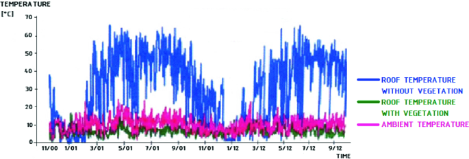
([6] modified by Kotásková)
Course of the temperatures of the roofs with and without vegetation depending on the surrounding temperature

The measurement showed that at a temperature of 30–35 °C there is the maximum temperature of 20 °C at a substrate depth of 100 mm. In winter, at night temperatures around −10 °C, the temperature between 0 and −1 °C was measured in the substrate at a depth of 50 mm [6].
-
reduce temperature fluctuations caused by rotating of day and night;
-
reduce air humidity fluctuations.
Advantages of green roofs:
-
have almost an unlimited lifetime in the case of a professional design;
-
have a thermal insulation effect;
-
protect the attic from intensive solar heat in the summer;
-
acts as insulation from a sound;
-
are considered to be non-flammable;
-
slow down effluent of meteoric water, thereby reducing the use of the public sewer.
As Minke state out below [16]:
-
spread the aromatic scent;
-
create an environment for insects;
-
are aesthetic, induce a positive state of mind and a sense of relaxation in man.
9.1 Influence on the Microclimate of the Building
Large concrete and asphalt areas have a high accumulation of heat and mostly low reflectance, thus contributing to the increase of temperature (the so-called thermal island), which has complex impacts on the environment in which we live. The difference between the temperature in the center and the outskirts of the city may be up to 11 °C in the summer months [2]. Increased temperature causes raising of the dust and pollutants from the ground. They then fly through the air and cause more difficult breathing and increased dustiness in habitable rooms, which is also undesirable even for cleaning. Dust particles and higher air temperatures are the reason of up to 15% decrease of sunshine and over 30–100% increased the occurrence of fog [2]. These aspects also cause a greater occurrence of storms and contribute significantly to smog situations [3].
Vegetation growing on green roofs limits thermal extremes by heat exchange between the plant and the surrounding environment until the equilibrium state is reached. The energy required to convert one liter of water into steam is approximately 2.2 kJ [16].
The layering of green roofs influences the microclimate in buildings, both by regulating the temperature, as described above, and by increasing the humidity around the roof. The increasing of the moisture is realized by transpiration of plants, evaporation from the soil, and evaporation of condensed dew on the surface of the plants. These aspects depend on the composition of the vegetation, where the ideal is a vertical layering of vegetation, dense green with large areas of leaves [3].
9.2 Protective Function
The green on the roof causes less temperature fluctuations, which lead to the smaller extensibility of the materials and thus increase the service life compared to flat roofs without vegetation. A great advantage is the protection against UV radiation, which degrades the majority of materials, and this again contributes to extending the service life of the entire roof. Therefore, we cannot forget the fact, that it is possible to use damp proofing with lower resistance to UV radiation (the damp proofing is exposed to its impacts only during the construction before it is covered with other layers). On the other hand, it is necessary to apply damp proofing with a certificate against the growth of roots. The vegetation layering also partly works as an element, which reduces the risk of flooding and sewerage network loads, because the drainage from these roofs is reduced up to 50% and it happens gradually, what is appropriate during the torrential rains.
9.3 The Function of the Green Facade
Its function is not only aesthetic, but has many other benefits that improve the environment of the residents, such as the greening of the places where is not ordinary greenery or where it was destroyed by the building. Every piece of greenery, especially the irrigated one, brings people a fresh feeling, extra in the summer months when the concrete surfaces in the cities are hot.
Green facades create a thermal insulation of the cladding of the building. It protects against cold in winter, and on the contrary, it prevents heat radiation and thus overheating of rooms. They reduce the dustiness in the surroundings, like the green roofs. The vegetation on the facade also absorbs the noise from the surrounding area.
The substantial positive is the social aspect of the placing of vertical gardens. In the places, where the facades were installed, the vandalism was greatly reduced and the safety of the place overall improved. It is obvious that the spaces created by these facades affect the behavior of people. People naturally respect this unusual part of nature. I think, it is good to place vertical greenery even in places where there is not only a problem with the built-up area but also a problem with disrespect and ignorance of the residents in the environment. The facades could serve to the natural upbringing of children and to the respect for nature in general. Thanks to the ability to green the city, the vertical garden can be one of the many sub-tools to achieve sustainable urban development [18].
Negatives, on the other hand, include the concentration of insects in the leaf stand, the effect of sticky roots on the facade. For example, such an ivy has more aggressive roots and can disrupt the facade. In disputed cases, for example, part of the tenants is for, and part is against, it is advisable to choose climbing plants that wrap around the prepared support tendrils that need support for their growth. Today, there are a lot of systems on the market, which can help to fix these plants [19].
9.4 Cooling Functions of Trees and Green Roofs in the Urban Climate
Almost every city on earth is warmer than the surrounding area by 1–4 °C and acts as a “thermal island” [20]. The effect of the thermal island of cities lies primarily on the high portion of the built-up area on a small proportion of vegetation. Buildings, asphalt, concrete, and other dark and hard surfaces absorb solar radiation, what causes that these surfaces are about 10–20 °C warmer than the surroundings and subsequently released the heat to the atmosphere [21,22,23,24,25,26,27]. In addition, these surfaces quickly drain water into the sewerage system and do not allow its gradual evaporation. Thereby, it would naturally cool down the microclimate of the city.
The vegetation responds to solar radiation by evaporating of the water and thus by cooling the surface of the leaves. The energy required to convert liquid to steam is referred as specific evaporative heat. The amount of 2450 kJ of energy is needed to evaporate one kilogram of water at 20 °C. This energy is consumpted from the incidental solar radiation and thus cannot participate in heating the surface and then radiating the heat to the surroundings. Another way of reducing the negative effects of the effect of the city’s thermal island lies in the absorption of water in plants—this water very well accumulates the incidental solar radiation. Photosynthesis also plays an important role because it consumes 2.83 kJ of energy for the production of each glucose molecule. The very specific physical and chemical properties of water are keys in terms of cooling function, in particular, high specific evaporation heat of water and very high specific thermal capacity (three times greater than most other materials such as iron and aluminum rocks). These extraordinary characteristics of water are caused particularly as a result of the presence of so-called hydrogen bonds. Atoms bound in the water molecule are not arranged linearly (in one line), but the chemical bonds between the atoms make an angle of approximately 105°. The mentioned nonlinearity of the molecule owes the water molecule for its polarity, for the existence of hydrogen bond, also called hydrogen bridges.
Vegetation elements in cities gain increasing importance as climate changes, mainly because of their ability to eliminate the negative effects of global warming. The building of green roofs, facades, and planting trees in cities are a key adaptation strategy against the negative effects of heat islands, reinforced by the influences of global warming [28, 29]. Many cities have developed heat island strategies, and green roofs and facades are their integral part as it is, for example by Vienna [30], Melbourne [23, 31, 32], Kuala Lumpur, et al. Singapore, and Hong Kong [26], Athens [25]. The vulnerability of European cities due to climate change is convincingly evaluated by Tapia [28]. According to data from 2006, green roofs had the largest representation in Germany, with a green roof of 10% of all buildings [33].
Green (vegetative) surfaces in cities can play an essential role in the water (and thus energy) balance of the urban landscape only if they are sufficiently represented. While today we can quite exactly quantify the increased costs of their construction related to buildings (residential, administrative, and industrial), the quantification of their environmental functions (hydrological is one of the most important) has not yet been examined in the Czech Republic in detail. The most common studies related to the cooling effect of green roofs and facades logically come from warm areas such as the Mediterranean [34, 35] or tropics [36], but studies from Central European are no exception [37].
10 Measurement of the Vapor from Green Roof—The Case Study from Brno
A case study focused on measuring the quantity and dynamics of vapor from green roof was carried out in a vegetative period of 2017 in the Open Garden of the Foundation Partnerství Brno. The purpose of the case study was to determine what part of the energy of the incoming solar radiation was used for green roof evaporation. The evaporation was determined based on Bowen’s ratio.
10.1 Materials and Methods
The measurements were realized on a green roof located in the center of Brno. It is an intensive green roof with the area 463 m2. Typical species for extensive planting were used for greening (e.g. Dianthus carthusianorum, Festuca rubra commutata, Festuca ovina, Festuca glauca, Stipa pennata, Silene vulgaris, Lychnis viscaria, Knautia arvensis, Sedum acre, Agrimonia eupatoria, and Bromus erectus). The substrate was composed of 70% of topsoil with the addition of sand (fraction 0–2 mm) in a ratio of 3: 1 and 30% of drainage particles (milled mineral fiber, slag, milled brick recycled −0 to 16 mm).
A meteorological station was installed on the green roof to measure climate variables. The following variables were observed within the meteorological station: wind speed and direction, global radiation, precipitation, temperature and soil humidity. The temperature and air humidity sensors were installed at the height of 0.5 and 2 m above the ground for the purposes of Bowen ratio calculation. A bearing construction and an instrumental box with accessories are the part of the station. The data from all sensors were continuously stored in the data logger memory at ten-minute intervals.
The following variables entered into the calculation of the green roof vapor using Bowen ratio: global radiation (W/m2), air temperature at 2 m above ground (C°), air temperature at 0.5 ms above ground (C°), air humidity in 2 m above ground (%), and air humidity at 0.5 m above ground (%). All calculations were realized for data at hourly intervals. The pressure of saturated vapor at a certain temperature was calculated in the first phase of the calculation, and it was calculated separately for temperatures at heights of 0.5 and 2 m above ground level—formula 1 according to Allen et al. [38]:
where
- e s :
-
saturation vapor pressure at temperature T (kPa)
- T :
-
temperature (°C)
In the next step (see formula 2, [38]), the actual vapor pressure at the heights of 0.5 and 2 m above the ground was calculated using the previous calculation (3.1) and the relative humidity of the air:
where:
- e :
-
the real pressure of the vapor (kPa)
- e s :
-
the pressure of the saturation vapor at a certain temperature (kPa)
- Rh:
-
relative humidity of the air (%).
Subsequently, Bowen’s ratio was calculated according to the following formula (formula. 3, [39]):
where
- β :
-
Bowen ratio
- γ :
-
psychrometric constant = 0.066 kPa °C−1
- T 2m :
-
temperature at height of 2 m (°C)
- T0.5m:
-
temperature at height of 0.5 m (°C)
- e 2m :
-
vapor pressure at height of 2 m (kPa).
- e 0.5m :
-
vapor pressure at height of 0.5 m (kPa)
In the last step, the evaporation was calculated according to the following formula (formula 4, [39]):
where
- E :
-
the evaporation of the lawn in (mm m2 h−1)
- L :
-
latent evaporation heat of water = 2450 kJ kg
- Rn:
-
net radiation calculated as 5% of the global radiation
- β :
-
Bowen ratio.
10.2 Results and Discussion
There is evident very intensive vapor from Fig. 3.8. It shows a gradually increasing trend of daily vapor values, reaching the peak in June (median 4.3 mm/m2). This trend has gradually decreased since July to the minimum values reached in October (median 1.2 mm/m2). Maximum values of daily vapors occurred in June and August with a value of 6 mm/m2. On the contrary, the minimum daily values were reached in September and October with a value of 0.2 mm/m2. The above-described trend of the quantity of vapor reflects the potential evapotranspiration, respectively, evaporative requirements of the atmosphere (the values of potential evapotranspiration are not presented in the chapter, but they were calculated) and at the same time the water supply in the soil.

(Source own investigation)
Daily vapor sums of 1 m2 of a green roof in individual months of measurement
Table 3.1 shows that most of the solar radiation was supplied in June, on the contrary, the least amount in the month of October. The green roof has evaporated most of the water in June (125 l * m−2), on the contrary, the least in October (34.4 l * m−2). The lawn has evaporated 570.2 l * m−2 during the monitored period, what is significantly higher than the sum of the vertical precipitation over the period (422.4 l * m−2). The horizontal precipitation and probably also the supplies of soil water accumulated from the winter period also play a significant role from the point of view of the quantity of vapor from the green roof. The amount of 46–69% of the energy supplied by the solar radiation has been consumed on the vapor of the lawn. The values calculated by us correspond to the values obtained by other authors (e.g. [40]). According to Minke [41], in some cases, there is the possibility of 90% usage of solar radiation energy for the vapor.
The evaporation of vegetation of green roofs or facades is a significant measurable indicator, which is a key component of both water and energy (especially thermal) balances of green surfaces in the urban ecosystem. Most scientific studies are focused on the thermal balance of green roofs and facades or its components. Favorable influence on the cooling of the external surroundings is well documented [42], whether using thermal imaging [43,44,45] or direct measurements of temperature, both on the surface and at different distances from it [35, 37, 46,47,48].
Different simulation models and programs are often used [49,50,51], such as EnergyPlus, ENVI-met or DesignBuilder [52,53,54]. Gros et al. [55] have developed new indicators of the cooling output of green elements in the cities—energy performance index (EPI) and ambient temperature mitigation index (ATMI).
Favorable influence of green strata on the thermal regime inside the building is proven [36, 56,57,58], and it consists of the reduction of temperature extremes (fluctuation) due to thermal insulation properties, reduction of summer temperatures, and increase of winter temperatures [59,60,61,62], which in result leads to energy savings for both heating and air-conditioning [63]. Measurement and comparison of energy consumption dedicates to maintain appropriate indoor temperature for buildings with different types of roofs, including green roofs [64]. The cost–benefit analyzes were also carried out for this purpose [65, 66]. Also durability analyzes show that green roofs and facades are profitable in the long-term point of [67,68,69].
While the thermal regime is described in many studies in great details, the water regime of green roofs and facades is neglected in the current literature. Only a few studies also deal with the measurement of the air humidity above green surfaces [34, 70], with drainage of water from the torrential precipitation [71] or the transpiration of lianas of green facades [72]. Evapotranspiration is one of the most important causes of the cooling effect of green roofs and facades [29, 57, 71, 73], but only very few studies are focused on the direct measurement [74,75,76], which mainly use lysimeters [77].
However, green roofs and facades are considered a suitable contribution not only to the improvement of microclimatic conditions [34, 78,79,80,81], but also the aesthetic quality of buildings and their surroundings [82], decrease of noise [46], dust reduction and also air quality [83] and as such positively affect the health of the population [84,85,86] and are positively perceived by them [82].
The practice of using green roofs and facades in the Czech Republic is largely unsatisfactory. Vegetative (green) roofs as the most common application are perceived as a complicated solution associated with increased investment costs, difficult maintenance, and unclear overall effect. A multidisciplinary approach (team of plant breeders and climatic context, construction professionals, experts for evaluation of ecological contexts, etc.) combining theoretical reasoning and models with several levels of experimental methods and practical verifications is necessary for the clear identification of barriers defending to larger extension of green roofs and facades and searching of practically usable solutions. Due to the lack of technically relevant information for designers and investors, it could otherwise happen that fans of green roofs and facades will overestimate the thermal insulation effects and cooling effects and their opponents will underestimate it.
10.3 Concluding Remarks
Achieved results confirmed the importance of green roofs in the urban environment. The green roof of The Foundation Partnerství Brno was able to evaporate 1–6 mm/m2 of water during the day. The process of evaporation depends on the actual conditions of potential evapotranspiration and the amount of available soil water. Monthly sums of vapor of green roof ranged from 34 to 125 mm/m2, and 46–69% of the solar energy input was consumed during evaporation. If this energy was not draining away by vapor, it would be used to heat the city surface.
11 Zero Carbon Facility—Case Study of Environmental Partnership, Brno
11.1 Urban Context
Combating climate change in urban areas will always remain a complex combination of various tools: technical and natural infrastructure, soft political, planning, educational, and social, behavioral priorities or instruments. Often its basis could be just the recovering, interlinking, and re-packaging of existing city activities scattered in traditional sectors, such as greening public spaces or buildings, rainwater management, river restorations, public awareness, and emergency policies into one comprehensive climate adaptation strategy and implementation plan [87,88,89].
In recent decades, there has been no single blueprint or solution and sharing best practice seems to be the most efficient process for increasing the resilience of urban areas toward increasing weather extremes. Measuring the impact of various climate adaptations/mitigation tools, including their economic feasibility should be an integral part of their implementation (see, for instance, [90], or conclusions from the last global conferences in Rotterdam or Capetown [91, 92].
11.2 The Property of Open Gardens—A Case Study
The 15,000 m2 large complex of the educational Open Gardens (see Figs. 3.9 and 3.10), the property of the Environmental Partnership Foundation in Brno, became a model zero carbon facility with energy and water balance proven by 2–5 years long continuous measuring. Data online are available on http://www.otevrenazahrada.cz/energie [93].

(Source Nadace Partnerství)
Aerial photograph of The Open Gardens

(Source Nadace Partnerství)
Open Gardens map—distribution of smart technologies
The Open Gardens infrastructure consists of:
-
Historic six-floor building A with minimal environmental improvements—comparative baseline.
-
200 years old four floors (980 m2) administrative building B reconstructed in 2012 into a passive energy standard one with 20 KWp PVE power plant on a flat roof.
-
New three floors (1030 m2) educational and dissemination building C with a green roof and meteorological station on top.
-
Educational part of the garden (4000 m2—including buildings) with nature science interpretation play stations for schools, underground tanks for collection of rainwater from roofs and sidewalks (total storage capacity is about 50 m3), 8 geothermal drills, each 130 m deep, small reed bed water treatment biotope, and with experimental measuring of water sap on 4 maple trees (Mendel University since 2016).
-
Small City Farm with community gardens, bees, animals, and outdoor kitchen with extensive 36 m large green roof (rainwater discharge monitored since January 2018) on remaining 11,000 m2 of garden.
11.3 Monitoring Online
Monitoring of energy and water balance, including indoor and outdoor temperatures, is a baseline for the evaluation of the efficiency of climate adaptation/mitigation tools and also for comparing technological solutions with its natural green infrastructure impact.
For monitoring of the energy and water balance, 70 online meters were installed in Open Garden facility (the system was completed in 2016 with small improvements in 2017). The metering enables to measure not only the consumption/production of electric energy or the use of drinking water but also the energy for heating and cooling the buildings, rainwater discharge from three types of roofs, use of gray water for flushing and watering gardens, etc. Data collected after almost six years of operation of the facility enables us to analyze in detail the functioning of the buildings (used for optimizing facility management), their impact on the microclimate and return on investment of several smart technologies implemented on the foundation property.
11.4 Zero Carbon Energy Performance
Well-insulated buildings (passive energy standard) powered by recuperation and other technologies minimize energy consumption by itself to the level below 20 kW/m2/year. The first year after construction there was typically higher heat energy use (see Fig. 3.11).

(Source Own investigation)
Zero carbon energy performance
Zero carbon impact is multiplied by connecting passive buildings to a geothermal source of energy for heating and cooling. Energy from eight drills of a total length of 905 m is transformed into cooling or heating energy via four heat pumps by using a minimum of electric energy (Seasonal Coefficient of Performance = 5−6) (see Fig. 3.12).

(Source Nadace Partnerství)
Monitoring system showing SCP for the year 2017
This very low amount of additional energy for heating and cooling combined with high efficiency of technology used for tempering two buildings (2000 m2 floor area) enables a very high return on investment. The system of geothermal drills, heat pumps, and related networks distributing energy pays back in only 7 years (annual costs for heating and cooling are 1 EUR/m2/year). Furthermore, given its positive influence on CO2 reduction and replacement of increasing use air-conditioning units, which produce noise and contribute to the urban heat island, the heat pumps using energy from the ground have been proven as the most sustainable and environmentally friendly solution for urban areas.
Additional electrical energy for the offices is partly generated from the 20 kWp PVE located on the roof (produces 20% of the total need), and the rest is purchased from renewable energy provided by a distributor from the grid. The Open Garden facility covers 100% of its electric energy need from renewable sources.
11.5 Roofs and Urban Heat Island
The Open Gardens provide conditions to monitor the impact of various types of roofs and surfaces on the microclimate and to evaluate their potential to be used as climate adaptation elements in the urban areas. See infrared air snap from summer day, 29.8.2016—14:00, air temperature 28 °C, humidity 36% in Fig. 3.13a, b. The rainwater discharge from the roofs runs through flow meters before it is collected into the underground tank for further reuse. The discharge has been monitored online since April 2016 on the intensive green roof (15–25 cm thickness of soil) on the new building C and on the flat roof with a PVE plant on the reconstructed building B, both with the same acreage of 300 m2. Since January 2018, we have measured discharge also from the extensive green roof (36 m2 of Sedum matting on 7 cm thick mineral wool) on the outdoor wooden construction. The composition of species is as follows Sedum sexangulare, Sedum spurium “Fuldaglut”, Sedum reflexum, Stonecrop Angelina, Sedum lydium, Sedum lydium “Glauca,” Sedum kampschaticum, Sedum hybr. “Immergrunchen,” Sedum album, Sedum hispanicum “Minus”, Sedum album coral carpet, Sedum acre.

(Source Mendel University, Brno)
Infrared air snap from summer day, 29.8.2016—14:00, air temperature 28 °C, humidity 36%
A significant water retention capacity of green roofs is apparent from the cumulative data. Even the extensive Sedum mat roof is able to reduce the discharge of rainwater by 10 times. It is evident that the extension of green roofs can significantly moderate peaks in the city sewage system during storms. The positive effect of the green roof on microclimates based on data from Open Gardens monitoring in vegetation season 2017 has been summarized by Svobodová [94]: The green roof is capable of evaporating 1–6 mm/m2 during the day. Monthly sums of evaporation varied between 34 and 125 mm/m2, which translate into 46–69% of solar energy depletion by evaporation. This energy otherwise would contribute to urban overheating. The comparison of discharge from three types of roof is given in Table 3.2.
Another important positive effect of the green roofs is their contribution to the “temperature stability” of the building. In summer, the layer of soil on the roof prevents overheating, and in winter, it improves insulation. See differences in temperatures measured on the surface and 10 cm under the surface in summer (Fig. 3.14a) and winter (Fig. 3.14b).

(Source Own investigation)
a, b Temperatures on the surface and 10 cm under the surface in summer (a) and winter (b)
A higher need of cooling energy used in building B (without a green roof) compared to the neighboring building C with intensive green roof also indicates a positive influence of green roofs on temperatures in the upper floors (see Fig. 3.15).

(Source Nadace Partnerství)
Screenshot from the monitoring dashboard—comparison of energy used for cooling of two passive buildings in 2017: Build B with a normal roof, Build C with an intensive green roof
11.6 Lessons from Water Management in the Open Gardens
The facility was conceptually designed in 2010 with the intention to test technologies for minimizing its ecological footprint. There were no hard data about the retention capacity of the green roofs available, and most of the water management components have been adopted during the operation of the facility based on experience. Water saving taps and toilet flushing systems enable to save 30% of drinking water. Use of rainwater for flushing toilets in building C as well as for watering the gardens enables to save almost 60% of drinking water. The original expectation is that rainwater discharge from the green roof will contribute to the storage significantly, but this was true only in the first two years of operation (2013, 2014) with “normal” distribution of temperatures and precipitations. Dry and hot years 2015–2018 did not allow almost any discharge from the intensive green roof, and all the precipitation capacity was accumulated in the soil and later evaporated through the plants. Thus, the underground storage tank is fed just by rainwater from classic roofs and from paved walkways in the property. It does not provide enough rainwater for the needs of the highly visited and intensively used environmental center and offices (30,000 visitors per year), and it needs to be supported by the underground water pumped from the well (see Fig. 3.16).

(Source Own investigation)
Amount of the water from the pipeline, water from the well and rainwater
The return on investment into the system re-useable rainwater (50 m3 storage capacity, pipe network, pumps, and ultraviolet cleaning technology) is about 10 years.
The obtained data show that in optimizing rainwater management the decision makers should take into account that green roofs have a significant effect on moderating urban heat islands, but they will not contribute by rainwater discharge to water management balance. It is more useful to collect rainwater from solid surfaces and classic roofs wherever possible.
12 Conclusions and Recommendations
The roof with vegetation cover, besides the basic function, which is the protection of the construction and the indoor environment from meteoric water, fulfills many specific functions related to the improvement of the environment. The roof can be representative. It can be used for recreational purposes and at the same time fulfill the ecological function.
The most important potential of green roofs though is their climate adaptation function. They help to moderate urban heat islands and measuring their retention capacity approved that even extensive green roof can significantly cut the peaks of runoff from extreme storm rains.
Increased investment, whether on the load-bearing structure or the layers needed for the planting, will subsequently provide savings of the operating costs. Well-designed layers of green roof significantly increase the durability of the membrane roofing as the vegetation, and vegetative layers protect against the weather effects the damp course of the roof or facade.
Greenery and substrates, especially on the roof, improve thermal insulating and reduce thermal extremes; there is also smaller material expansion and thus the durability, compared to flat roofs without vegetation, increases. A great advantage is a protection against UV radiation, which degrades the majority of materials, what contributes to extending the durability of the entire roof again.
By measuring on a particular green roof and calculations, it was verified that the vegetation reacts to solar radiation by evaporation of water, and thus by cooling of the surrounding environment, which is great benefit especially in the urban environment in mentioned summer months.
References
ČSN 73 1901 (2011) Roof design—basic provisions. ÚNMZ, Prague
Kotásková P, Štěpán J (2016) Green roofs of wooden constructions. In: Building partner 2/2016, pp 27–39. ISSN 1805-5958
Čermáková B, Mužíková R (2009) Green roofs. 1st ed. Praha: Grada, 246 pp. ISBN 978-80-247-1802-6
Frkal L (2007) Houses protected by soil. 1st ed. ERA group, Brno 94 pp. ISBN 978- 80-7366-095-6
Zamarovský V (1990) For the seven wonders of the world. Albatros, Praha, p 253
Šimečková J, Večeřová I (2010) Green roofs—Hope for the future. 1st ed. Union of Planting and Maintenance of Green, Brno, 40 p. Available from www: http://www.zelenestrechy.info/UserFiles/File/szuz_zelene-strechy_indd.pdf
Haas F (1983) Architecture of the 20th century: nationwide textbooks for college students at university, 3rd edn. SPN. Textbooks for universities, Praha
Guardian (2015) France decrees new rooftops must be covered in plants or solar panels [online]. [cit. 2018-03-02]. Available from: https://www.theguardian.com/world/2015/mar/20/france-decrees-new-rooftops-must-be-covered-in-plants-or-solar-panels
Olšan J (2011) History of trelages, pergolas and green walls (Historie treláží, pergol a zelených stěn). In: Green facade (Zelené fasády: odborný jednodenní seminář). Společnost pro zahradní a krajinářskou tvorbu, Praha 152 pp
Růžička V (2011) Beautiful vertical gardens saving homes (Krásné vertikální zahrady zachraňují domy). [online]. [cit. 2016-03-08]. Available from: https://bydleni.idnes.cz/vertikalni-zahrada-0aw-/architektura.aspx?c=A110624_111117_architektura_web
Vrabcová A (2017) Detached house with a green roof project (Návrh rodinného domu se zelenou střechou). Bachelors thesis. Brno, Mendel University
Pejchal M (2011) Plants for “vertical gardens” outdoors. (Rostliny pro “vertikální zahrady” ve venkovním prostoru). In: Green facade (Zelené fasády: odborný jednodenní seminář). Praha: Společnost pro zahradní a krajinářskou tvorbu. 152 p. pp 1–6
Burian S (2011) Use of climbing plants (Využití pnoucích rostlin). In: Green facade (Zelené fasády: odborný jednodenní seminář). Společnost pro zahradní a krajinářskou tvorbu, Praha, 152 p
Přerovská Z (2013) Vertical gargens in exterior and interior (Vertikální zahrady v exteriéru a interiéru). Diploma thesis. Mendel University, Brno
ČSN 73 05 40-2 (20012) Thermal protection of buildings—Part 2: requirements. ÚNMZ, Prague
Minke G (2001) Green Roofs: planning, realization, practice examples. 1st ed. Ostrava: HEL. 92 pp. ISBN 80-86167-17-8
Balík L (2009) About the green roofs (O zelených střechách) [online]. [cit. 2018-05- 06]. Available from: https://www.zelenastrechacz.cz/zelene-strechy
Ulrychová M (2009) Mur vegetal—Patric Blanc [online]. [cit. 2018-03-02]. Available from: http://www.greenlab.cz/cs/clanky/mur-vegetal-patrick-blanc/
Růžička V (2015) Green facades in several ways (Zelené fasády na několik způsobů). [online]. [cit. 2016-04-08]. Available from: https://mujdum.dumabyt.cz/rubriky/zahrada/zelene-fasady-na-nekolik-zpusobu_1954.html
Oke T (1973) City size and the urban heat island. Atmos Environ 7(8):769–779
Taha H, Sailor D, Akbari H (1992) High-albedo materials for the reduction of building cooling energy use [online]. 1992, 17 [cit. 2018-04-10]. doi: 10.2172/7000986. Available from: https://www.osti.gov/biblio/7000986
Forman RTT (2014) Urban ecology. Cambridge University Press, Science of Cities, p 462
Norton BA, Coutts AM, Livesley SJ, Harris RJ, Hunter AM, Williams NSG (2015) Planning for cooler cities: a framework to prioritize green infrastructure to mitigate high temperatures in urban landscapes. Landsc Urban Plan 134:127–138
Krüger EL (2015) Urban heat island and indoor comfort effects in social housing dwellings. Landsc Urban Plan 134:147–156
Varras G, Chiotelli K, Fragaki V, Karras G, Tsantopoulos G (2016) Potentials and prospects for the expansion of green areas on buildings in the metropolitan area of Athens. Acta Hortic 1108:331–337
Aflaki A, Mirnezhad M, Ghaffarianhoseini A, Ghaffarianhoseini A, Omrany H, Wang ZH, Akbari H (2017) Urban heat island mitigation strategies: a state-of-the-art review on Kuala Lumpur, Singapore and Hong Kong. Cities 62:131–145
Dhalluin A, Bozonnet E (2015) Urban heat islands and sensitive building design—a study in some french cities’ context. Sustain Cities Soc 19:292–299
Tapia C, Abajo B, Feliu E, Mendizabal M, Martínez JA, Fernández JG, Laburu T, Lejarazu A (2017) An indicator-basedvulnerability evaluation for European cities. Ecol Ind 78:142–155
Sheweka SM, Mohamed NM (2012) Green facades as a new sustainable approach towards climate change. Energy Proced 18:507–520
Brandenburg Ch, Damyanovic D, Reinwald F, Allex B, Gantner B, Czachs Ch, Morawetz U, Kömle D, Kniepert M (2015) Urban Heat Islands. Strategieplan Wien, Wiener Umweltschutzabteilung—Magistratsabteilung, p 22
Rayner JP, Raynor KJ, Williams NSG (2010) Façade greening: a case study from melbourne. Australia Acta Hort 881:709–713
Murphy SM, Rayner JP, Hall G, Francis J (2016) Growing green: developing industry guidelines for green infrastructure. Acta Hortic 1108:291–296
Köhler M (2006) Long-term vegetation research on two extensive green roofs in Berlin. Urban Habitats 4:3–26
Pérez G, Rincón L, Vila A, González JM, Cabeza LF (2011) Behavior of green façades in mediterranean continental climate. Energy Convers Manag 52:1861–1867
AboElata AAA (2017) Study the vegetation as urban strategy to mitigate the urban heat island in the mega city of Cairo. Process Environ Sci 37:386–395
Sunakorn P, Yimprayoon Ch (2011) Thermal performance of biofacade with natural ventilation in the tropical climate. Process Eng 21:34–41
Martin M, Afshari A, Armstrong PR, Norford LK (2016) A new validation protocol for an urban microclimate model based on temperature measurements in a Central European city. Energy Build 114:38–53
Allen RG, Pereira LS, Raes D, Smith M (1998) Crop evapotranspiration- Guidelines for computing crop water requirements-FAO Irrigation and drainage paper 56. Fao, Rome 300(9):D05109
Duffková R, Kučera, J (2005) Methodology of analysis of water stress of grassland. In: Rožnovský J, Litschmann T (edn) Seminar “Evaporation and evapotranspiration”, Brno, March 23, 2005, ISBN 80-86690-24-5, pp 59–66
Kučera et al (2011) Evapotranspiration of selected types of agricultural and forest stands. In Hydrology of Small Basin 2011
Minke G (2001) Green Roofs: planning, realization, examples from practice. 1st ed. HEL, Ostrava. ISBN 80-86167-17-8
Afshari A (2017) A new model of urban cooling demand and heat island-application to vertical green systems (VGS). Energy and Buildings, in press
Spala A, Bagiorgas HS, Assimakopoulos MN, Kalavrouziotis J, Matthopoulos D, Mihalakakou G (2008) On the green roof system. Selection, state of the art and energy potential investigation of a system installed in an office building in Athens Greece. Renew Energy 33:173–177
Zölch T, Maderspacher J, Wamsler Ch, Pauleit S (2016) Using green infrastructure for urban climate-proofing: an evaluation of the thermal mitigation measures at the micro-scale. Urban Forestry and Urban Greening 20:305–316
Niachou A, Papakonstantinou K, Santamouris M, Tsangrassoulis A, Mihalakakou G (2001) Analysis of the green roof thermal properties and the investigation of its energy performance. Energy Build 33:719–729
Wong NH, Tan AYK, Chen Y, Sekar K, Tan PY, Chan D, Chiang K, Wong NCH (2010) Thermal evaluation of vertical greenery systems for building walls. Build Environ 45:663–672
Cheng CY, Cheung KKS, Chu LM (2010) Thermal performance of a vegetated cladding system on façade walls. Build Environ 45:1779–1787
Perini K, Ottelé M, Fraaij ALA, Haas EM, Raiteri R (2011) Vertical greening systems and the effect on air flow and temperature on the building envelope. Build Environ 46:2287–2294
Wong NH, Tan AYK, Tan PY, Wong NCh (2009) Energy simulation of vertical greenery systems. Energy Build 41:1401–1408
Yuan J, Emura K, Farnham C (2017) Is urban urban albedo or urban green covering more effiective for urban microclimate improvement? A simulation for Osaka. Sustain Cities Soc 32:78–86
Stec WJ, van Paassen AHC, Maziarz A (2005) The modeling of the double skin facade with plants. Energy Build 37:419–427
Larsen SF, Filippin C, Lesino G (2014) Thermal simulation of a double skin façade with plants. Energy Proced 57:1763–1772
Lobaccaro G, Acero JA (2015) Comparative analysis of green actions to improve outdoor thermal comfort within typical urban street canyons. Urban Climate 14:251–267
Feng H, Hewage K (2014) Energy saving performance of green vegetation on LEED certified buildings. Energy Build 75:281–289
Gros A, Bozonnet E, Inard Ch, Musy M (2016) A new performance indicator to assess building and district cooling strategies. Process Engineering 169:117–124
Pons O, Nadal A, Sanye-Mengual E, Llorach-Massana P, Cuervad E, Sanjuan-Delmas D, Muñoze C, Rovira MR (2015) Roofs of the future: rooftop greenhouses to improve building metabolism. Process Eng 123:441–448
Jaffal I, Ouldboukhitine S-E, Belarbi R (2012) A comprehensive study of the impact of green roofs on building energy performance. Renew Energy 43:157–164
Gross G (2012) Effects of different vegetation on the temperature in an urban building environment. Micro-scale numerical experiments. Meteorologische Zeitschrift 21(4):399–412
Koyama T, Yoshinaga M, Maeda K, Yamauchi A (2014) Room temperature reductions in relation to growth traits of kudzu vine (Pueraria lobata): experimental quantification. Ecol Eng 70:217–226
Ballarini I, Corrado V (2012) Analysis of the building energy balance to investigate the effect of thermal insulation in summer conditions. Energy Build 52:168–180
Coma J, Pérez G, Solé C, Castell A, Cabeza LF (2014) New green facades as passive systems for energy savings on buildings. Energy Proced 57:1851–1859
Ip K, Lam M, Miller A (2010) Shading performance of a vertical deciduous climbing plant canopy. Build Environ 45:81–88
Castleton HF, Stovin V, Beck SBM, Davison JB (2010) Green roofs; building energy savings and the potential for retrofit. Energy Build 42:1582–1591
Susca T, Gaffin SR, Dell’Osso GR (2011) Positive effect of vegetation. Urban heat island and green roofs. Environ Pollut 159:2119–2126
Ascione A, Bianco N, de Rossi F, Turni G, Vanoli GP (2013) Green roofs in European climates. Does it have effective solutions for energy savings in air conditioning? Appl Energy 104:845–859
Perini K, Rosasco P (2013) Costebenefit analysis for green façades and living wall systems. Build Environ 70:110–121
Ottelé M, Perini K, Fraaij ALA, Haasa EM, Raiteri R (2011) Comparative life cycle analysis for green façades and living wall systems. Energy Build 43:3419–3429
Bianchini F, Hewage K (2012) How “green” are the green roofs? Lifecycle analysis of green roof materials. Build Environ 48:57–65
Sozer H (2010) Improving energy efficiency through the design of the building envelope. Build Environ 45:2581–2593
Djedjig R, Bozonnet E, Belarbi R (2015) Experimental study of the urban microclimate potential of green roofs and green walls in street canyons. Int J Low-Carbon Technol 10:34–44
Roehr D, Laurenz J (2008) Living skins: environmental benefits of green envelopes in the city context. Trans Ecol Environ 113:149–158
Hoelscher M-T, Nehls T, Jänicke B, Wessolek G (2016) Quantifying cooling effects of facade greening: Shading, transpiration and insulation. Energy Build 114:283–290
Chanampa M, Rivas PV, Ojembarrena JA, Olivieri F (2010) Systems of vegetal façade and green roofs used as a sustainable option in architecture. Des Princ Pract: Int J 4:1–10
Williams NSG, Hughes RE, Jones NM, Bradbury DA, Rayner JP (2010) The performance of native and exotic species for extensive green roofs in Melbourne, Australia. Acta Hort 881:689–696
Onmura S, Matsumoto M, Hokoi S (2001) Study on evaporation cooling effect of roof lawn gardens. Energy Build 33:653–666
Takakura T, Kitade S, Goto E (2000) Cooling effect of greenery cover over a building. Energy Build 31:1–6
Köhler M (2009) Energetic aspects of green roofs. In: Appl R, Ansel W (eds) Green roofs—bringing nature back to town. Proceedings: International Green Roof Congress. International Green Roof Association, Berlin, 181 p
Sala M (1998) Advanced bioclimatic architecture for buildings. Renew Energy 15:271–276
Ascione F (2017) Energy conservation and renewable technologies for buildings to address the impact of climate change and minimize the use of cooling. Solar Energy, in press
Sadineni SB, Madala S, Boehm RF (2011) Passive building energy savings: a review of building envelope components. Renew Sustain Energy Rev 15:3617–3631
Oberndorfer E, Lundholm J, Bass B, Coffman RR, Doshi H, Dunnett N, Gaffin S, Köhler (2007) Green roofs and urban ecosystems: ecological structures. Funct, Serv BioScience 57(10):823–833
White EV, Gatersleben B (2011) Greenery on residential buildings: Does it affect preferences and perceptions of beauty? J Environ Psychol 31:89–98
Tong Z, Whitlow TH, Landers A, Flanner B (2016) A case study of air quality above an urban roof top vegetable farm. Environ Pollut 208:256–260
Buchin O, Hoelscher M-T, Meier F, Nehls T, Ziegler F (2016) Evaluation of the health-risk reduction potential of countermeasures to urban heat islands. Energy Build 114:27–37
Schuster Ch, Burkart K, Lakes T (2014) Heat mortality in Berlin—spatial variability at the neighborhood scale. Urban Climate 10:134–147
Tzoulas K, Korpela K, Venn S, Yli-Pelkonen V, Kazmierczak A, Niemela J, James P (2007) Promoting ecosystems and human health in urban areas using Green Infrastructure: a literature review. Landsc Urban Plan 81:167–178
Kundrata et al (2017) Studie adaptačních opatření na zmírňování vlivu klimatických změn pro město Brno
CzechGlobe a kolektiv (2016) Zásady pro rozvoj adaptací na změnu klimatu ve městě Brně: s využitím ekosystémově založených přístupů. Východiska pro zpracování Strategie pro Brno 2050
Sorvig K, Thompson JW (2018) Sustainable landscape construction: a guide to green building outdoors. Island Press
Brandenburg Ch et al (2015) Urban Heat Islands—Strategieplan Wien
Adaptation futures (2016) [Online]. Available from: http://www.adaptationfutures2016.org/ Accessed on 12 June 2018
Adaptation futures 2018 [Online]. Available from: https://adaptationfutures2018.capetown/ Accessed on 12 June 2018
Otevřená zahrada—vzdělávací a poradenské centrum. [Online]. Available from: http://www.otevrenazahrada.cz/energie Accessed on 12 June 2018
Svobodová K (2018) Stanovení ochlazovací funkce zelené střechy v areálu Nadace Partnerství v Brně. Bachelor thesis MENDELU
Beinhauer P (2008) Standard-Detail-System (Systémy štandardných detailov: konštrukčné detaily pre stavebné zámery s popisom částí stavebných konštrukcií a cenami). Eurostav, Bratislava. ISBN 978-80-89228-11-9
Acknowledgements
This chapter was written within the project “Green Roofs and Facades as a Tool for Improvement of Thermal and Water Balance in Industrial Space” No. TH03030230 supported by the Technology Agency of the Czech Republic.
Author information
Authors and Affiliations
Corresponding author
Editor information
Editors and Affiliations
Rights and permissions
Copyright information
© 2020 Springer Nature Switzerland AG
About this chapter

Cite this chapter
Šenfeldr, M., Maděra, P., Kotásková, P., Fialová, J., Kundrata, M., Rieger, V. (2020). The Green Roofs and Facades as a Tool of Climate Cooling in the Urban Environment. In: Zelenakova, M., Hlavínek, P., Negm, A. (eds) Management of Water Quality and Quantity. Springer Water. Springer, Cham. https://doi.org/10.1007/978-3-030-18359-2_3
Download citation
DOI: https://doi.org/10.1007/978-3-030-18359-2_3
Published:
Publisher Name: Springer, Cham
Print ISBN: 978-3-030-18358-5
Online ISBN: 978-3-030-18359-2
eBook Packages: Earth and Environmental ScienceEarth and Environmental Science (R0)