
Abstract
In order to attract engineering students from across a wide range of disciplines and subject areas to the study of robotics, it was highly desirable to have an easy-to-use MATLAB-based interface for students to use to program robots and conduct robot experiments. Undoubtedly, MATLAB is one of the most prevalent programming languages engineering students use for modeling, analysis, and data visualization. In this paper, a simple and highly portable MATLAB interface is introduced to support laboratory instruction and experimentation in robotics. This robot interface leverages student’s prior knowledge and skills in MATLAB so that it is easy for them to begin working and learning about many of the fascinating aspects of robotics. The interface was specifically developed for the Pioneer family of mobile robots, which uses a client–server communication model based on the Advanced Robotics Control and Operations Software (ARCOS). The interface client was developed using basic MATLAB functions and communicates directly with the ARCOS server operating on many Pioneer robots. The interface is very light weight and highly portable to any computing platform that supports MATLAB.
1 Introduction
Practical experience plays an important role in science and engineering education [1] with many universities around the world adopting a “learn-by-doing” philosophy. Huang et al. [2] described an effort to redesign robotic course content by introducing learn-by-doing hands-on laboratory activities. The results of student feedback from a corresponding survey show that the hands-on laboratories motivate and help students to learn theories and algorithms in robotics. Heer et al. [3] presented a curriculum redesign experiment in which a robot is used as a learning platform for two freshman and sophomore courses in electrical and computer engineering. The effectiveness of the experiment was assessed by multiple evaluation mechanisms including student surveys, student evaluations, interviews with students, evaluation by teaching assistants, and enrollment of the two control groups. The assessment results show that the introduction of the robot platform in the courses improved several attributes including student innovative ideas and troubleshooting skills. Hands-on robot laboratories not only help students to learn specific topics in robotics but also establish the connection from one course to the next [3] and serve as a tool for learning fundamental engineering principles in the electrical and computer engineering curriculum [4, 5]. Hands-on experimentation of theories has an even greater role in the study of robotics as it is an interdisciplinary field that integrates a broad range of topics from mathematics, physics, electrical engineering, mechanical engineering, and computer science [2, 6]. Hands-on laboratory activities enable students to integrate knowledge from multiple disciplines [7, 8]. More importantly, students prefer project-based hands-on laboratories over the traditional lecture/test type of courses [9]. However, it is a challenge to design course materials that are appropriate for students with diverse academic backgrounds. Hands-on projects must be engaging and stimulate students’ interest in learning [10]. Active experimentation with real robots motivates student interest and enhances their understanding of concepts introduced in the classroom. The primary goal of hands-on laboratory experimentation as part of a robotics course is to facilitate student’s learning of foundational topics, such as map building, localization, and motion planning. However, the requirement for students to possess a strong programming background to work on robotic projects is unavoidable. To attract engineering students from across a wide range of areas and disciplines to robotics, there is a need for a programming environment that does not require extensive configuration, training and programming experience.
In robotics, a number of programming environments have been developed for building robot applications. They include Player/Stage from the University of Southern California [11], Carmen from Carnegie-Mellon University [12], and Microsoft Robotics Developer Studio [13]. Undoubtedly, one of the most popular and successful application development frameworks is the Robot Operating System (ROS) [14, 15], which is a collection of open-source libraries and tools. ROS has become the standard for robotics engineers and researchers worldwide. Its architecture facilitates the collaboration of researchers through the use of packages that are available for download from their websites. At the Naval Postgraduate School, ROS is utilized by Master’s and Ph.D. students who conduct thesis research in advanced robotics applications. In spite of its versatility and popularity, ROS requires a certain amount of set up and configuration, along with a degree of programming experience to be used to its full potential.
A newly-released feature from Mathworks is the Robotics System Toolbox, which provides an interface between MATLAB/Simulink and ROS [16]. MATLAB is now one of the most popular programming languages used by engineering students to analyze data and visualize experimental results with various graphical plotting tools. For teaching robotics, MATLAB is the preferred programming language tool as found by a recent survey in [17]. Additionally, to provide an introductory robotics course to a broad range of engineering students who may take it as an elective while pursuing studies in such diverse areas as communications, signal processing, power electronics, cyber security, and electromagnetics, to name a few, it is highly desirable to have an easy-to-use MATLAB-based interface for students to program and conduct robot experiments. This paper describes a simple and highly portable interface that uses MATLAB to communicate and control the Pioneer family of mobile robots manufactured by Adept Technologies, Inc.
When adopting a programming environment for hands-on robotics laboratories, there are a number of factors to consider. First and most importantly, it must facilitate student learning and, if possible, leverage their prior programming skills and experience. Since MATLAB is now one of the most common programming languages used by engineering students, it is natural to adopt MATLAB for this purpose; although C/C++ is probably the programming language that is most widely used in the robotics community. Secondly, an engineering laboratory in an academic institution typically supports multiple disparate courses. Computing platforms in today’s universities are shared resources and must support programming environments and software packages for different applications, which most likely dictates the use of the Windows operating system. Third, portability is highly desirable in a shared-resource environment in which multiple users and many applications must share the same computing platform. The installation or upgrade of one software package may create conflicts with other applications. To achieve the same objective, a solution that requires less supporting software is in general preferred than a solution that requires more. This motivated our desire to seek a MATLAB-based programming environment to our robotics laboratories.
Since all our engineering students have acquired a minimum or basic level of MATLAB programming skills by the time they take graduate-level robotics courses, it was desirable to use a MATLAB-based programing environment to conduct all hands-on robotics experiments. This leveraged their prior MATLAB programming skill to easily transition into this field. The students would be able to conduct robotics experimentation from the very first laboratory session rather than commit valuable course hours to learning a new programming language or programming environment. There seemed two readily available solutions.
The first solution is from the manufacturer of the Pioneer P3-DX mobile robot, which recently added a MATLAB and Simulink interface. This interface is implemented through MATLAB MEX functions that provide a C/C++ wrapper, allowing functions written in C/C++ to be called and executed within MATLAB. ARIA is the manufacturer’s default programming environment and is written in C/C++. This interface makes the essential features of the ARIA library available in MATLAB and Simulink. To use this interface, it is required to have appropriate versions of ARIA, Visual C++, MATLAB, and Windows installed. At the time of writing, it requires ARIA 2.7.5.2, Visual C++ 2010, MATLAB 2012b, and Window 7.
The second solution is the Robotics System Toolbox developed by Mathworks, the maker of MATLAB. The Robotics System Toolbox implements an interface between MATLAB/Simulink and ROS. To use this interface for our purpose, we would have to install the appropriate versions of ROS, ARIA, Visual C++, MATLAB, and Linux operating system as ROS is not supported on Windows. It is not difficult to meet these requirements on an individual PC dedicated for a project. However, these requirements impose a considerable level of constraints in a shared-resource environment where the choice of operating systems and installed versions of commonly used software packages, such as MATLAB and compilers, are largely dictated by other considerations (e.g., university-wide licenses, policies, and available lab resources). Even if these requirements are initially met, multi-year support and maintenance becomes increasingly difficult as each package asynchronously updates to newer versions over time potentially creating conflicts.
In this paper, we present an alternative solution—a highly portable MATLAB robot interface for the Pioneer family of robots. Our interface communicates directly with the robots. The only requirement is MATLAB itself. Unlike the alternative solutions presented above, no other supporting software is required. Since the interface is implemented with basic MATLAB functions, any contemporary versions of MATLAB are sufficient, making it highly portable and easy to maintain. The interface also leverages students’ prior knowledge of MATLAB, since all have been exposed to it earlier in their academic program.
2 Description of the client–server model
2.1 ARCOS server
The Pioneer P3-DX is one of several models of mobile robots manufactured by Adept Mobile Robots, LLC. The robot is widely used as a platform for robotics education and research. It is a ground-based robot that has two driven wheels and one free caster wheel at its rear. The robot is equipped with an array of sonars for sensing obstacles, wheel encoders for odometry, and bumpers to detect collisions. At the heart of the Pioneer robot is the Advanced Robot Control and Operations Software (ARCOS), which runs on the robot’s installed microcontroller [17]. ARCOS handles all of the low-level control of the robot, such as operating the motors, tracking wheel encoder signals, reporting sonar data, and communications with a connected client. ARCOS has a client–server architecture where the user is required to develop their own client application to communicate with the ARCOS server. Since the ARCOS server manages the low-level control of the robot, this architecture allows the user to focus on the higher-level functionality of the robot control application.
When a client program is connected and communicating with the ARCOS server, it provides the client application with robot data in the form of Server Information Packets (SIPs). SIPs contain essential information, such as, 2-D robot position, heading (orientation), wheel velocities, and current sonar data. These packets are transmitted automatically to the client typically at 100 ms intervals.
Another function of the ARCOS server is to receive and process command packets from a connected client. Client commands, such as starting and stopping the ARCOS server, controlling the robot’s motion, and other basic control operations are all received and processed by the ARCOS server. Command packets are generated by a client application and typically consist of two header bytes, the byte count, a command byte, argument type (positive, negative, or string), followed by one or more data bytes, and two checksum bytes. For example, Table 1 below shows the client command that sets the maximum translation velocity of the mobile robot to 200 mm/s.
The first two bytes (0 × FA and 0 × FB) are the header synchronization bytes, which signal the start of a new command. Every client command begins with this sequence of bytes. Byte Count provides the size of the payload in bytes, in this case six bytes. Command Number identifies the desired command for the robot from the list of recognized client-side commands. In this example, 0 × 06 is the command that sets the maximum translation velocity for the robot in mm/s. Argument type is 0 × 3B, 0 × 1B, or 0 × 2B for arguments of type positive, negative, or string, respectively. The next sequence of bytes is the parameters to be passed to the robot. In this example, 0 × 00 0 × C8 is the actual maximum velocity in hexadecimal to be programmed into the robot, which is 200 mm/s in decimal. Finally, the Checksum is a 2-byte sequence used to ensure data integrity during transmission. Every ARCOS client-side command is formatted in this manner.
One final essential function of the ARCOS server is to ensure that a connected client maintains communications once the connection is opened. This is accomplished through the Pulse (or Heartbeat) command packet that is transmitted by a client application approximately once per second. If the ARCOS server fails to receive this essential Pulse command packet within the specified time (2 s by default), the robot will stop its motion until the client connection is re-established, thus ensuring the safe operation of the robot.
2.2 Existing client applications
There are several existing client applications available to users of the P3-DX mobile robot. The default client application provided by the manufacturer is the Advanced Robot Interface for Applications (ARIA), which is a C++ library that implements all available client commands and offers an infrastructure for high-level behavior-based control of the robot. It also provides tools to facilitate integration of custom hardware, such as, laser rangefinders, cameras, and gripper arms. The user application and ARIA library typically reside on a laptop or desktop PC that is connected to the robot platform through a serial cable or wireless-to-serial adaptor. At the start, the ARIA client establishes communication with the ARCOS server on the robot by a predefined set of handshaking commands. Once a client–server connection is established, ARCOS starts to send SIP data every 100 ms. Upon receiving a SIP data packet, ARIA parses the information from the SIP data packet and makes the information available to the user application. Immediately afterward, ARIA sends motion and action commands to ARCOS. If there is not any motion command to be sent during a cycle, then a Pulse command packet is sent to ARCOS to maintain the communication connection [18].
As described earlier, ROS is a collection of distributed software libraries and packages for building robot applications. It has both high-level hardware-independent software tools and low-level device interface to specific robot platforms. One of the ROS packages, ROSARIA, implements a client interface for the Pioneer P3-DX mobile robots [19]. ROSARIA uses the ARIA library to provide the user with control and sensor data in the ROS environment. Although ARIA is available for both Windows and Linux operating systems, ROS and ROSARIA are primarily geared toward the Linux operating system.
Recently, the manufacturer of the Pioneer P3-DX mobile robot also added a MATLAB client interface, which gives access to the ARIA library through the use of MATLAB executables known as MEX functions. These functions are created in MATLAB by compiling parts of the C/C++ ARIA library, thus creating a set of functions that are executable from within the MATLAB environment.
3 NPS MATLAB robot interface (NMRI)
In this section, we describe a MATLAB client interface to the ARCOS server, which is named NPS MATLAB Robot Interface (NMRI). NMRI is completely implemented in MATLAB and does not rely on any other libraries or packages, such as ARIA or ROS. It directly communicates with the ARCOS server from within MATLAB by sending client-side commands and processing received SIP data. To use this interface, all that is needed is MATLAB and the P3-DX mobile robots or any of the Pioneer family of robots embedded with the ARCOS server. This implementation utilizes basic MATLAB functions, minimizing any potential compatibility issues with respect to different versions of MATLAB, operating systems, and platforms.
In our implementation of NMRI, our solution was required to (1) process the received SIP packets transmitted by ARCOS; (2) generate and transmit command packets as required; and (3) transmit the Pulse (or Heartbeat) command packet at a regular time interval. Our solution is comprised of a set of MATLAB functions that address these three requirements and provide the user with essential robot data, such as 2-D position, heading, and sonar data, as well as robot motion control. A schematic of the client–server communication architecture is shown in Fig. 1. In the same manner of ARIA, NMRI first establishes a communication connection with the ARCOS server by exchanging a set of handshaking commands. After the communication is established, the ARCOS server starts to send SIP data at a 100 ms interval. The NMRI client utilizes two MATLAB timer objects, the SIP timer and the Pulse (or Heartbeat) timer, to maintain the connection with the server as seen in Fig. 1. The SIP timer is programmed to execute the SIP callback function every 100 ms. This function processes the latest SIP data packet received from the ARCOS server and updates workspace variables with the latest pose and sensor information.

Schematic diagram of client–server communication implementation in the NPS MATLAB Robot Interface (NMRI)
Motion commands are generated by the user application programs and utilize functions written for this purpose. If the ARCOS server does not receive any motion commands from the client in 2 s, the client–server communication is timed out and the robot stops. To prevent this from happening, a heartbeat timer is utilized. The callback function of the heartbeat timer simply sends a Pulse command to the server to keep the communication connection between the client and server. The heartbeat timer needs to be programmed to execute the callback function at an interval less than 2 s. As will be shown later in the testing results, an interval of 1.5 s proves to be sufficient. It is noted that the ARIA client opts for a slightly different implementation in this regard. In the SIP processing cycle of 100 ms intervals, if there are no motion commands to be sent to the server, the ARIA client sends the Pulse command. In this way, the Pulse command is transmitted at a much faster rate than necessary. We could equally use this approach, and as a matter of fact NMRI used it in an early implementation. We opted for the two-timer approach for its simplicity in implementation and for sending the Pulse command at a rate that is not too fast but just sufficient.
Table 2 lists the primary MATLAB functions that were developed to implement the client interface, along with a short description of each function. Additional help documentation can be found by typing in the MATLAB command window ≫help functionName. These functions allow the user to communicate with the robot and develop their own custom client applications by leveraging many of the graphics and toolboxes available within MATLAB, such as the control systems and signal processing toolboxes.
To establish a client/server connection, start with the p3_connector() function as shown in Table 2. This function will set up the initial connection with the robot; it also defines several global variables that are used to make essential robot data available to other functions, such as p3_getSonardata() and p3_getXYHeadiong(). These functions, in turn, make these data available for the user application. As is the case with any of MATLAB’s built-in functions, these dedicated functions may be included as part of a user script, or they may be executed directly from within the MATLAB command window.
The MATLAB interface can also operate with MobileSim, which is a robot simulation program available from Adept Mobile Robots. To initiate a session with the simulator, use the MATLAB command p3_connector(‘MobileSim’) in the beginning of a user client application. This will establish a connection with the simulator. Alternatively, if the user wants to connect with the actual robot through the client’s serial port, use p3_connector(‘Com1’) to establish this connection. At the end of a client application, the user calls p3_disconnector to close the communications port and to delete timer objects and global variables that had been created previously.
As mentioned earlier, the interface utilized MATLAB’s timer object. This is a feature within MATLAB that is used to schedule the execution of a program. When a timer object is created, it must be provided with the name of a MATLAB program (i.e. callback function) whose commands are to be executed, as well as, the desired time interval for its execution. This MATLAB feature was used to create the two essential timers—one to transmit the Heartbeat command packet at a specified time interval, and another to process the received SIP data packets in a timely manner. As an example, to create the Heartbeat timer object, the following commands were used in the p3_connector() function:
-
PULSE = timer(‘ExecutionMode’ , ’fixedRate’ , ’Period’ , 1, ’TasksToExecute’,inf);
-
PULSE.TimerFcn = @p3_heartbeat;
-
start(PULSE);
The first line defines the parameters for the timer object, such as the mode of its execution, which is to occur indefinitely at a fixed rate with a period of one second. In the second line, a function handle is declared. The MATLAB script p3_heartbeat contains the formatted Pulse command that is to be transmitted via the established client/server communications port. Lastly, the Pulse timer object is instantiated with the start(PULSE) command. A similar sequence of operations occurs to begin the SIP handler timer object. Calls to the timer objects are found within the p3_connector function. Although MATLAB is not designed for real-time applications, our experiments showed that sending Pulse command packets at the rate of approximately once per second is not a problem for a typical desktop computer.
4 Example application
To illustrate the application of the interface, a sample MATLAB application is included in “Appendix 1”, example_wander.m. As its name implies, this MATLAB script causes the robot to wander in the space avoiding obstacles encountered in its path. The navigation algorithm implemented here is commonly referred to as the artificial potential field method. This MATLAB script incorporates the functions presented previously in Table 2 to acquire sonar sensor data and command the robot’s motion.
After the declaration of essential variables and constants for the script, program line 18 invokes the p3_connector function, which sets up the timers, global variable arrays, and the communications port on the host computer. A short delay is required for the client/server session to be initialized properly. A while-loop, beginning on program line 29, maintains the operation of the wandering program until either the p3_GetBumpersClear function is false or the rangeClearance variable falls below threshold.
In program line 32, the function p3_getSonarData reports the distances to the obstacles surrounding the robot, and the result is stored in the 1 × 16 array sonarRanges. These sensor measurements are then used in program lines 35 through 46 to perform the needed coordinate system transformation and compute the repulsive force that is introduced by the obstacles that surround the robot. A total force Ftotal is computed in line 49, which incorporates an artificial attractive force Ffwd that was defined earlier in program line 10.
Finally, to cause the robot to wander, program lines 52 through 57 use the components of Ftotal to set the translational velocity and rotational velocity with the functions p3_setTransVel and p3_setRotVel, respectively. When the program ends, the p3_disconnector function is called. This closes and deletes the communication port, as well as the timer objects running in the background.
For a tutorial on the use of the related Matlab functions see “Appendix 2”. The appendix also shows how to interface Matlab with both the simulator through the local TCP/IP port and the real robot through the local hardware serial port.
5 Testing results
MATLAB is one of the most widely used tools for analysis and design of data and systems. It has been optimized for solving problems in science and engineering and has been widely adopted in academia and industry. However, MATLAB is generally not considered a suitable choice for real-time applications, unless it is used with specialized high-performance computer systems, such as the XPC Target, for example. In spite of this generalization, the MATLAB interface developed for the P3 mobile robot was verified to work satisfactorily within the timing constraints required of ARCOS using a readily-available desktop PC.
This section describes the results of measurements made of the timing performance for the P3/MATLAB interface. MATLAB’s tic and toc functions were utilized to measure execution times for the various parts of the interface and to verify that the MATLAB client programs executed within the time periods required by the ARCOS server. The measurements were accomplished over a number of execution cycles to determine the statistics of the timing performance. To activate all parts of the interface, the user program example_wander.m was utilized. As the name suggests, the user program caused the robot to wander in a space avoiding obstacles in its path. The tic and toc functions were inserted into different parts of the MATLAB code to measure the timing performance for the essential parts of the interface. A desktop computer was used for these tests. Table 3 shows the specifications and configuration of the computer. As the specification suggests, this is a typical desktop computer generally available for student laboratory purposes. The serial port of the computer was connected to a serial-to-wireless device adapter to provide mobility for the robot and replicate a more practical application of the interface.
The timing specification for the MATLAB interface has several requirements. First, since the ARCOS server sends SIP messages every 100 ms, the related MATLAB program that receives and processes this data must execute consistently within this same time period. Further, it must execute in a short amount of time so that MATLAB is available to process other tasks within this interface and related user programs. Another timing requirement is the periodic transmission of the Pulse command. This must occur at least every 2 s to maintain the connection with the ARCOS server and provide continuous operation of the robot. Figure 2 shows the relative timing between the two essential components of the interface.

Relative timing between the Pulse (heartbeat) event and the SIP handler within the MATLAB interface. Note difference in time scales between upper and lower plots. SIP handler occurs every 100 ms approximately while the Heartbeat runs every 1.5 s
The first timing measurement is of the Pulse command. The period for this event was programmed to occur every 1.5 s in the setup of the corresponding MATLAB timer object. As indicted previously, MATLAB’s tic and toc functions were inserted into portions of the code to measure the associated execution times. Figure 3 shows a histogram plot of the measured periods for the Pulse command. The non-deterministic timing behavior due to non-real time nature of the Windows operating system is evident in the plot; however, the measured standard deviation indicates that the maximum time of 2 s is never exceeded.

Histogram of the period for the pulse (heartbeat) command. Average period \(\mu = 1.5\) s and \(\sigma = 0.0037\) s. As desired, the Heartbeat pulse was measured to occur approximately every 1.5 s
Another related timing performance metric was the execution time required for the Pulse function to occur. Once again tic and toc were inserted into the appropriate locations within the code to measure this parameter; the results of which are shown in Fig. 4. The mean time for this task was 1.6 ms with the maximum execution time less than 10 ms.

Histogram of the execution time for the pulse (heartbeat) command. Average period \(\mu = 1.6\) ms and \(\sigma = 2.4\) ms
The second component of the MATLAB interface is the SIP handler, which receives and processes all of the SIP packets from the robot. SIP packets are transmitted every 100 ms. Therefore, the corresponding SIP handler code within the MATLAB interface must operate within this timing constraint. Once again, MATLAB’s tic and toc functions were inserted into the appropriate locations in the MATLAB code to measure the timing performance. Figure 5 shows the histogram for the average period of this task, which was measured to be 98.2 ms. Figure 6 shows the histogram for the execution time for the SIP handler task, which was measured to be less than 2.2 ms.

Period for the SIP handler task. Average period \(\mu = 98.2\) ms and \(\sigma = 5.7\) ms. As desired, the SIP handler was measured to occur approximately every 100 ms

Execution time for the SIP handler. Average time \(\mu = 1.8\) ms and \(\sigma = 79.4\) μs
One final metric that is of interest here is the execution time required for the example_wander.m program. Since this is a typical application that involves (1) reading sonar data and pose from the robot, (2) computing an action based on the data, and (3) then sending motion commands back to the robot, it is of interest to know if this typical application can be completed within the time remaining before the next SIP packet is received. Using tic and toc once again, this parameter was measured to be on average 0.344 ms with a standard deviation of 0.629 ms. Since the total execution time for the Pulse command and the SIP handler is less than 5 ms, and considering the minimal time required for the example_wander.m program, this establishes that there is sufficient time margin to maintain operation within the 100 ms constraint imposed by the SIP packet processing task.
6 Integration with MobileSim
MobileSim is a computer program used to simulate the Pioneer robot. It is provided by Adept Mobile Robots to their customers, and it can be used to test and verify desired robot operation before executing user code on the real robot. MobileSim can simulate the operation of a number of robots from the Pioneer family, in addition to the P3-DX. Simulated environments can be built to include rooms and walls of various sizes and extent to explore the robot behavior prior to testing on the actual lab robot. Since the MATLAB interface was designed to communicate with the ARCOS server, upon which MobileSim was also developed, the NMRI interface is demonstrated to work nicely withthe simulator. Figure 7 shows the MobileSim program operating with the example_wander.m program that was described earlier. The only requirement is to specify the string ‘MobileSim’ instead of ‘Com1’ as the input argument in the p3_connector function.

Integration with MobileSim simulator. The Matlab functions can also be used with the available simulator
Testing a user script in a simulation environment can save a lot of development time to identify problems in robot application. A simulator, such as MobileSim, can also alleviate sharing of limited lab resources if only one or two actual robots are available.
7 Summary and conclusions
To attract engineering students from across a wide range of disciplines and functional areas to the field of robotics, it is essential to have a platform for practical experimentation that is easy to use, highly portable, and leverages student’s prior programming experience. In response to this need, we developed a MATLAB-based interface called NMRI for the Pioneer family of mobile robots. Since many of today’s engineering students are well acquainted with MATLAB, this interface makes robotics, at least with respect to the Pioneer family of robots, easily accessible. Students who have used the interface in our introductory robotics course at the Naval Postgraduate School have been able to quickly and effortlessly begin exploring robotics concepts and to develop their own applications from the very first lab session. Furthermore, this interface is easily integrated with many of MATLAB’s wide array of engineering toolboxes, such as, control systems, signal processing, and communications. MATLAB users worldwide, as demonstrated in Corke’s Robotics, Vision and Control [20], have also developed their own custom applications for motion control and vision, which can also be easily integrated with this robot interface to expand its utility.
MATLAB is one of the most widely used tools for analysis and design of data and systems. It has been optimized for solving problems in science and engineering and has been widely adopted in academia and industry. However, MATLAB is generally not considered a suitable choice for real-time applications. Nonetheless, the MATLAB interface developed for the P3 mobile robot was verified to work satisfactorily within the timing constraints required of ARCOS using a readily-available desktop PC.
It should be pointed out that this MATLAB interface is mainly intended as a useful robotics teaching tool to attract students from across a wide range of disciplines and to allow students to focus on studying robotics concepts without the added burden of learning a new programing language or environment. However, due to MATLAB latency and limited number of features currently developed, this interface is not intended for more advanced robot applications. The source code of the functions listed in Table 2 and example programs are available for download at http://faculty.nps.edu/yun/mri.html.
References
Ma J, Nickerson JV (2006) Hands-on, simulated, and remote laboratories: a comparative literature review. ACM Comput Surv 38(3):1–24
Huang H-H, Su J-H, Lee C-S, Huang J-Y, Chuang S-H (2010) Hands-on intelligent mobile robot laboratory with support from the industry. In: IEEE EDUCON education engineering 2010: the future of global learning engineering education, 14–16 Apr 2010, Madrid, Spain, pp 457–463
Heer D, Tralor RL, Thompson T, Fiez TS (2003) Enhancing the freshman and sophomore ECE student experience using a platform for learning. IEEE Trans Educ 46(4):434–443
Pack DJ, Klayton AR (2006) Education through robotics at the United States Air Force Academy. World Automation Congress, Budapest
Jung S (2013) Experience in developing an experimental robotics course program for undergraduate education. IEEE Trans Educ 56(1):129–136
Rawat KS, Massiha GH (2004) A hands-on laboratory based approach to undergraduate robotics education. In: Proceedings of the 2004 IEEE international conference on robotics and automation, New Orleans, LA, Apr 2004, pp 1370–1374
Siegwart R (2001) Grasping the interdisciplinarity of mechatronics. IEEE Robot Autom Mag 8:27–34
Cocota JAN Jr, D’Angelo T, de Barros Monteiro PM (2015) A project-based learning experience in the teaching of robotics. IEEE Rev Iberoam Tecnol Aprendiz 10(4):302–309
Cappelleri DJ, Vitoroulis N (2013) The robotic decathlon: project-based learning labs and curriculum design for an introductory robotics course. IEEE Trans Educ 56(1):73–81
Padir T, Chernova S (2013) Guest editorial: special issue on robotics education. IEEE Trans Educ 56(1):1–2
Gerkey B, Vaughan RT, Howard A (2003) The player/stage project: tools for multi-robot and distributed sensor systems. In: Proceedings of the 11th international conference on advanced robotics (ICAR 2003), Coimbra, Portugal, June 2003, pp 317–323
Montemerlo M, Roy N, Thrun S (2003) Perspectives on standardization in mobile robot programming: the Carnegie Mellon navigation (CARMEN) toolkit. In: Proceedings of the 2003 IEEE/RSJ international conference on intelligent robots and systems, Las Vegas, Nevada, Oct 2003, pp 2436–2441
Microsoft Robotics Developer Studio. https://msdn.microsoft.com/en-us/library/dd939239.aspx
O’Kane JM (2013) A gentle introduction to ROS. CreateSpace Independent Publishing Platform, Scotts Valley
Martinez A, Fernandez E (2013) Learning ROS for robotics programming. Packt Publishing, Birmingham
Corke P (2015) Integrating ROS and MATLAB. IEEE Robot Autom Mag 22:18–20
Esposito JM (2017) The state of robotics education. IEEE Robot Autom Mag 24:157–164
ARIA developer’s reference manual. Adept Technologies, Inc. http://robots.mobilerobots.com/docs/api/ARIA/2.9.0/docs/index.html#syncRobo
ROSARIA package summary. http://wiki.ros.org/ROSARIA
Corke P (2013) Robotics, vision and control: fundamental algorithms in MATLAB. Springer, Berlin
Author information
Authors and Affiliations
Corresponding author
Ethics declarations
Conflict of interest
The authors declare that they have no conflict of interest.
Additional information
Publisher's Note
Springer Nature remains neutral with regard to jurisdictional claims in published maps and institutional affiliations.
Appendices
Appendix 1


Appendix 2
2.1 Tutorial: Matlab interface for the P3 mobile robot
This tutorial will show how to use the Matlab interface for the P3 mobile robot. All the required Matlab code may be downloaded from http://faculty.nps.edu/yun/mri.html.
Since the code relies heavily on Matlab’s timer class—this feature was introduced in 2006—the supplied code will only work on newer versions of Matlab that have this feature enabled.
-
1.
Launch Matlab. Ensure that you are using a recent version of Matlab that has the timer class built in, as well as the serial class for communications. You can do this by typing help timer and help serial at the Matlab command prompt. Additionally, since the code runs within the Matlab environment, you can use any operating system of your choice, such as Windows, Linux, or MAC O/S.
-
2.
Copy the MATLAB code from the URL shown above. Place these files into a directory of you choosing. Be sure to add this directory to the MATLAB search path. See the Matlab path command for details on how to do this. Alternatively, you can change your current working directory to this directory, but any new scripts and data files created will be added to this directory.
-
3.
Now that MATLAB can find all of the files it needs, you can learn more about each of the functions by typing help followed by the function name. For example, in the command prompt, type the following
$${{\gg}} {\text{help p}}3\_{\text{getXYHeading}}$$
to learn how the user may retrieve the current pose data from the robot. Read the associated help description on some of the other available functions shown in Table 2.
2.2 Connect to MobileSim
MobileSim is a simple robot simulator that was provided by the manufacturer of the P3 mobile robot (see Fig. 7).
-
1.
Open MobileSim and a load a map of your choice. The archive has some example maps to choose from.
-
2.
Arrange the computer desktop so that both the MATLAB command window and the MobileSim simulator are visible. See Fig. 8.
Fig. 8 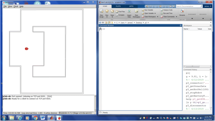
The figure above shows the computer desktop with the MobileSim simulator on the left and the Matlab command window placed on the right
-
3.
To begin a simulation with MobileSim, in the Matlab command prompt type
$${\gg} {\text{p}}3\_{\text{connector}}\left({ {\text{`MobileSim'}}} \right)$$

This will establish a connection with MobileSim through the local TCP/IP port. The sonar beams on the simulated robot will immediately appear and status information will be printed in the Matlab command window.
-
4.
Now you can send motion commands to the robot, using commands, such as p3_setRotVel and p3_setTransVel. For example, to make the robot drive in a circular path, set the translational velocity to 200 mm/s and the rotational velocity to 10 °/s using the following commands:
$$\begin{array}{*{20}l} { {\gg} {\text{p}}3\_{\text{setRotVel}}\left( {10} \right)} \hfill \\ { {\gg} {\text{p}}3\_{\text{setTransVel}}\left( {200} \right)} \hfill \\ \end{array}$$ -
5.
We can get the pose of the robot with the p3_getXYHeading function. This function has three outputs: the x and y coordinates in mm and the heading in degrees. To use the function in Matlab, we must define three output variables for use with the function. In the command prompt type
$${\gg} \left[ {{\text{x}},{\text{ y}},{\text{ heading}}} \right] = {\text{p}}3\_{\text{getXYHeading}}$$
The varibales x, y, and heading will be created in the Matlab workspace and contain the current pose data for the robot.
-
6.
MobileSim can also simulate the built in sonar sensors. The P3 mobile robot uses a forward and rear sonar array totaling 16 sonar sensors. We can retrieve simulated sonar data with the p3_getSonarData function. For example,
$${\gg} \left[ {\text{sonarScan}} \right] = {\text{p}}3\_{\text{getSonarData}}$$
will return a [1 × 16] array sonarScan with distance measurement for each of the 16 sonar sensors installed on the robot. The units are provided in mm. Below is a typical output returned from this function.

The elements in the sonarScan array correspond to the distance measured with each sensor in order counterclockwise from Sonar 0 to Sonar 15. See Fig. 9 and Table 4.

Sonar array front and back
-
7.
When the user is ready to terminate the simulation, we disconnect from MobileSim using the following command:
$$> > {\text{p}}3\_{\text{disconnector}}$$
This function closes the TCP/IP connection to MobileSim and stops the running timers. Be sure to do this at the end of a simulation.
-
8.
These functions described here can be incorporated into Matlab scripts to enable desired robot behavior, such as navigation to a desired goal coordinate, obstacle avoidance, wall following, and mapping, as well as other related tasks. See for example the script example_wander.m in “Appendix 1”.
2.3 Connect to the real robot
Connection to the actual P3 robot is similar to the steps to connect and interact with MobileSim. The only difference is that communication with the real robot occurs via the hardware serial port. The P3 mobile robot has a hardware serial port located on its control panel. The default baud rate is 9600 bps. Usually, to accomplish this connection, we use a pair of serial-to-wiFi adapters, such as the Moxa NPort W2150. One adapter is attached to the serial port on the desktop PC, while the second adapter is connected to the hardware serial port on the robot’s control panel. This allows the robot to move freely in the available floor space. The adapter on the robot is powered directly from the robot’s auxiliary 12 VDC power.
-
1.
Power up the robot and verify that the serial-to-wiFi adapter is working properly. Follow the manufacturer’s instructions to configure your selected adapter to function properly. Figure 10 shows the equipment setup using the Moxa W2150 serial-to-wiFi adapter.
Fig. 10 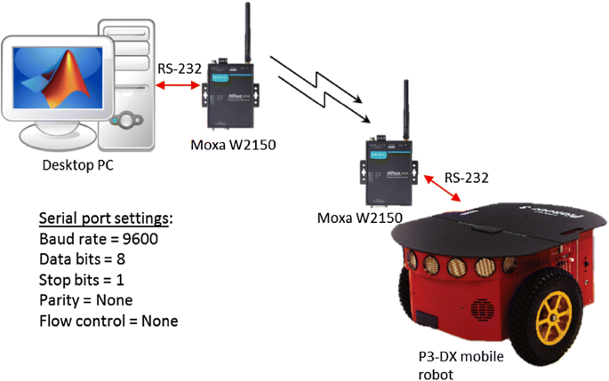
Equipment layout and set up for use with real robot
-
2.
To begin communications with the real robot, use the p3_connector function, as before, except that we use the desired serial port. Usually this is Com1 for a Windows PC or ttyS0 on a Linux computer. For example, on a Windows PC, in the Matlab command prompt we use
$${\gg} {\text{p}}3\_{\text{connector}}\left( {{\text{`Com1'}}} \right)$$

The status of the connection will be displayed in the command window. If this is successful, then you can proceed as before to send motion commands to the robot or read sonar data and pose data. See the example scripts provided to learn how to do this.
-
3.
As with MobileSim, to disconnect from the real robot, use the p3_disconnector function. This function will close the serial port, stop the running timer objects, and then exit the script.
Rights and permissions
About this article

Cite this article
Calusdian, J., Yun, X. A simple and highly portable MATLAB interface for learning robotics. SN Appl. Sci. 1, 890 (2019). https://doi.org/10.1007/s42452-019-0941-2
Received:
Accepted:
Published:
DOI: https://doi.org/10.1007/s42452-019-0941-2