
Abstract
In the heat treatment process, during the quenching of aluminum alloy, a high level of residual stresses is observed due to the severe thermal gradient at the surface and center of the work piece, which acts as the main source of distortion in machined parts. This article attempts to investigate the correlation between quench-induced residual stresses and the distortion of thin-walled parts during machining. The effects of polymer and uphill quenching methods in comparison with water quenching in the reduction of residual stresses are investigated on an experimental basis. By conducting the machining tests, the effects of residual stress on distortion and the effect of material removal in machining on stress redistribution are investigated. The results indicate that by adopting the polymer quenching method, the level of residual stress and distortion can be reduced significantly. According to the results, material removal in machining causes an imbalance in the compressive and tensile stresses, leading to a redistribution of the stress and distortion.
Introduction
In aerospace industries, the design and use of thin-walled monolithic parts made of aluminum alloys with a high strength-to-weight ratio have significantly increased since a reduction in the overall weight of the components, a reduction in fuel consumption, and a compact size are highly valued. In machining of thin-walled parts, up to 98% of the volume of the raw material is removed (Ref 1). The main problems in machining of thin-walled parts made of high-strength aluminum alloys are distortion and dimensional instability, which lead to an increase in distorted part scraps and production costs. According to a study conducted by Boeing Company on the manufacturing schedule of four different airplanes, the cost of waste materials and the rework related to the distortion of machined parts was estimated at over 290B USD (Ref 2). Distortion in parts can range from a few micrometers in small pieces to several centimeters in large pieces. In general, distortion and dimensional instability in machined parts made of aluminum alloy is a function of the residual stresses in the material (Ref 3). The residual stress results from the heat treatment, material processing, and machining operations where the stresses caused by the heat treatments have a higher intensity (Ref 4). In the heat treatment of high-strength aluminum alloys, in order to achieve maximum mechanical properties, the material is heated up to 400-500 °C, which leads to the dissolution of the alloy elements, such as magnesium and copper in the alloy structure. An increase in the dissolution of the alloy elements leads to an increase in strength and hardness. To prevent precipitation of alloying elements and achieve the desired mechanical properties, the quenching process is applied, a key factor in generating residual stresses in the raw material (Ref 5).
In the quenching process, as the work piece at high temperature is immersed in water, the contraction rate is much higher at the surface than in the center of the piece. After rapid cooling of the surface, the yield strength sharply increases and due to the fast contraction, the surface areas absorb the surrounding zones, leading to a compressive stress at the surface areas. Due to the lower yield strength in the central regions of the part, these areas are subject to extension through areas, which have compressive stresses, leading to the generation of tensile residual stresses in the central area (Ref 6). The final state of the residual stress is related to the geometry of the work piece, thickness, and applied heat gradient during the quenching process.
Quench-induced residual stresses are self-balancing, in the sense that the tensile and compressive residual stress levels will be balanced by the deformation of the part. In machining of quenched parts, removing a portion of the material leads to an imbalance between tensile and compressive residual stresses causing the deformation of the parts until the stresses are balanced again (Ref 7). Increasing the stress level in the quenching process causes an increase in the distortion of machined parts, especially thin-walled parts; therefore, reducing quench-induced residual stresses is the main factor in reducing distortion. Decreasing the thermal gradient from the center of the work piece to surface is the key to reducing the quenching residual stresses. One of the methods adopted in this process uses hot water as a quenching fluid, causing a decrease in the thermal gradient of the work piece, where the high water temperature reduces the aluminum alloy strength (Ref 8). Another method for reducing the thermal gradient is using a water-based soluble polymer, like polyalkylene glycol (PAG) to improve the cooling properties of the quenching fluid. When a hot object is immersed into a water-based polymer solution, the polymers in the liquid convert into fibers and cover the whole work piece. This layer acts as an insulator, causing uniform cooling and reducing the level of residual stresses (Ref 9).
The thermal gradient in the conventional quenching process is due to the immersion of a hot object into a cold environment; therefore, this trend can be reversed, which may create stress with an inverse distribution that leads to the neutralization of generated stress in water quenching. This idea is the basic solution for reducing the level of residual stresses in the inverse or uphill quenching method; where, after the conventional water quenching, the parts are stored at a very low temperature (−180 °C) and then exposed to a high temperature (200 °C). In uphill quenching, the tensile residual stresses are generated at the surface areas and the compressive stresses in the center of the piece, which eventually lead to the neutralization of stress caused by water quenching and the reduction of the level of residual stress (Ref 10).
In recent decades, many studies have been conducted through experimental research (Ref 11-13), the finite element model (Ref 14, 15) and a combination of other methods (Ref 16) in order to predict the residual stresses caused by the heat treatment processes. The correlation between quench-induced residual stresses with distortion is the subject of many studies. Chatelain et al. (Ref 17) studied the effect of residual stresses in raw material on machining distortion of parts in an empirical manner. They found that by reducing the level of residual stresses in the initial raw material, the distortions will be reduced after machining. They reported that the manner by which the residual stresses are distributed in the parts is effective on distortion. Robinson et al. (Ref 18) conducted an empirical investigation on the impact of removing material by machining on deformation and stress distribution in quenched parts. Their results indicate that the material removal causes the redistribution of residual stresses in the work piece and no stress relaxation is observed, because the strain energy intensity is equal for both the un-machined and machined blocks. Wang et al. (Ref 19) compared the effectiveness of different approaches by studying different types of stress relieving techniques. Their results indicate that using a polymer solution in quenching reduces the level of residual stresses up to 67% compared to water quenching. They reported that the use of mechanical stress relieving methods can reduce the quench-induced residual stress up to 90%. Croucher (Ref 7) examined the effectiveness of the uphill quenching for relieving stress in quenched parts. His results indicate that the most appropriate method is using liquid nitrogen and high-pressure vapor, which would lead to an 80% reduction in residual stress. In addition to the aforesaid works, many studies have been carried out to investigate the effect of machining-induced residual stress (Ref 20-23). Denken et al. (Ref 1) proved the direct effect of these parameters on the distribution of machining-induced residual stresses. Denken et al. (Ref 24) claimed that the exerted thermal and mechanical loads on a thin-walled work piece during machining may induce significant deviation in the dimensions of the work pieces. Nowag et al. (Ref 25) declared that the induced forces by clamping the work pieces might cause remarkable elastic deformation in a thin-walled part during machining. Despite all the aforesaid efforts, the distortion and deformation mechanism of thin-walled parts have not been fully specified to date. Understanding and accurately predicting the residual stress distribution is possible only in a qualitative sense while there are great uncertainties about the causes and mechanisms of residual stress and distortion.
The objective of this article is to investigate the effect of quench-induced residual stresses on the machining distortion of thin-walled parts. In the present study, several cylindrical thin-walled parts are heat treated by the above-mentioned three methods. The effectiveness of each method in relieving stress is investigated by measuring the residual stresses. The correlation between the levels of residual stresses with distortions and the effect of removing material by machining on the redistribution of residual stresses are studied as well.
Experimental Procedure
Experimental Design
To evaluate the effectiveness of polymer and uphill quenching methods in reducing residual stresses, in comparison with water quenching, several experiments are carried out on cylindrical work pieces made of Al7075-T6 with a diameter of 60 mm. The work pieces are divided into three groups and exposed to different experimental conditions. The first group is heated in a heat chamber for 20 min at 470 ± 5 °C for solution heat treatment. Next, the parts are quenched in a water container at 25 °C and are then placed in the furnace at 120 °C for 24 h subject to the aging treatment (T6). It is estimated that the aging reduces quench-induced residual stresses by 15% (Ref 7). The second group, after being subject to the solution heat treatment, is quenched in a 32% polymer solution of polyalkylene glycol (PAG UCON A) and then the parts are put through the aging operation (solution and aging treatment here are identical to that of the first group). The third group, after the solution heat treatment and water quenching (same conditions as the first group), is submerged in a container of liquid nitrogen at −196 °C for 30 min. After this period, the parts are placed in a steam chamber exposed to a water vapor pressure of 14 bars until the temperature of parts reaches approximately at 200 °C and then the parts are exposed to the aging treatment. The diagram of time-temperature for the three different groups is presented in Fig. 1(a).

(a) The time-heat diagram of the quenching methods, (b) Geometry of work piece, and (c) the measurement positions of the geometric tolerances in the work piece (Color figure online)
In order to investigate the effect of different quenching conditions on the mechanical properties and microstructure, the hardness measurement and metallographic examination are carried out on all quenched parts. A Vickers hardness tester (UV1 model made by Koopa Co.) is employed for measuring the hardness distribution using an indentation load of 30 kg and dwell time of 10 s. In each part, the hardness is measured in the radial direction in 23 points. Metallographic images of the three quenched parts are captured at a distance of 20 mm by a microscope (352a model made by IOI Co.).
Machining Conditions
After the heat treatment process, in order to investigate the effect of quench-induced residual stresses on the distortion of machined parts, the machining experiments are performed on the above-mentioned three groups. Machining experiments are performed using a CNC machine (Model TC50, Tabriz Machine Manufacturing Co., Iran). Parts are machined to their final dimensions in two stages: first, the parts are machined through a few steps to gain an internal diameter of 55 and external diameter of 59 mm with a length of 55 mm (rough machining). Rough machining is performed using a carbide tool (VCMW160404FP-Sandvik) at a cutting speed of 470 m/min, feed rate of 120 mm/min, and depth of 2 mm. Next, the parts are machined to an internal diameter of 55 and external diameter of 58 mm (finishing). The finishing stage is performed using a PCD tool (VCGX 16 04 04-AL-Sandvik) at a cutting speed of 230 m/min, feed rate of 6 mm/min, and depth of 0.5 mm, using coolant fluid. The geometry of the work piece is shown in Fig. 1(b). In these experiments, in order to prevent the exertion of pressure by the three-jaw chuck on the work piece and its deformation, the work piece is bolted on a fixture that is clamped by the chuck. Using this technique ensures that the measured distortion is not caused by the pressure exerted through the three-jaw chuck.
Distortion Measurement
In order to assess the distortion level in the machined parts, the geometrical tolerances of the parts in different sections are measured by a form measuring machine (model 4004 made by Hommel Co.), twice, immediately after machining and a week later. During one week, as the time interval between the two measurements, the work pieces are kept in a laboratory environment subject to the standard ambient temperature (20 °C and 50% humidity). To measure the distortion with high accuracy, the circularity tolerance is measured in five sections on the external surface of the parts. Similarly, the straightness tolerance on the external surface of parts is measured along with three axes at 120 degrees of difference. The sums of the differences in the geometrical tolerances for two periods of measurements are considered as distortion. An indexing position is marked on all work pieces and the form measuring machine in order to clamp the work pieces exactly on the primary measurement position in the second round of measurement. This issue is very important in measuring the straightness tolerance for the second round because the machine probe should be placed exactly where the primary measurement was made. The measurement positions of the geometric tolerances in the work piece are shown in Fig. 1(c).
Residual Stress Measurement
To measure the quenching stresses, the contour method is used. The contour method is a newly developed method, first published in 2001 (Ref 26) and has the potential to measure a full cross-sectional profile of the residual stresses. The basis of the contour method is derived from Bueckner’s superposition principle (Ref 27). This method involves making a straight cut in the sample along a plane where level and the distribution of residual stresses are required. The cut surfaces deform locally due to the relaxation of residual stresses present prior the cut. These deformations are measured and then applied as a boundary condition in a finite element model to determine the out-of-plane residual stress distribution at the cut surface. The contour method is implemented through the following four steps: specimen cutting, contour measurement, data processing (Smoothing), and stress calculation using the finite element method (FEM). More detail on the procedures and principles of the contour method can be found in references (Ref 27-29). The contour method in this research work is used to determine the normal component of stress (normal to the surface of the cut), i.e., σ xx . The four steps of stress measurement in quenched parts are explained as follows:
-
1.
Cutting: Cutting is the most important step in the measurement of residual stress in the contour method. The quality of measurement depends significantly on the quality of the cut. The most appropriate process for cutting the parts in half in the contour method is the wire electrical discharge machining (WEDM). This process can make an accurate straight cut without any plastic deformation on the surface. Movement of the work piece is restrained by clamping it on a fixture. Before cutting, the fixture and the work piece are placed inside the dielectric fluid chamber (deionized water) of the WEDM machine to allow the fixture and the work piece to reach the designated thermal equilibrium. The fixture and cutting line on the quenched part are shown in Fig. 2(a).
Fig. 2 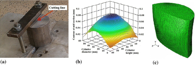
(a) The fixture and cutting line on the quenched part, (b) the Smoothed contour, and (c) the FEM model of the half cylinder with the applied displacements on nodes (Ref 29) (Color figure online)
-
2.
Contour measurement: After cutting, the surface contours of both halves are measured through the coordinate measuring machine (CMM), Fig. 2(b). The contours of surfaces are measured by the continuous motion of the probe on the surfaces along the lines from one edge of the specimen to the opposite edge. The measurement is performed on both cut surfaces of each part. During the measurements, the probe has continuous contact with the cut surface of the part. The diameter of the CMM probe tip was 1 mm with an accuracy of 0.1 μm.
-
3.
Smoothing: In order to prevent problems that may happen during the contour measurements, such as noise and recorded false points caused by forces that are too low or high on the probe and surface roughness, the measured displacements must be smoothed before being applied as the boundary conditions. In order to smooth out the noise, the measured contours are fitted to a Fourier series bivariate order 2 × 5. The average of both surfaces are then calculated and reversed subsequently by the TableCurve 3D software. The values at nodal locations are then applied to the cut surface as the boundary conditions. The smoothed contour is shown in Fig. 2(c).
-
4.
The FEM Model: To determine the distribution of residual stresses, a FEM model with the commercial code ABAQUS is adopted. The averages of the measured displacements (averaged smoothed contour) are fed to a FEM model as the boundary conditions. This process is performed using the ABAQUS user subroutines, called DISP. This subroutine is written by The Fortran software first and then linked to the ABAQUS. The three-dimensional FEM model of the half cylinder with the applied displacements on the nodes is shown in Fig. 2(c). Deformation is exaggerated in the figure by a factor of 70% in order to provide a better demonstration. After applying the displacement to the model as the boundary conditions, the residual stress level and distributions are calculated.

Results
The Effect of Quenching Conditions on Residual Stress
The contours of the residual stress distribution (σ xx ) for the three parts quenched under three different conditions are shown in Fig. 3 and the residual stress distribution (σ xx ) in both the axial and radial directions of the parts are shown in Fig. 4. In the part subject to water quenching, a severe thermal gradient is generated at the surface and the center of the part during quenching, leading to the formation of high levels of compressive stresses at the surface and tensile stresses in the center of the part. The stress at the surface region reaches −230 MPa and in the central areas 100 MPa. In Fig. 4, in both the axial and radial directions, the compressive and tensile stresses are developed on the surface and in the center of the parts, respectively. In either direction, the level of tensile stresses in the center of the three work pieces are close to one another, but the levels of the compressive stresses in the surface areas are significantly different. In the radial direction, the compressive stress level is much higher than that of the axial direction; moreover, the stresses on both sides of the parts in the radial direction have a non-uniform distribution. For example, in the part subject to water quenching, in the axial direction, the distribution of compressive stresses on the surface is the same on both sides of the work piece with a level of stress of about 60 MPa. In contrast, in the radial direction, the compressive stress on both sides of the work piece has a non-uniform distribution so that the stress on one side reaches −150 MPa while on the other side it is −230 MPa. This difference indicates the influence of geometry on the distribution of residual stresses and the variation of thermal gradient in different sections of the parts.

The Contour of residual stress distribution in the quenched parts (Color figure online)

Residual stress distribution in axial and radial directions in the quenched parts
In the part subject to polymer quenching, the compressive and tensile stresses are developed on the surface and at the center, which are significantly lower compared to the part subject to water quenching. Reduction in the level of residual stresses in the polymer quenched part compared to the water quenched part is related to their different quenching mechanisms.
In water quenching, when a hot piece is immersed into water, a vapor film covers the whole piece and acts as an insulator with a low heat transfer rate. As the temperature of the part decreases, the vapor film is removed and the work piece surface comes in direct contact with the water, causing the media to boil.
At this stage, due to a heat transfer rate that is about 100 times greater than the initial stage (vapor film stage), the work piece temperature is sharply reduced.
When the temperature of the work piece decreases below the water boiling point, the boiling stage ends and the heat transfer follows the conduction mechanism, which is at a remarkably lower rate of heat transfer than at the boiling stage.
Varying cooling rates in these three steps lead to a non-uniform thermal gradient in the work piece, which leads to a non-symmetric distribution of stress. It is possible that these three steps occur simultaneously in separate sections of the work piece, causing differing thermal gradients in different sections of the part, which could lead to both an increase in the residual stress level and a non-uniform distribution of stresses.
In polymer quenching, when a hot piece is immersed into the polymer solution, the polymers in the solution dissolve and convert to a polymer film, covering the whole piece. This film acts as an insulator with a perfect uniform cooling rate that leads to the reduction of the thermal gradient in the part, hence a significant reduction in the residual stresses. In the uphill quenched part, the level of residual stresses is considerably reduced compared to the quenched part using water (Fig. 3 and 4).
In both the axial and radial directions, the compressive and tensile stresses are created at the surface and center of the work piece, respectively, which is in contrast to the theories and results presented by other researchers who have reported that the stress distribution is almost uniform throughout the work piece and the stress level is close to zero (Ref 6, 19). Failure to achieve the expected level of stress relief in uphill quenching is due to its complicated implementation. This method is full of complexities where precision and accuracy in temperature control are very important, in nitrogen immersion and steaming stages in particular. The steaming stage in uphill quenching is costly and associated with numerous limitations, such as the necessity of the proper fixtures to regulate uniform temperature across the part.
The amount of stress relief in the uphill quenched part in this study is close to that of the polymer quenched parts. On the contrary, the polymer quenching process is very simple, cheap, and less time consuming. A close observation of the contours in Fig. 3 indicates that the residual stresses in the polymer quenched part have more uniform distribution than that of the uphill quenched part due to its uniform thermal gradient.
The Effect of Quenching Conditions on Hardness and Microstructural Change
In order to investigate the effect of different quenching conditions on mechanical properties, the hardness profile is measured in the three quenched parts. Vickers hardness profiles as a function of thickness for the three quenched parts are shown in Fig. 5. According to the results, the average hardness of the parts subjected to water and uphill quenching is about 10% higher compared to the one subject to polymer quenching. Lower hardness in the polymer quenched part is negligible against the level of stress reduction in this part. The difference in hardness of the three quenched parts is related to different cooling rates in the quenching methods. The cooling rate is directly related to the hardness of the quenched part so that an increase in the cooling rate leads to an increase in hardness of the alloy after quenching. An uneven hardness distribution can be observed in the water quenched part. In this part, with an increase in the distance from the surface, the hardness of the alloy is reduced. This trend is related to severe cooling and limited precipitation at the surface areas, leading to an increase in hardness. An increase in depth makes the cooling rate decrease, leading to a reduction in hardness. This trend is similar for the polymer quenched part, but the difference in the hardness of the central and surface areas is lower than that of the water quenched part. In the polymer quenched part, the uniform cooling rate leads to a reduction in the thermal gradient. As a result, the hardness fluctuations in the whole cross section of the part are reduced. In contrast, the distribution of hardness in the uphill quenched part is very erratic, which is mainly due to severe strain occurrence during this quenching method.

Hardness profiles as a function of thickness (Color figure online)
It was found that high cooling rates lead to better mechanical properties (Ref 30). However, high cooling rates cause high temperature gradients as well, which can result in high levels of residual stress. The obtained results here indicate that the polymer and uphill quenching methods can be selected to obtain the desired mechanical properties while minimizing the residual stress. The high level of hardness in part may be a sign of high residual stress, which could be considered as a result of this study and can be investigated in future studies.
The microstructure is also examined to investigate whether the change in microstructure could be distinguished as a function of the quenching condition. Metallographic images of the three quenched parts captured at a distance of 20 mm from the quenched surface are shown in Fig. 6 where different microstructures are observed in different parts. In the part subject to water quenching Fig. 6(a), which experienced a high cooling rate, very little etching of the grain boundaries is observed and no significant recrystallization has occurred. As can be seen in this image, grain boundaries are outlined parallel to the rolling direction. Very small etching of the grain boundaries perpendicular to the rolling direction can be observed and precipitation in both the grain and grain boundaries is clearly evident. Since the material used in this research is Al7075, these precipitates are mainly insoluble particles of FeAl3 (Ref 31).

The optical micrographs of the three quenched parts: (a) water quenched part (b) uphill quenched part (c) polymer quenched part
In contrast, as seen in Fig. 6(b), the part exposed to uphill quenching, which experienced the same cooling rate as that of the water quenched part in the first step, has a different microstructure. In this image, there are some large grains that are outlined parallel to the rolling direction, however, in some grains recrystallization has occurred, leading to the formation of smaller grains. Therefore, in this microstructure there is a combination of large grains as well as new recrystallized smaller grains. As with the previous image, precipitates of FeAl3 are dispersed in both the grain and grain boundaries. This result indicates that the thermal gradient in the second step of uphill quenching has a great influence on the microstructure. In addition, the second step of uphill quenching is accompanied by mechanical deformation that could have an influence on the microstructure’s changes.
In the polymer quenched part shown in Fig. 6(c), the recrystallization areas are obvious and as with the uphill quenched part, the microstructure is constituted by large grains and new recrystallized smaller grains. However, the new recrystallized grains are smaller in comparison with the uphill quenched part. This difference can be attributed to a lower cooling rate in the polymer quenching method.
According to the obtained results, the recrystallization of microstructure can be significantly affected by the quenching condition. It can be claimed that the lower cooling rate likely leads to more recrystallization, which is in agreement with the results obtained by Zhang and Newkirk (Ref 32, 33).
The Effect of Residual Stress on Distortion
In order to investigate the effect of quenching stress and its distribution on the distortion of thin-walled parts, caused by machining, the same machining experiments are performed on three groups of quenched parts. To ensure the accuracy of the results, each experiment is repeated 3 times. The average amounts of measured distortions in three different parts are shown in Fig. 7. According to Fig. 7, the highest distortion is measured on the water quenched part, which has the highest residual stress level, meaning the total amount of distortion at different sections of it reaches 117.25 µm. In the polymer and uphill quenched parts, the measured distortions are significantly reduced to about one-third compared to the water quenched part with a distortion of 44.72 and 36.17 µm, respectively. The results indicate a direct influence of quench-induced residual stresses on the distortion.

The distortion average of the quenched part after machining
The residual stresses are defined as mechanical stresses in a solid body, which is not directly exposed to forces or torques with no temperature gradient. The internal equilibrium of a part depends on the state of the residual stresses on it. The total residual tensile and compressive stresses in a part must be equal and balance each other (Ref 7). After machining, when area of a part that has tensile or compressive residual stress is removed, an imbalance occurs in the internal stresses. Thus, the part distorts to maintain a balance between the tensile and compressive stresses. According to the results obtained here, it can be concluded that with an increase in the level of quench-induced residual stresses, the imbalance rate between the tensile and compressive stresses after machining will be increased, leading to an increase in the distortion and dimensional instability of the part.
Redistribution of Residual Stresses After Machining
To investigate the redistribution mechanism of residual stresses in a water quenched part after removing material by machining, an area of the part is removed by the wire EDM process, Fig. 8(b). After cutting, the distribution of residual stresses is measured through the contour method. The geometry of the work piece before and after machining and the cutting plate of the work piece for measuring the residual stress are shown in Fig. 8. The contours of the residual stress distribution for the machined and un-machined parts are shown in Fig. 9.

(a) The quenched part (b) the machined part (c) the cutting plate for stress measurements

The residual stress distributions in the machined and un-machined parts (Color figure online)
As seen in Fig. 9, material removal in machining leads to an imbalance and redistribution of the residual stresses, thus developing a new state of stress in the part. In the machined part, the tensile stresses in the center of the work piece are almost stable, with a slight reduction in their levels. Redistribution of stresses has even led to the formation of the tensile stress in certain areas of the parts’ surface. At the surface of the quenched part, compressive stresses are developed, but the redistribution of the stresses after material removal leads to the formation of tensile stresses at the surface areas. The removed materials by machining mostly had compressive stresses. Therefore, to reach a balance between the tensile and compressive stresses, the level of tensile residual stress in the central area is noticeably reduced. These results indicate that the geometrical position of the removed material has a significant effect on the redistribution of residual stresses.
Conclusion and Outlook
The effect of the quench-induced residual stresses on the machining distortion of thin-walled parts was studied. Several Al-7075 cylindrical work pieces were heat treated through three different quenching methods and the effectiveness of each method in stress relieving was determined by measuring the residual stress distribution. The correlation between the levels of residual stress with distortion was examined as well. The results indicate that the level and distribution of residual stresses are directly related to distortion. With an increase in quench-induced residual stresses, the amount of imbalance in internal stress after machining will be increased, leading to an increase in the distortion and dimensional instability of the parts. Therefore, the key strategy in reducing distortion in thin-walled parts is to reduce the residual stress in the heat treatment. According to the results, when quenching aluminum alloy parts in water, severe thermal gradients and various cooling rates lead to the development of very high levels of residual stresses. In the quenched parts, the compressive stresses are developed at the surface and the tensile stresses are developed in the center of the part. The investigation of uphill and polymer quenching methods indicates that applying the polymer solution as a quenching fluid can reduce the thermal gradient in a more effective manner. In the polymer quenched parts, the stress levels were significantly lower than that of the water-quenched parts. Moreover, polymer quenching is more feasible in comparison with the uphill quenching, which requires expensive equipment and unique fixtures for any particular geometry. Therefore, the use of the polymer quenching method in sensitive thin-walled parts with high potential of distortion is highly recommended.
The results show that different quenching conditions can lead to a change in the microstructure and hardness level of the part. Assessing the hardness indicates that the part subject to polymer quenching has a 10% lower hardness than the other two quenched parts, which is negligible compared to the level of stress reduction in this part. The effect of material removal by machining on the redistribution of residual stresses was investigated as well. The results clearly indicate that removing material by machining causes an imbalance in the compressive and tensile stresses, leading to the redistribution of the stresses. In the machined part, the redistribution of stresses leads to the formation of a high level of tensile stresses at the surface of the quenched part, which corresponds to the geometrical position of removed material and the nature of the residual stress. In conclusion, selecting the proper geometry for quenching in accordance with the final shape of the part after machining and adopting a proper strategy for machining, like symmetrical machining, would reduce the distortion potential in thin-walled parts.
References
Q. Zhang, M. Mahfouf, J.R. Yates, C. Pinna, G. Panoutsos, and S.L. Boumaiza, Modeling and Optimal Design of Machining-Induced Residual Stresses in Aluminium Alloys Using a Fast Hierarchical Multiobjective Optimization Algorithm, Mater. Manuf. Process., 2011, 26(3), p 508–520
D.M. Bowden and J.E. Halley, Aluminium Reliability Improvement Program-Final Report 60606, The Boeing Company, Chicago, IL, 2011
S. Saini, I.S. Ahuja, and V.S. Sharma, Residual Stresses, Surface Roughness, and Tool Wear in Hard Turning: A Comprehensive Review, Mater. Manuf. Process., 2012, 27(6), p 583–598
P.J. Withers and H.K.D.H. Bhadeshia, Residual Stress. Part 2—Nature and Origins, Mater. Sci. Technol., 2001, 17(4), p 366–375
B. Liscic, Heat Transfer Control During Quenching, Mater. Manuf. Process., 2009, 24(7–8), p 879–886
B. Liscic, H.M. Tensi, L.C. Canale, and G.E. Totten, Quenching Theory and Technology, CRC Press, Boca Raton, 2011
T. Croucher, Minimizing Machining Distortion in Aluminum Alloys through Successful Application of Uphill Quenching—A Process Overview, J. ASTM Int., 2010, 1523, p 332–351
D.A. Tanner and J.S. Robinson, Residual Stress Magnitudes and Related Properties in Quenched Aluminum Alloys, Mater. Sci. Technol., 2006, 22(1), p 77–85
T. Croucher, Using Polyalkylene Glycol Quenchants to Effectively Control Distortion and Residual Stresses in Heat Treated Aluminum Alloys, J. ASTM Int., 2010, 1523, p 309–331
D.A. Lados, D. Apelian, and L. Wang, Minimization of Residual Stress in Heat-Treated Al-Si-Mg Cast Alloys Using Uphill Quenching: Mechanisms and Effects on Static and Dynamic Properties, J. Mater. Sci. Eng. A., 2010, 527(13), p 3159–3165
J.S. Robinson, S. Hossain, C.E. Truman, A.M. Paradowska, D.J. Hughes, R.C. Wimpory, and M.E. Fox, Residual Stress in 7449 Aluminium Alloy Forgings, J. Mater. Sci. Eng. A., 2010, 527(10), p 2603–2612
J.S. Robinson, D.A. Tanner, S. Van Petegem, and A. Evans, Influence of Quenching and Aging on Residual Stress in Al-Zn-Mg-Cu alloy 7449, Mater. Sci. Technol., 2012, 28(4), p 420–430
Z. Li, A.M. Freborg, B.D. Hansen, and T.S. Srivatsan, Modeling the Effect of Carburization and Quenching on the Development of Residual Stresses and Bending Fatigue Resistance of Steel Gears, J. Mater. Eng. Perform., 2013, 22(3), p 664–672
X. Yang, J. Zhu, Z. Nong, Z. Lai, and D. He, FEM Simulation of Quenching Process in A357 Aluminum Alloy Cylindrical Bars and Reduction of Quench Residual Stress Through Cold Stretching Process, Comput. Mater. Sci., 2013, 69, p 396–413
X.W. Yang, J.C. Zhu, Z.H. Lai, Y. Liu, D. He, and Z.S. Nong, Finite Element Analysis of Quenching Temperature Field, Residual Stress and Distortion in A357 Aluminum Alloy Large Complicated Thin-Wall Workpieces, Trans. Nonferrous Met. Soc. China, 2013, 23(6), p 1751–1760
L. Da-feng, D. Hua-feng, L. Li-bin, W. Meng, and C. Kui, Numerical Simulation and Experimental Study of Quenching-Induced Residual Stress in 7075 Aluminum Alloy Plates, Mech. Res. Appl., 2012, 3, p 033
J.F. Chatelain, J.F. Lalonde, and A.S. Tahan, Effect of Residual Stresses Embedded within Workpieces on the Distortion of Parts after Machining, Int J Mech., 2012, 6(1), p 43–51
J.S. Robinson, D.A. Tanner, C.E. Truman, and R.C. Wimpory, Measurement and Prediction of Machining Induced Redistribution of Residual Stress in the Aluminium Alloy 7449, Exp. Mech., 2011, 51(6), p 981–993
Q.C. Wang, Y.L. Ke, and H. Xing, Evaluation of Residual Stress of Aluminum Alloy 7075 by Using Crack Compliance Method, Trans. Nonferrous Met. Soc. China, 2003, 13(5), p 1190–1193
S. Masoudi, S. Amini, E. Saeidi, and H. Eslami-Chalander, Effect of Machining-Induced Residual Stress on the Distortion of Thin-Walled Parts, Int. J. Adv. Manuf. Technol., 2014, 76(1–4), p 597–608
F.J. Campa, L.N. Lopez de Lacalle, and A. Celaya, Chatter Avoidance in the Milling of Thin Floors with Bull-Nose end Mills: Model and Stability Diagrams, Int. J. Mach. Tool Manu., 2011, 51(1), p 43–53
S. Smith and D. Dvorak, Tool Path Strategies for High Speed Milling Aluminum Workpieces with Thin Webs, Mechatronics, 1998, 8(4), p 291–300
S. Seguy, F.J. Campa, L.N. Lopez de Lacalle, L. Arnaud, G. Dessein, and G. Aramendi, Toolpath Dependent Stability Lobes for the Milling of Thin-Walled Parts, Int. J. Mach. Mach. Mater., 2008, 4(4), p 377–392
B. Denkena, C. Schmidt, and M. Krüger, Experimental Investigation and Modeling of Thermal and Mechanical Influences on Shape Deviations in Machining Structural Parts, Int. J. Mach. Tool Manu., 2010, 50(11), p 1015–1021
L. Nowag, J. Sölter, A. Walter, and E. Brinksmeier, Effect of Machining Parameters and Clamping Technique on Residual Stresses and Distortion of Bearing Rings, Materialwiss. Werkstofftech., 2006, 37(1), p 45–51
M.B. Prime, Cross-Sectional Mapping of Residual Stresses by Measuring the Surface Contour After a Cut, J. Eng. Mater. Technol., 2001, 123(2), p 162–168
H. Bueckner, The Propagation of Cracks and the Energy of Elastic Deformation, Trans. ASME., 1958, 80, p 1225–1230
N.S. Rossini, M. Dassisti, K.Y. Benyounis, and A.G. Olabi, Methods of Measuring Residual Stresses in Components, Mater. Des., 2012, 35, p 572–588
A.H. Mahmoudi, A.R. Hosseinzadeh, and M. Jooya, Plasticity Effect on Residual Stresses Measurement Using Contour Method, IJE Trans. A, 2013, 26(10), p 1203–1212
S. Ma, M.D. Maniruzzaman, D.S. MacKenzie, and R.D. Sisson, Jr., A Methodology to Predict the Effects of Quench Rates on Mechanical Properties of Cast Aluminum Alloys, Metall. Mater. Trans. B, 2007, 38(4), p 583–589
L.F. Mondolfo, Aluminum Alloys: Structure and Properties, Elsevier, New York, 2013
J. Zhang, Y. Deng, W. Yang, S. Hu, and X. Zhang, Design of the Multi-stage Quenching Process for 7050 Aluminum Alloy, Mater. Des., 2014, 56, p 334–344
J.W. Newkirk and D.S. MacKenzie, The Jominy end Quench for Light-Weight Alloy Development, J. Mater. Eng. Perform., 2000, 9(4), p 408–415
Acknowledgments
The authors thank Dr. Amir Hossein Mahmoudi for his valuable assistance in measuring the residual stresses at Bu Ali Sina University, Hamedan, Iran. The authors would like to thank the research board of Islamic Azad University of Najafabad for supporting this research.
Author information
Authors and Affiliations
Corresponding author
Rights and permissions
About this article

Cite this article
Masoudi, S., Amirian, G., Saeedi, E. et al. The Effect of Quench-Induced Residual Stresses on the Distortion of Machined Thin-Walled Parts. J. of Materi Eng and Perform 24, 3933–3941 (2015). https://doi.org/10.1007/s11665-015-1695-7
Received:
Revised:
Published:
Issue Date:
DOI: https://doi.org/10.1007/s11665-015-1695-7