
Abstract
Personal identification systems that use face recognition work well for test images with frontal view face, but often fail when the input face is a pose view. Most face databases come from picture ID sources such as passports or driver’s licenses. In such databases, only the frontal view is available. This paper proposes a method of 2D pose-invariant face recognition that assumes the search database contains only frontal view faces. Given a non-frontal view of a test face, the pose-view angle is first calculated by matching the test image with a database of canonical faces with head rotations to find the best matched image. This database of canonical faces is used only to find the head rotation. The database does not contain images of the test face itself, but has a selection of template faces, each face having rotation images of − 45°, − 30°, − 15°, 0°, 15°, 30°, and 45°. The landmark features in the best matched rotated canonical face such as say rotation 15° and it’s corresponding frontal face of rotation 0° are used to create a warp transformation to convert the 15° rotated test face to a frontal face. This warp will introduce some distortion artifacts since some features of the non-frontal input face are not visible due to self-occlusion. The warped image is, therefore, enhanced by mixing intensities using the left/right facial symmetry assumption. The enhanced synthesized frontal face image is then used to find the best match target in the frontal face database. We test our approach using CMU Multi-PIE database images. Our method performs with acceptable and similar accuracy to conventional methods, while using only frontal faces in the test database.
1 Introduction
Face recognition is one of the basic functions of a security system. It plays a crucial role in many applications such as biometric authentication, surveillance, and so on. A typical face recognition system identifies a person by matching a test face image to images in a frontal face database. Such databases often come from identification card systems such as passports, driver’s license, citizen cards, and so on. Face recognition algorithms that use frontal face image databases still have their own challenges, often resulting in recognition failure. These challenges come from the difference in the test image when compared to the target database due illumination variations, make-up changes, partial occlusion such as from eyeglasses, expressions, and pose (non-frontal) views [1, 2]. In practical applications, the input face image from a surveillance footage will likely exhibit pose variations. Pose variations are especially common in pictures obtained from security cameras. Biometric authentication systems for door access control, laptop use, and smartphone use may also need to be tolerant to some head orientation variations. This problem in sensitivity to pose variations often causes errors in face recognition [3]. Due to the limitless variations in pose view of faces, it becomes difficult to practically cover all possible poses and almost impossible to create databases containing all key pose-views. Our research problem statement is, therefore, to create an algorithm to recognize a face in any pose while only using a target face database containing only frontal view faces.
The goal of our paper is to recognize a test face image with pose views by using a database of target frontal faces. As part of preprocessing, each input face test image first undergoes a facial landmark extraction along with some size normalization. After that, we estimate pose view using a coarse-to-fine approach to find the closest matched pose face shape from a canonical face database that contains 6 rotated faces plus a frontal face for each canonical person. For example, if the test face matches face of person X at − 30° orientation, we will use the landmarks in X’s − 30° image and X’s frontal face (0° orientation) to create a 2D image warp transformation to get frontal view from − 30° view. We then use this transformation to create a synthesized frontal-view face image which is defined as a simple image transformed from pose-view face to a frontal-view image. After that we enhance the image a bit using ratio mixing symmetry face texture based on the pose view angle. This synthesized frontal face image is then used to search the target database. Our paper’s key contribution is in proposing an algorithm for 2D pose-invariant face recognition using a single frontal-view face database. We first find the pose-view angle to get a corresponding pose to frontal shape transformation. We then warp our test face image to get a frontal face to feed to the face recognition algorithm.
Section 2 of this paper discusses related literature. Section 3 presents a problem analysis along with certain basic algorithms used. Section 4 proposes the algorithm we used. Experiments and results are presented and discussed in Sects. 5 and 6, respectively. A conclusion is provided in Sect. 7.
2 Related Works
To recognize a face image with pose views, many researches propose approaches to pose-invariant face recognition (PIFR) which can be divided into two categories: 3D approaches [4,5,6,7,8,9,10] and 2D approaches [11,12,13,14,15,16,17,18,19].
In 3D based approaches, methods [4,5,6] essentially require 3D face data information to normalize pose-view by using the 3D face model for more accurate reconstruction. Blanz and Vetter [4] present a 3D morphable face model by using PCA algorithm on a set of aligned 3D face scans to create a synthesized frontal face image. Later, Asthana et al. [7] proposed a method for unsupervised PIFR to project the 2D face image to a 3D generic face model. They then synthesize face images under new poses using the textured 3D model. Yi et al. [8] present a method to extract Gabor magnitude features from much denser landmarks located by a 3D morphable face model. These works [7, 8] depend heavily on the precision of face alignment. Later, Ding et al. [9] proposed an accurate method for occlusion detection and built a variable-length face representation for PIFR. Despite their effectiveness, the quality of normalized images heavily depends on the accuracy of 3D modeling, which is a difficult task from a single 2D image. Recently, Ding et al. [10] present a 3D method to improve PIFR by using homography based normalization (HPN). First, this method efficiently establishes patch level semantic correspondence across pose with the help of a 3D face model, which makes use of 3D priors. Then, the method adopts a homography based method for fast patch-wise pose normalization. However, 3D modeling from 3D information requires complex 3D scans and other difficult to obtain information along with expensive storage. Practical applications require less complexity in order to achieve real-time calculations. Since 2D face images use less information and have readily available target databases such as passport images, it is a more practical alternative solution for current applications.
Among 2D based image approaches, methods [11, 12] require multiple-view face images in the learning step to improve the accuracy in face recognition for neutral face image database. Gross et al. [11] present the Eigen light-field (ELF) method to deal with pose problem. They estimate ELF of the human head from the input image then compare the coefficients of the ELF to find a match between a test image and images in the target database. They also require a training set that contains multiple images of varying pose for each subject. This means their target database must contain the test image. Note that the algorithm we present does not require the target database to have non-frontal faces. Chai et al. [12] present a way to predict the closest frontal image from frontal neutral learning stage by matching with the pose view face images in a separate learning stage. Their work also requires both a pose face database and neutral face database of the same subject. So far, the part of the work to predict the closest frontal image [11] has achieved state of the art results on the pose images of the CMU PIE face database. Methods [13,14,15] solve PIFR by normalized pose view image which requires no training data by using Lucas–Kanade, active appearance models (AAM), and Markov Random Fields (MRF) algorithm, respectively. These methods present pose normalization within the 2D image domain. However, the task of pose normalization is rather computationally expensive. Later, Kan et al. [16] proposed 2D supervised stacked progressive auto-encoders (SPAE) method for face recognition across poses. Later, many researches are using a deep learning algorithm [17,18,19] to create face spaces of pose-views to improve the accuracy of PIFR. However, these methods require a large number of multi-pose training data which is not available in many practical and compact applications. Zhu et al. [17] propose to reconstruct face images by using a canonical view to eliminate variations, and face space deep learning with large face image data with varying pose views. Their result improves accuracy in face recognition while requiring large face data in many pose views as part of the learning step. However, it is almost impossible to collect such large numbers of pose face-image data in practice.
3 Problem Analysis and Key Concepts
For 2D face recognition under pose variations, the conventional method [17] uses multi-pose views including frontal faces to create face spaces by using deep learning algorithm, transforms pose view face into frontal view face by face space reconstruction, and creates face space of features pose views which requires a large number of multi-pose face images in the training database. In many real applications, users require real-time operation, so the algorithm should be simple enough. Furthermore, most photos of people are available only at pose-view of 0° angle that is defined to be the frontal-view face-image. In practice, it is difficult to collect all pose views of a person’s face. Therefore, a frontal-view face-image database becomes a necessary condition for finding a practical algorithm.
Our research goal is to recognize pose view faces while only using a database with frontal view faces. Since the database only contains frontal view images, the input image of rotated face input face image with orientations, defined as a pose-view face that is non-frontal view face, such as + 45°, + 30°, + 15°, − 45°, − 30°, and − 15° has to first be transformed back to a frontal view (0°) prior to searching for a match in the frontal-view face database. For this, we must first find the pose-view angle for the test image. In studying the frontal-view and a pose-view face as illustrated Fig. 1a, b, respectively, all matching facial landmarks are basically rotated about the Y-axis as shown in the figures. The coordinates of the landmarks in the pose-view face is mathematically found by a rotation transformation [20] which initially requires a rotation by \(\theta_{p}\) using the following equation
where \(\theta_{P}\) is pose angle view from frontal reference, \((X_{p} , Y_{p} , Z_{p} )\) is landmark coordinates in 3D-space of pose-view face, \((X_{F} , Y_{F} , Z_{F} )\) is landmark coordinates in 3D-space of frontal view face.

Transforming a pose-view face shape to a frontal-view face shape by estimating pose view
One can find facial-landmark coordinates of pose view, if the rotation angle is known. For example, if a landmark (1, 0, 0) in the frontal view is supposed to rotate by 30°, the rotated coordinate (X, Y, Z)p in pose-view becomes (0.866, 0, − 0.5). If we input the pose-view coordinate (0.866, 0, − 0.5) and − 30° rotation angle in the rotation transformation as shown below, the original coordinate (1, 0, 0) of landmark in the frontal-view can be obtained.
In the step where we perform texture warping on the input face of non-frontal view to get a frontal view face, some facial textures will appear distorted in the self-occluded side of the face as shown by a sample in Fig. 2. In the examples shown, right side is distorted while the left side is correctly rotated and warped. Assuming human faces are generally symmetrical, the occluded side can be enhanced using the fully visible side and rotation angle as a reference. In our algorithm we enhance the occluded side by mixing texture between non-occluded and occluded sides depending on rotation angle as follows.
where \(WFF_{FullFace} \,\), \(WFF_{Left}\), and \(WFF_{Right}\) are warped frontal face texture with both, left, and right side, respectively. Parameters \(a\) and \(b\) are ratio parameter for warped face texture where by \(a + b = 1.\)

When we warp a rotated face to get a frontal face, the self-occluded parts of the synthesized face will have distortion artifacts
4 Proposed Algorithm
This paper presents an algorithm for face recognition that can recognize pose view face images, while the target database contains only frontal-view faces. The flowchart for the proposed method is illustrated in Fig. 3. First, three databases are created by training in advance. These include the cropped pose view face database, the pose and frontal face shape database, and the virtual frontal-view face database. The database details are explained in Sect. 4.1. In testing, an input-face image is preprocessed to obtain facial landmarks and textures, which is described in Sect. 4.2. We then find pose-view angle as described in Sect. 4.3. The pose-view angle in used to select the best frontal face shape as explained in Sect. 4.4. The input face is warped to obtain a frontal face and then enhanced to improve the occluded side of the face. The enhanced frontal face is then classified by face recognition as explained in Sects. 4.5 and 4.6.

Flowchart of our proposed method
4.1 The Database Creation Process
Databases of the cropped pose-view face, pose and frontal face shape and virtual frontal-view face are created in advance and used as a reference in the testing process of the proposed method. The details are described below.
-
1.
Cropped Pose View Face Database. The cropped pose view face database is initially needed to estimate pose view of a face image at the coarse pose view estimation process. In this paper, face images of p-persons each with multi-pose views ranging from + 45° to − 45° are cropped to a face area covering from the top of eyebrows to the bottom of the chin. These face images all have face-landmark points [21]. The landmarks are used for cropping and also for normalizing where line between the center of 2 eyes is used for image alignment before the cropping step [22]. Moreover, these images are normalized to about the same rotation, scale, and translation factors as the normalized face input for the entire database as shown in Fig. 4.
Fig. 4 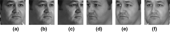
Example of cropped pose view face images in database of a + 15°, b + 30°, c + 45°, d − 45°, e − 30°, and f − 15°
-
2.
Pose and Frontal Face Shape Database. The pose and frontal face shape database is used as a reference to find the nearest frontal face shape according to the pose-view angle obtained at the process of facial landmark extraction and pre-processing. The frontal face shapes are canonical face-shape templates initially selected as representative faces in the training process. As shown in Fig. 5, each record in the database contains selected representative face shapes, and each field of representative canonical face shape template (A, B, C, …, n) includes its corresponding frontal face shape template. For example, Template B contains 6 pose views and 1 frontal view shape. When the pose-view angle is found, the nearest pose-view face shape is then selected, and its corresponding frontal face shape is used from this database.
Fig. 5 
Example of pose and frontal face shapes in database of a + 15°, b + 30°, c + 45°, d − 15°, e − 30°, and f − 45°
-
3.
Virtual Frontal Face Database. The virtual frontal face database consists of face-shape templates as a record, and identified persons as the field is used to identify a person by searching the closest face in the comparing with a frontal face which is warped by input face texture with selected face-shape template. An example of the database is shown in Fig. 6 where there are \(n\) face-shape templates and \(m\) persons in the database. Each person’s face appears in all \(n\) templates of the database.
Fig. 6 
Virtual frontal face images in the database. Here we keep n templates for m persons


4.2 Facial Landmark Extraction and Preprocessing Process
In the process of facial landmark extraction and preprocessing, a face with pose view in the range of ± 45° angle is input for marking landmarks based on a landmark extraction algorithm [23,24,25], and then cropping to get a pose-view face. As shown in Fig. 7, an input face image is cropped in the rectangle shape covering from eyebrow to chin, and its landmarks are extracted into 68 points. The cropped face is utilized in the next process for pose-view angle finding. The landmarks are employed in template matching to find the best frontal face shape.

Sample face input with 68 facial landmarks (FS) extracted including eyebrows, eyes, nose, mouth, and face shape
4.3 Pose-View Angle Finding Process
The cropped pose-view face image is used to find the pose-view angle by referring to the trained pose-view face images in the database. Currently, there are many classification tools to achieve this. This paper employs the deep learning with multiclass SVM [26, 27] as a classifier for finding pose-view angle, given its success rate.
4.4 Nearest Frontal Face Shape Determination Process
The pose-view angle found and the landmarks that represent face-shape are used to get the frontal-view face shape in the process of nearest frontal face shape determination. The database shown in Fig. 5 is searched in order to find the face shape template with the best match. The corresponding frontal face shape is also reported for use in the warping step. Since it is hard to provide face templates to cover all possible faces, we propose to set up to digitize all pose views for a set of canonical templates which are believed to cover all faces. In the determination of the nearest pose-view face-shape template, Euclidean distance error is calculated by the following equations.
where \(FS_{pv}\) is xy-coordinate \(\{ xy_{1} ,xy_{2} , \ldots ,xy_{z} \}\) of face shape landmarks (Fig. 7 shows an example with 68 points) at pose view and \(pv\) is the set of pose views \(\{ + 15^{ \circ } , + 30^{ \circ } , + 45^{ \circ } , - 15^{ \circ } , - 30^{ \circ } , - 45^{ \circ } \}\), \(i\) is a number of pose face shapes in the database, \(E\_FS_{pv}\) is Euclidean distance error of coordinate of face shape landmarks at pose view estimated, and \(E\_FS_{pv,nearest}\) is an error of the nearest pose shape matched.
Finally, the frontal view face-shape is determined by the following equation.
where \(E\_FS_{pv,1} ,\,\,E\_FS_{pv,2} , \ldots ,E\_FS_{pv,n}\) are Euclidean distance errors of coordinate of face shape landmarks at pose view estimated for all \(n\) face-shape templates,\(FS_{frontal,1} ,\,\,FS_{frontal,2} , \ldots ,FS_{frontal,n}\) are xy-coordinates of frontal face shape landmarks for all \(n\) face-shape templates, and \(FS_{frontal,nearest}\) is face shape landmarks for the nearest frontal face shape.
The obtained frontal-view face shape is then warped to get a synthesized frontal face image by textures extracted from input pose-view face image. Here we use the piecewise affine warping method (PAW) [28] to achieve texture warping.
4.5 Enhancement of Synthesized Frontal Face Process
Distortion normally occurs in the occluded side (left or right) of the synthesized frontal face. We propose to enhance it by mixing intensities of pixels in corresponding regions of left/right side of face. Since the non-occluded side is considered to be more reliable than occluded side and the pose-view angle is proportional to the texture distortion level, the weight of non-occluded side term should be bigger than the occluded one depending on the pose-view angle. This can be converted into an equation as follows:
where a is the weight of non-occluded side, b is the weight of occluded side, \(pv\) is pose view found, \(SFF_{Enhance}\) is synthesized frontal face image for a full face, \(SFF_{R}\) is synthesized frontal face image for right face side, and \(SFF_{L}\) is synthesized frontal face image for left face side. Figure 8 illustrates parameters to enhance the synthesized frontal face.

Parameters to enhance the synthesized frontal face
The mixed textures by the mentioned equation normally may not be smooth, especially in the middle borders. Thus, a smoothing process by the following equation should be performed as post-processing:
where \(middle \pm w\) is pixel width range from middle image position; for example \(a = 10\), and s is average filter \(s \times s\) pixels.
In fact, it is hard to determine a rigid rule for setting weights of occluded and non-occluded sides due to a variety of possible samples. Thus, pre-testing is recommended and subjective adjustment based on samples becomes inevitable. A sample of weights determination is shown below.
Here, \(t_{1} ,t_{2} ,t_{3} ,t_{4} ,t_{5} ,\,and\,t_{6}\) are the ratios of the synthesized frontal face image intensity for both face sides such that \(t_{1} + t_{2} = 1.0,\,\,t_{3} + t_{4} = 1.0\), and \(t_{5} + t_{6} = 1.0\). For example, say \(t_{1} = 0.3\) and \(t_{2} = 0.7\) for left side (\(SFF_{L}\)) with no-occlusion area and left side (\(SFF_{R}\)) with some occlusion area in case of +15° pose view estimated, say \(t_{3} = 0.5\) and \(t_{4} = 0.5\) for left side (\(SFF_{L}\)) with no-occlusion area and left side (\(SFF_{R}\)) with some occlusion area in case of + 30° pose view estimated, and say \(t_{5} = 0.7\) and \(t_{6} = 0.3\) for left side (\(SFF_{L}\)) with no-occlusion area and left side (\(SFF_{R}\)) with some occlusion area in case of + 45° pose view estimated. On the other hand, it uses \(t_{1} ,t_{2} ,t_{3} ,t_{4} ,t_{5} ,\,and\,t_{6}\) ratios as the same mentioned above but a different side of pose view face.
The enhanced synthesized frontal face image is finally classified based on the database of virtual frontal face database (Fig. 6) where the closest face would be selected among face images in the determined template. As a result, this classified face image identifies the person.
4.6 Face Recognition / Person Identification
In face recogniton or person identification, we employ 3 well-known face recognition approaches including local Gabor binary pattern (LGBP) [29], principal computer analysis (PCA) [30], and local binary pattern (LBP) [31]. There are many algorithms that work well to recognize face humam images, including PCA [30], LBP [31], LGBP [29], LDA [1], ICA [1], genetic algorithm (GA) [32], fuzzy differential equations [33], etc. We recommend using LGBP for 2D pose-invariant face recognition using single frontal-view face database and our enhanced synthesized frontal face method. The LGBP approach combines Gabor filters with LBP. This approach defined as histogram interaction is used to measure the face image similarity of different histograms between probe and gallery images. In the final matching, we use Euclidean distance to measure the similarity of histograms to identify the person in the probe face image.
5 Experiments and Experimental Results
We have evaluated the performance of our proposed method by using the enhanced synthesized frontal face image to identify a person from frontal face images in the database. In this paper, we use the popular pose view face databases CMU Multi-PIE [21] and CMU PIE [34] for our experiments. We set up the experiments with same protocol as methods [10, 17]. The experimental results and examples are described below in this section.
In the experimental set-up, the CMU Multi-PIE face database which contains face images of 337 persons across the four recording sessions. Face images of the first 200 persons are used for training to create cropped pose view face, pose face shape, and frontal face shape databases described in section III as part of the database creation process. Moreover, the face images of the 137 remaining persons are employed for the testing process. Gallery frontal face database is collected from face images of the 137 remaining persons from the earliest recording sessions. For testing set, we employed the pose-view face images of the 137 remaining persons for ± 45°, ± 30°, and ± 15° pose views. We normalized the cropped pose-view face, pose face shape, and frontal face with size of 90 × 90 pixels with the grayscale color images. As another CMU PIE face database, we test with face images for all 68 persons with pose-views ± 22.5° and ± 45° angles by using training data from CMU Multi-PIE database instead.
5.1 Face Recognition Performance
We have tried some current well-known classification tools such as local Gabor binary pattern (LGBP) [29], principal component analysis (PCA) [30], and local binary pattern (LBP) [31] for face recognition. We used the popular CMU Multi-PIE face database with 137 remaining persons as described in the experiment set-up section. The gallery database is the frontal-view face image and testing set is pose-view face images with range ± 45°, ± 30°, and ± 15° angles. We found that the LGBP approach accomplished the best accuracy compared with other existing tools as shown in Table 1. In comparison with conventional methods as shown in Table 2, although our proposed method including use LGBP classification does not come up as the best one, it achieves accuracy in the same levels with the conventional method, while requiring only a frontal face image database.
As another result of our proposed method, we measure the performance by using CMU PIE face database. We then determined the accuracy of LGBP face recognition when using our enhanced synthesized frontal face image with only normalized face image and the LLR method [27]. This is shown in Table 3.
5.2 Example of Enhanced Synthesized Frontal Face Image
Examples of our enhanced synthesized frontal face images that are converted from pose view image into the nearest face shape matched are shown in Tables 4 and 5 for the CMU Multi-PIE, and CMU PIE face database, respectively. Our enhanced synthesized frontal face image provides a better texture similarity to the virtual face database. Thus, our approach results in a significant improvement in accuracy.
6 Discussion
This paper proposes a method of 2D pose-invariant face recognition using a frontal-view face database. First of all, the method detects pose-view angle, then employs the angle to find the face-shape template by template matching, and the textures of face image input to the frontal face of the matched template. Also, the frontal face which is distorted by occlusion in pose-view is enhanced by mixing the intensities of the occluded part with parts from the visible side, assuming facial symmetry. The experimental results were done on CMU Multi-PIE face database as shown in Table 2. Our proposed method achieves acceptable accuracy similar to conventional methods, while our proposed method requires a single frontal-view face database as gallery, which is a big advantage.
In comparison among existing classification tools, Table 1 shows LGBP currently performs with very high accuracy. However, users may consider other face recognition algorithms that suit their needs. Besides the conventional database of CMU Multi-PIE, we also tried experiments on the CMU PIE database with results shown in Table 3. We found that our proposed method is better than the conventional method.
In error analysis of our proposed method as shown in Fig. 9, errors are grouped by their causes into three cases including expression, eye-glasses, and shading. These are actually out of the scope of this paper, but such errors can be solved by methods [22, 35]. This will be our future works to add to our face recognition system.

Sample error analysis. Our algorithm fails when there are images with a expression, b eye-glasses, and c shading
7 Conclusion
Pose-invariant face recognition is still a challenging field in face recognition. To be practical on should assume the gallery contains only frontal-view images. This paper proposes a method of 2D pose-invariant face recognition by using a frontal-view gallery. In the algorithm, facial landmarks are first extracted and used to normalize the face images as part of preprocessing. Next, the pose-view angle is determined, and it is used to turn pose-view face shape to frontal view by template matching of the nearest face shape with some pose-view face shape provided in advance. The frontal-view face shape of the matched pose-view face template is subsequently warped by face textures from input pose-view face image, and the occluded face side (left or right) is enhanced by mixing intensities between both left and right sides in an appropriate ratio based on a pose-view angle. This will enhance some of the distortion in areas with high self-occlusion. We finally get an enhanced synthesized frontal face image from the proposed method. We then look at the face recognition accuracy by using the enhanced synthesized frontal-view face to search for the nearest face in the virtual frontal face database to report the identified person. The performance of the proposed method as tested on CMU Multi-PIE face database reveals good accuracy, with results similar to conventional methods while only requiring a single frontal-view face database.
References
Zhao, W., Chellappa, R., Phillips, P. J., & Rosenfeld, A. (2003). Face recognition: A literature survey. ACM Computing Surveys, 35(4), 399–458.
Hassaballah, M., & Aly, S. (2015). Face recognition: Challenges, achievements and future directions. IET Computer Vision, 9(4), 614–626.
Ding, C., & Tao, D. (2016). A comprehensive survey on pose-invariant face recognition. ACM Transactions on Intelligent Systems and Technology, 7(3), 37:1–37:42.
Blanz, V., & Vetter, T. (2003). Face recognition based on fitting a 3d morphable model. IEEE Transactions on Pattern Analysis and Machine Intelligence, 5(9), 1063–1074.
Lee, M. W., & Ranganath, S. (2003). Pose-invariant face recognition using a 3d deformable model. Pattern Recognition, 36(8), 835–1846.
Jiang, D., Hu, Y., Yan, S., Zhang, L., Zhang, H., & Gao, W. (2005). Efficient 3d reconstruction for face recognition. Pattern Recognition, 38(6), 787–798.
Asthana, A., Marks, T. K., Jones, M. J., Tieu, K. H., & Rohith, M. (2011). Fully automatic pose invariant face recognition via 3d pose normalization. In IEEE conference on computer vision and pattern recognition, pp. 937–944.
Yi, D., Lei, Z., & Li, S. Z. (2013). Towards pose robust face recognition. In IEEE conference on computer vision and pattern recognition, pp. 3539–3545.
Ding, C., Xu, C., & Tao, D. (2015). Multi-task pose-invariant face recognition. IEEE Transactions on Image Processing, 24(3), 980–993.
Ding, C., & Tao, D. (2017). Pose-invariant face recognition with homography-based normalization. Pattern Recognition, 66, 144–152.
Gross, R., Mattews, I., & Baker, S. (2004). Appearance-based face recognition and light-fields. IEEE Transactions on Pattern Analysis and Machine Intelligence, 26(4), 449–465.
Chai, X., Shan, S., & Chen, X. (2007). Locally linear regression for pose-invariant face recognition. IEEE Transactions on Image Processing, 16(7), 1716–1725.
Ashraf, A. B., Lucey, S., & Chen, T. (2008). Learning patch correspondences for improved viewpoint invariant face recognition. In IEEE conference on computer vision and pattern recognition, pp. 1–8.
Gao, H., Ekenel, H. K., & Stiefelhagen, R. (2009). Pose normalization for local appearance based face recognition. In International conference on advances in biometrics, pp. 32–41.
Ho, H. T., & Chellappa, R. (2013). Pose-invariant face recognition using Markov random fields. IEEE Transactions on Image Processing, 22(4), 1573–1584.
Kan, M., Shan, S., Chang, H., & Chen, X. (2014). Stacked progressive auto-encoders (SPAE) for face recognition across poses. In IEEE conference on computer vision and pattern recognition.
Zhu, Z., Luo, P., Wang, X., & Tang, X. (2013). Deep learning identity-preserving face space. In IEEE conference on computer vision and pattern recognition, pp. 113–120.
Zhang, Y., Shao, M., Wong, E. K., & Fu, Y. (2013). Random faces guided sparse many-to-one encoder for pose-invariant face recognition. In IEEE conference on computer vision and pattern recognition, pp. 2416–2423.
Yim, J., Jung, H., Yoo, B., Choi, C., Park, D., & Kim, J. (2015). Rotating your face using multitask deep neural network. In IEEE conference on computer vision and pattern recognition, pp. 676–684.
Gentle, J. E. (2007). Matrix transformations and factorizations. In Matrix algebra: Theory, computations, and applications in statistics. Springer. ISBN 9780387708737.
Gross, R., Matthews, I., Cohn, J., Kanade, T., & Baker, S. (2009). Multi-PIE. Image and Vision Computing, 28, 807–813.
Petpairote, C., Madarasmi, S., & Chamnongthai, K. (2017). Personalised-face neutralisation using best-matched face shape with a neutral-face database. IET Computer Vision. https://doi.org/10.1049/iet-cvi.2017.0352.
Cootes, T. F., Edwards, G. J., & Taylor, C. J. (2001). Active appearance models. IEEE Transactions on Pattern Analysis and Machine Intelligence, 23(6), 681–685.
Cristinacce, D., & Cootes, T. F. (2006). Feature detection and tracking with constrained local models. In British Machine Vision Conference, Vol. 3, pp. 929–938.
Zhu, X., & Ramanan, D. (2012). Face detection, pose estimation, and landmark localization in the wild. In IEEE conference on computer vision and pattern recognition. 10.1109/CVPR.2012.6248014.
Parkhi, O. M., Vedaldi, A., & Zisserman, A. (2015). Deep face recognition. In British Machine Vision Conference, pp. 1–12.
Simonyan, K., & Zisserman, A. (2014). Very deep convolution networks for large-scale image recognition. arXiv:1409.1556.
Matthews, I., & Baker, S. (2004). Active appearance models revisited. International Journal of Computer Vision, 60(2), 135–164.
Zhang, W., Shan, S., Gao, W., Chen, X., & Zhang, H. (2005). Local Gabor binary pattern histogram sequence (LGBPHS): A novel non-statistical model for face representation and recognition. In IEEE international conference on computer vision. https://doi.org/10.1109/iccv.2005.147.
Turk, M., & Pentland, A. (1991). Eigenfaces for recognition. Journal of Cognitive Neuroscience, 3(1), 71–86.
Timo, A., Abdenour, H., & Matti, P. (2004). Face recognition with local binary patterns. In European Conference on computer vision, pp. 469–481.
Arqub, O. A., & Abo-Hammour, Z. (2014). Numerical solution of systems of second-order boundary value problems using continuous genetic algorithm. Information Sciences, 279, 396–415.
Arqub, O. A., Smadi, M. A., Momani, S., & Hayat, T. (2016). Numerical solutions of fuzzy differential equations using reproducing kernel Hilbert space method. Soft Computing, 20(8), 3283–3302.
Sim, T., Baker, S., & Bsat, M. (2002). The CMU pose, illumination, and expression (PIE) database. In International conference auto face and gesture recognition, Washington, DC, pp. 46–51.
Lin, J., Ming, J., & Crookes, D. (2011). Robust face recognition with partial occlusion, illumination variation and limited training data by optimal feature selection. IET Computer Vision, 5(1), 23–32.
Kafai, M., An, L., & Bhanu, B. (2014). Reference face graph for face recognition. IEEE Transactions on Information Forensics and Security, 9(12), 2132–2143.
Acknowledgements
The financial support provided by the Thailand Research Fund through the Royal Golden Jubilee Ph.D. Program (Grant No. PHD/0056/2551), and the King Mongkut’s University of Technology Thonburi are gratefully acknowledged.
Author information
Authors and Affiliations
Corresponding author
Additional information
Publisher's Note
Springer Nature remains neutral with regard to jurisdictional claims in published maps and institutional affiliations.
Rights and permissions
About this article

Cite this article
Petpairote, C., Madarasmi, S. & Chamnongthai, K. 2D Pose-Invariant Face Recognition Using Single Frontal-View Face Database. Wireless Pers Commun 118, 2015–2031 (2021). https://doi.org/10.1007/s11277-020-07063-1
Published:
Issue Date:
DOI: https://doi.org/10.1007/s11277-020-07063-1