
Abstract
Heat transfer property of textile materials has always been the major concern when the comfort properties of clothing are characterized. A three-layer branching-structured biomimic woven fabric was promoted. The steady-state heat transfer performance of the fabric was analyzed using finite element method. With specification of initial and boundary conditions, thermal flux distribution of the biomimic fabric was simulated. The predicted effective thermal conductivity agreed well with the experimental result. Accordingly, the heat transfer properties of the fabric can be further optimized with assistant of this model.
Introduction
As warm retention property is one of the most important factors for clothing comfort, thermal transfer mechanism analysis has been widely recognized as an effective method for understanding the thermal comfort of clothing during wear [1–3]. Ismail et al. [4] gave a theoretical model to predict the thermal conductivity of plain woven fabric based on the fabric geometrical structure. Kothari and Bhattacharjee [5] promoted a geometry model to predict the thermal resistance of fabrics and simulated the convective heat transfer of the fabric using the computational fluid dynamics (CFD) technology. Zhu et al. [6] obtained the effective thermal conductivity of random fibrous materials using fractal analysis. Fan and He [3] investigated the thermal behavior of fabric using the fractal derivative method based on the multi-scale profile of textile fabrics.
Theoretical study of heat transfer of textiles usually established a series of governing equations based on the energy conservation law to depict the heat transfer process in fabrics [7–10]. Generally, these governing equations were built on the basis of certain assumptions and could be solved by giving the initial and boundary conditions. For most of the case, it is extremely difficult to obtain a numerical solution using conventional calculation method because of the complexity of these practical problems.
Finite element analysis, considering as an effective tool with advantages such as simplicity, celerity and veracity, is very suitable for solving the above problems. Sun et al. [11] analyzed the factors influencing heat transfer of the fabrics systematically by using the finite element analysis software; Gong et al. [12] established a one-dimensional heat transfer model to simulate and predict the thermal protection property of textile fabrics using ANSYS software. Siddiqui and Sun [13] predicted the effective thermal conductivity and thermal resistance of the woven fabric by using finite element method based on the actual parametric value of the fabric.
In this presentation, we promote a biomimic multilayer warm retention woolen fabric with excellent moisture management property. A finite element model is developed to predict the thermal conductive behavior of the fabric, and the model is validated by experimental results.
Weave design
It has been well recognized that the structure of fiber and the assembly of fiber in fabric by spinning and weaving are crucial to the fabric properties [14–20]. Fan et al. [21] suggested a plant-structured multilayer fabric with fast initial water absorption and water transmission properties. Our previous research work has also proved that the plant-structured fabric had excellent warm retention property, which might be due to the relatively loose compact structure of the fabric with hierarchic air pores assembly [22]. This fabric is therefore ideal for developing functional warm retention cloth since the excellent water and moisture management properties of fabric are critical in keeping the skin dry and insuring the warm retention performance of clothing. However, the fabric structure of the plant-structured multilayer fabric was so complex that it has to be manufactured on a jacquard loom. In this presentation, we suggest a novel biomimic multilayer fabric that can be completed on an ordinary loom with 12 healds. The warp yarn system, rather than weft system in this fabric, was chosen to construct the tree-shaped branches, and the weave structure of the fabric’s bottom layer was simplified as well.
As shown in Fig. 1, the novel biomimic fabric consists of three group of warp yarns, which have the same movement rule but regularly dislocated among each other. Figure 2 depicts the movement rule of one group warp yarns in the biomimic fabric. The continuous warp yarns at the fabric bottom layer do not interlace with the weft yarns but exist as the combined short floats. The floats gradually separate into pairs and single yarns in the middle and top fabric layers to interlace with weft yarns, forming 2/2 matt structure and plain structure, respectively. Thus, the warp yarns form a continuous multi-branch structure in the biomimic fabric, which can effectively transport the water or moisture from the bottom layer to the top layer and accelerate the evaporation of water on the fabric surface.

Schematic diagram of the biomimic fabric

Movement rule of one group of warp yarns in fabric
The novel biomimic fabric not only has a better warm retention property, but also has an improved wet management property comparing with the ordinary fabrics. The reason may be that the special fabric bottom layer, which is fully covered by short warp yarn floats, doubles the water absorption area of the fabric. Additionally, the number of warp yarns in a fabric repeat unit is reduced from 24 to 12 yarns, and the number of weft yarns is reduced from 72 to 36 yarns, which reduced the length of transport paths by half.
Finite element model
-
1.
Unit cell
The geometry of woven fabric can be characterized completely by its smallest repeat unit. In order to avoid complex calculation, we choose half of the fabric intact repeat as the representative unit cell for heat transfer simulation. The unit cell is a cuboid space occupied by half of the fabric repeat and the air filling in the free space between yarns. The half fabric repeat is made up by 6 warp yarns and 36 weft yarns. Interlacing pattern of the warp yarns and the weft yarns is illustrated in Fig. 3, and the geometric parameter of the half fabric repeat unit is shown in Table 1. The air portion of the unit cell can be obtained by subtracting the overlapping space occupied by yarns from the same cuboid occupied by air, and this operation is finished by Boolean operation. Thus, the compound physical model is established.
Fig. 3 
Physical model of unit cell
Table 1 Geometric parameter of the unit cell -
2.
Mesh generation
The above physical model of the fabric unit cell was then imported into ANSYS Workbench. The volume occupied by yarn and air in the unit cell is meshed separately with different mesh density. The meshed unit cell consists of 186,040 nodes and 135,919 elements (see Fig. 4).
Fig. 4 
Meshed unit cell with air–fluid matrix
-
3.
Boundary condition
For one-dimensional steady-state heat transfer analysis across the thickness direction of the fabric, the boundary conditions are the specified temperature values on both side of the fabric. The temperature of the outer fabric surface was set as the external environmental temperature 22 °C (295 K), while the temperature of the inner fabric surface was set as the skin temperature 35 °C (308 K). Moreover, the free convective heat exchange occured on the outer surface of the fabric with convective heat transfer coefficient 10 W m−1 K−1. After setting the thermal conductivity of yarn and air, which are 0.046 and 0.024 W m−1 K−1, respectively, we obtained the heat transfer simulation results of the fabric’s unit cell.
-
4.
Numerical results and analysis
Temperature distribution diagrams of the unit cell and the yarns are shown in Fig. 5a, b. It can be found that temperature decreases evenly along the thickness direction of the unit cell. The inner surface of the fabric has the highest temperature, while the outer surface has the lowest temperature. Figure 5b also shows that it was the continuous warp yarn moving back and forth between the top and bottom layers of the fabric that provides a thermal transfer path for the fabric. Furthermore, the branching structure of warp yarn system can enlarge the thermal transfer area, which tends to enhance the thermal dissipation on the top layer of the biomimic fabric. However, the yarn volume fraction of biomimic fabric just occupies about 10 %, and the thermal dissipation by the continuous warp yarn system is ignorable.
Fig. 5 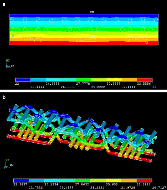
a Temperature (°C) distribution of the unit cell; b temperature distribution (°C) of the biomimic fabric’s half repeat unit
Heat flux diagram of the unit cell as shown in Fig. 6 releases that heat flux of yarns is larger compared with that of the air in the same fabric layer, indicating that the yarn phase serves as the main thermal conductor in the fabric. Thermal gradient distribution of the unit cell shown in Fig. 7 suggests that the thermal gradient of yarn is relatively small since it has a better heat-conducting property. In contrast, the air phase with smaller thermal conductivity shows larger thermal gradient. It should be noted that the thermal gradient of the outer surface of fabric is large. The reason might be that the free convection facilitates a quick thermal exchange on the outer surface of fabric.
Fig. 6 
Heat flux (W m−2) distribution of the unit cell
Fig. 7 
Temperature gradient (°C m−1) of the unit cell
-
5.
Effective thermal conductivity of the biomimic fabric
The effective thermal conductivity K y (W m−1 K−1) in the y direction of the biomimic fabric can be calculated by using the following equation:
$$ K_{y} = Q_{y} \frac{h}{{\Delta T_{y} }} $$(1)where h is the fabric thickness (m), which is given in the physical model of the fabric unit. ΔT y is the temperature difference between the top and the bottom surface of fabric (K), which is defined by the boundary conditions. Q is the heat flux through the physical model of the fabric unit (W m−2), which is obtained by summing up the nodal values of the heat flux of all nodes on the fabric surface.
The effective thermal conductivity of the biomimic fabric was calculated to be 0.0307 W m−1 K−1 by submitting the simulation result and the geometric parameter of the unit cell (see Table 1) into Eq. (1). The predicted result indicated that the biomimic fabric has a good warm retention property.


Model validation
To evaluate the validity of the simulated result, we prepared a biomimic fabric using 25tex/2 (0.24 mm in diameter) wool yarn. The fabric structural parameters are listed in Table 2. Thermal resistance of the prepared biomimic fabric was tested using a M925 SDL sweating guarded hotplate in standard condition. The thermal conductivity of the prepared biomimic fabric is calculated to be 0.0304 W m−1 K−1. The predicted value agrees well with the experimental value, suggesting that the finite element model can successfully predict the thermal conductivity of the fabric.
Conclusions
In this study, the steady-state heat transfer performance of a multilayer biomimic fabric was investigated by finite element method. Temperature distribution and heat flux distribution were obtained by the finite element model. The effective thermal conductivity was calculated based on the simulated result. A woolen fabric was prepared, and the fabric’s thermal conductivity derived from simulated result is very close to the experimental result, suggesting that the validated finite element model can give accurate results.
References
Song W, Yu W. Heat transfer through fibrous assemblies by fractal method. J Therm Anal Calorim. 2012;110:897–905.
Qian X, Fan J. A quasi-physical model for predicting the thermal insulation and moisture vapour resistance of clothing. Appl Ergon. 2009;40:577–90.
Fan J, He JH. Biomimic design of multi-scale fabric with efficient heat transfer property. Therm Sci. 2012;16:1349–52.
Ismail MI, Ammar ASA, EI-Okeily M. Heat transfer through textile fabrics: mathematical model. Appl Math Model. 1988;12:434–40.
Kothar VK, Bhattacharjee D. Prediction of thermal resistance of woven fabrics. Part I: mathematical model. J Text Inst. 2008;99:421–32.
Zhu F, Cui S, Gu B. Fractal analysis for effective thermal conductivity of random fibrous porous materials. Phys Lett A. 2010;374:4411–4.
Zhu QY, Xie MH, Yang J, Li Y. A fractal model for the coupled heat and mass transfer in porous fibrous media. Int J Heat Mass Transf. 2011;54:1400–9.
Ran XJ, Zhu QY, Li Y. Investigation on heat and mass transfer in 3D woven fibrous material. Int J Heat Mass Transf. 2011;54:3575–86.
Min K, Son Y, Kim C, Lee Y, Hong K. Heat and moisture transfer from skin to environment through fabrics: a mathematical model. Int J Heat Mass Transf. 2007;50:5292–304.
Fan J, Wen X. Modeling heat and moisture transfer through fibrous insulation with phase change and mobile condensates. Int J Heat Mass Transf. 2002;45:4045–55.
Sun YC, Feng XW, Liu CY. Application of finite element method in analysis of heat transfer through textile fabrics. J Dong Hua Univ. 2006;32:50–3.
Gong YR, Zhang X, Mao ZP. Numerical simulation on thermal protection properties of textile materials. J Dong Hua Univ. 2010;36:115–7.
Siddiqui MOR, Sun D. Finite element analysis of thermal conductivity and thermal resistance behaviour of woven fabric. Comput Mater Sci. 2013;75:45–51.
Lizák P, Legerská J, Mojumdar SC. Influence of cross profile of PE fibers on thermal properties of materials. J Therm Anal Calorim. 2013;112:1013–8.
Lizák P, Legerská J, Mojumdar SC. Influence of knitted structures on heat transfer. J Therm Anal Calorim. 2013;112:1089–94.
Bagherzadeh R, Gorji M, Latifi M, Payvandy P, Kong LX. Evolution of moisture management behavior of high-wicking 3D warp knitted spacer fabrics. Fibers Polym. 2012;13:529–34.
Bedek G, Salaun F, Martinkovska Z, Devaux E, Dupont D. Evaluation of thermal and moisture management properties on knitted fabrics and comparison with a physiological model in warm conditions. Appl Ergon. 2011;42:792–800.
Majumdar A, Mukhopadhyay S, Yadav R. Thermal properties of knitted fabrics made from cotton and regenerated bamboo cellulosic fibres. Int J Therm Sci. 2010;49:2042–8.
Ozdil N, Marmaralı A, Kretzschmar SD. Effect of yarn properties on thermal comfort of knitted fabrics. Int J Therm Sci. 2007;46:1318–22.
Legerská J, Lizák P, Murárová A, Mojumdar SC. Thermal analysis of the polyester profiled fiber. J Therm Anal Calorim. 2013;112:1019–23.
Fan JT, Sarkar MK, Szeto YC, Tao XM. Plant structured textile fabrics. Mater Lett 2007;61:561–65.
Fan J, Zhu N, Cheng Q. Effective thermal conductivity of complicated hierarchic multilayer fabric. Therm Sci. 2014;18:1613–8.
Acknowledgements
The work is supported by National Natural Science Foundation of China under Grants No. 51203114, Special Program of China Postdoctoral Science Foundation Grant No. 2013T60559, China Postdoctoral Science Foundation under Grants No. 2012M521122, Postdoctoral Science Foundation Jiangsu Province Grant No. 1301151C, Natural Science Funds of Tianjin under Grant No. 12JCQNJC01500, program for New Century Excellent Talents in University under Grants No. NCET-12-1063.
Author information
Authors and Affiliations
Corresponding authors
Rights and permissions
About this article

Cite this article
Fan, J., Wang, Ll., Cheng, Q. et al. Thermal analysis of biomimic woven fabric based on finite element method. J Therm Anal Calorim 121, 737–742 (2015). https://doi.org/10.1007/s10973-015-4614-0
Received:
Accepted:
Published:
Issue Date:
DOI: https://doi.org/10.1007/s10973-015-4614-0