
Abstract
A new procedure for filamentary metal matrix composite processing is described here. It consists in running carbon-coated SiC filaments through a liquid titanium bath in levitation. The liquid metal/carbon interaction must be significant enough to enable filament wetting and sufficiently low to avoid composite embrittlement. To insure both requirements, different configurations of the initial ceramic filament can be used: (1) SiC(C) filament free of any other coating, (2) SiC(C) filament coated with a carbide obtained by reactive chemical vapour deposition (R-CVD), or (3) SiC(C) previously coated by a first metal layer. In order to choose the best conditions for developing the process, the different processing configurations were studied through modelling and numerical simulations of the filament/matrix interaction. The microstructure of the interfacial zone between filament and matrix was investigated through SEM and Auger electron spectroscopy (AES) analyses. The microstructure of the interfacial zone between filament and matrix was investigated through SEM and AES analyses. The results show that in comparison to the first processing configuration, the best way to obtain filamentary composite semi-products without excessive fibre/matrix interaction is to use the second configuration. However, the latter requires preliminary R-CVD operations, while the third configuration leads to moderate carbon embrittlement effect without requiring additional equipment.
Introduction
SiC-fibre-reinforced titanium matrix composites (TMC) are potential materials for high-temperature structural applications such as compressor bladed rings (blinks) in aircraft engines, links and other applications requiring high stiffness such as the examples of shafts in helicopter engines and landing gear proposed by Salzar [1] and Hooker and Doorbar [2]. However, the available processing methods for manufacturing TMC are too costly for the related gain in performance (Soumelidis et al. [3], Wei [4], Molliex et al. [5], Gao and Zhao [6], Cotterill and Bowen [7], Bobet et al. [8] and Thomas and Winstone [9]). Prior to hot compression of TMC parts, filament/matrix coupling must be performed through various methods which exhibit different disadvantages. The Foil-Fibre-Foil method described by Nicolaou et al. [10] and Hirose et al. [11] consists in the consolidation of alternately stacked layers of about 100-µm-thick metal foils and aligned ceramic filaments about 140 µm in diameter. The process requires a good formability of the matrix and often leads to poor reinforcement distribution. Plasma Spray coating of unidirectional layers of ceramic filaments as depicted by Mackay et al. [12] provides better reinforcement distribution in the matrix but the filaments are partially degraded by thermal shock and metal droplet/ceramic filament interaction. PVD methods which were particularly investigated by Leucht and Dudeck [13] enable very uniform reinforcement distributions. However, in the case of electron beam evaporation and deposition technique (EBED), the composition of the matrix is not easily controlled and the kinetics of deposition is rather low. As for using the powder route through a method of filament coating as proposed by Sanguinetti et al. [14, 15], it is difficult to adjust the processing parameters to insure homogeneous reinforcement distribution and good matrix densification by hot pressing at temperature and pressure moderate enough to prevent any chemical and mechanical filament degradation.
Alongside these traditional methods of manufacturing, a new process based on the liquid route, resulting in a filamentary composite semi-product has been proposed by Dambrine et al. [16]. The process consists in running SiC filaments through a liquid titanium alloy bath at very high speeds to prevent excessive chemical interaction between the protective carbon coating of SiC filaments and the highly reactive liquid Ti. Indeed, previously, Toloui [17], Cooke et al. [18] as well as Warrier and Lin [19] with infrared heating attempted to use the liquid route to process TMC. They have shown how fast the ceramic filament/liquid metal coupling must be to maintain the potential reinforcement performance. Although the proposed method is very fast as the filament running speed is higher than 1 m s−1, the carbon transfer from C-coated SiC filaments has to be monitored closely, firstly in order to prevent the reinforcement degradation and secondly prevent Ti matrix embrittlement. As a matter of fact and as shown by Duda et al. [20], the liquid Ti/C coating interaction during the filamentary composite processing gives rise to TiC1−x formation both at the filament/matrix interface and within the Ti coating surrounding the filament. On the other hand, Feigenblum [21] showed that the presence of a very thin carbide layer on the carbon-coated filament is required for wetting the reinforcement with the liquid titanium and covering it with a concentric titanium coating.
The objective of the present contribution is to depict the processing conditions and understand the mechanisms correlating the processing parameters and the resulting filamentary composite microstructures through the exploitation of numerous numerical tests. Indeed, the same investigation through experimental tests would be technically very difficult and, above all, too expensive for a preliminary approach of the process. The numerical investigation we proposed elsewhere is based on a thermo-metallurgical model [22]. Only a small number of experiments allowed the feasibility of the process to be shown and the modelling to be validated. If attention is focused on carbon transfer from the reinforcement towards the matrix, the use of the related numerical tool allows the influence of the processing conditions on filamentary composite microstructures to be highlighted. As a matter of fact, the significance of carbon transfer can be considered as a performance indicator of the filamentary composite as it controls both matrix embrittlement and reinforcement degradation.
Description and modelling of the process
TMC components
Although various kinds of ceramic filaments and metal alloys could be combined with the proposed high-speed liquid coating process, the latter has been focused on two similar types of SiC filamentary reinforcement and on one titanium-based alloy matrix (Ti 6Al 2Sn 4Zr 2Mo), the microstructure of which is near alpha (90 %) (Smith et al. [23], Ward et al. [24]). Both ceramic filaments illustrated in Fig. 1 are constituted of three components: (1) a carbon core for the SCS6 filament (case a) or a tungsten core for a new experimental SiC filament (case b), (2) a surrounding SiC deposit and finally (3) a protective 4-µm-thick coating of C/SiC mixture in the case of the SCS6 filament (a) or quasi pure pyrolytic carbon in the case of the experimental filament (b). In both cases, the reinforcement/matrix coupling leads to a direct contact between the liquid Ti-based matrix and the carbon coating of the SiC(C) ceramic filament.

SEM micrographs of SiC filaments characterized by a Carbon core and C/SiC coating, b W core and C coating
Main features of the high-speed liquid coating process
With the help of the equipment illustrated in Fig. 2, the high-speed liquid coating process can be described by the following steps performed in a tower chamber under vacuum:

High-speed metal coating apparatus
-
(1)
the 148-µm-diameter ceramic filament at high running speed (several metres per second) is introduced quickly into the bath of molten metal in electromagnetic levitation, through one of the notches designed in the RF induction heating water cooled crucible,
-
(2)
after an incubation time of a few milliseconds, the interaction between the carbon-coated filament and the liquid bath may be sufficient to induce filament wetting by the molten metal, thanks to the formation of a carbide interphase at the liquid metal/C coating interface,
-
(3)
then, when the filament comes out of the liquid bath, its wetting enables a liquid metal layer to cover the filament with a thickness which is greatly dependant on the filament running speed V as detailed elsewhere (De Ryck and Quere [25], Feigenblum [21]). Up to a speed threshold of a few metres per second, the thickness of the metal coating increases slightly due to the speed. However, for these rather low speeds, the coating thickness remains too slight (a few microns) to give rise to sufficient metal matrix volume fractions in the related composites and to avoid contact between reinforcing filaments after hot compression of filamentary composite arrangements (Fig. 3c). Above the speed threshold, the thickness of the metal coating can reach a few tens of microns leading to reinforcement volume fractions of about 30–35 % but it decreases slightly when the filament running speed is increased. This evolution in thickness enables the reinforcement volume fraction to be adjusted, providing it is possible to perform metal coating at very high speed which requires technological issues to be overcome.
Fig. 3 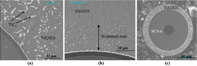
Microstructure of titanium base matrix obtained for various SiC/Ti filamentary composites and as presented by Duda [26]: a TiCx within bi-phased zone. b Width of bi-phased zone. c Thin Ti coating completely bi-phased
-
(4)
as soon as the filament comes out of the bath, the liquid metal coating is cooled by both radiation and forced convection characterized by a coefficient h and performed, thanks to a specific device which blows helium or argon through several small nozzles,
-
(5)
Finally, once the layer of the metal coating has solidified, the resulting filamentary composite is wound around a pulley.

In conclusion, the time of filament immersion in the liquid bath must be long enough to generate the formation of carbide required for filament wetting. However, the time must also be short enough to avoid excessive carbon transfer leading to reinforcement degradation and matrix embrittlement by Ti carbide formation in parts or the whole metal coating (Fig. 3).
Modelling and numerical simulation of the process
The description of the process modelling and related numerical tool based on the classical heat and mass diffusion equations was the objective of another contribution reported elsewhere [22]. However, in order to understand the present contribution, it is necessary to keep in mind the following assumptions:
-
(1)
the required simplification of reinforcement and matrix complexity has led the matrix to be considered as pure titanium and the reinforcement to be considered as pure carbon-coated filaments,
-
(2)
the displacement speed of the liquid metal layer coating the filament is the same as the speed of the filament,
-
(3)
the carbon transfer from the filament coating towards the liquid metal matrix is the only mass transfer considered in the present study,
-
(4)
consequently, carbide is the only phase formed within the liquid metal,
-
(5)
before substantial carbide formation, the carbon transfer is controlled by the mechanism of dissociation of the carbon coating in contact with the liquid titanium. After that, it is controlled by carbon diffusion through the formed carbide layer. The transition between the two controlling mechanisms of carbon flow occurs when the C diffusion flow through the formed TiC1−x layer is lower than the C dissociation flow.
-
(6)
the phase equilibriums involved in the process can be related to the Ti/C phase diagram given by Massalski [27],
-
(7)
longitudinal heat and mass transfer is not taken into account owing to the high running speed of the filament,
-
(8)
the axisymmetry of the whole system enables the use of cylindrical coordinates to simulate the process,
-
(9)
the time is directly correlated to the longitudinal position of a considered filament section in the liquid bath.
The combination of the three previous assumptions allowed a 2D model to be used to perform the numerical simulation of the process.
More details related to the conditions of the numerical simulation (equations as well as initial and boundary conditions) and above all the validation of the modelling through some preliminary experiments were provided in [22].
Simulation of various processing configurations
The main issue to overcome for obtaining high performance SiC(C)/Ti filamentary composite semi-products is related to the interaction between filament C coating and liquid Ti.
On the one hand, for a given height of the Ti liquid bath, the filament running speed V must be sufficiently moderate (for instance, 1 m s−1) to allow filament wetting, thanks to a sufficient Ti/C contact time leading to carbide formation. If it is not the case, the Ti coating geometry cannot be correct giving rise to an exocentric matrix coating with respect to the reinforcement. On the other hand, the filament running speed must be high enough to prevent excessive C transfer into the matrix and to permit a sufficient Ti thickness e surrounding the ceramic filament, to be brought out of the Ti liquid bath as demonstrated by De Ryck and Quere [25].
In order to reduce expensive and time-consuming experimentation to highlight the importance of the main processing parameters (e, V, h), three processing configurations were simulated to evaluate their ability to render the previous requirements compatible.
-
(1)
The first configuration is related to the entry of C-coated SiC filaments (SiC(C)) free of any additional carbide into the liquid bath, that is to say, the use of the initial ceramic filaments illustrated in Fig. 1a.
-
(2)
The second case corresponds to the use of filaments previously coated with a TiC carbide layer before their entry into the molten Ti bath. Arvieu et al. [28] have shown that such a carbide coating can be obtained by R-CVD.
-
(3)
The third case is related to the use of filaments previously coated with a thin titanium layer of about 10–20 µm, developed thanks to a first run through the bath, that is to say filamentary composites obtained at low processing speeds. This insures filament wetting without expecting to bring a sufficient matrix thickness out of the Ti bath. The second run aims at obtaining suitable reinforcement volume fractions. In this case, initial filament is constituted by the basic C-coated SiC filament, the TiC layer formed during the first run and the related thin Ti alloy coating similar to the one illustrated in Fig. 3c.
After using the first configuration to show the influence of the main processing parameters on the carbon transfer, the three configurations were compared for the same matrix thickness of 50 µm surrounding the filaments. In all cases, the carbon transfer is considered as a quality indicator. The significance of carbon transfer is represented by the thickness of the TiC1−x layer formed at the filament/matrix interface and the width of the bi-phased Ti/TiC1−x alloy more or less surrounded by the mono-phased Ti-base alloy.
Results
For most numerical simulations, when the processing conditions are not specified, the filament running speed was V = 2 m s−1, the filament surrounding Ti thickness was \( e \) = 50 µm and the heat transfer coefficient characteristic of the cooling conditions was h = 300 W m−2 K−1.
Initial SiC filaments
When the filament is initially free of any deposit, except for the initial protective C coating, the amount of carbon transferred from the filament towards the matrix increases with the matrix thickness as illustrated in Fig. 4 through the increase in width of the bi-phased zone. Indeed, the thicker the surrounding liquid matrix, the longer the solidification time is. During this time, the high C transfer kinetics increases both the TiC1−x interphase thickness and the width of the bi-phased zone, as illustrated in Fig. 5. However, Fig. 5 shows that this increase is rather moderate which can be explained by the nonnegligible efficiency of the TiC1−x interphase as diffusion barrier. Consequently, as illustrated in Fig. 6, the ratio between the volume fractions of the more brittle bi-phased zone and the ductile mono-phased external zone decreases when the whole matrix volume fraction is increased in the filamentary composite. On the other hand, decreasing the matrix volume fraction tends towards a matrix thickness threshold below which the composite matrix is completely bi-phased.

Concentrations in various Ti coating of carbon transferred from the filament towards the titanium matrix (indication is related to a matrix thickness of 50 μm) (V = 2 m s−1 and h = 300 W m−2 K−1)

Evolution of TiC interphase thickness and matrix bi-phased zone width when the Ti coating thickness is increased (V = 2 m s−1 and h = 300 W m−2 K−1)

Evolution of the more brittle bi-phased zone volume fraction when the matrix volume fraction is increased (V = 2 m s−1 and h = 300 W m−2 K−1)
Similarly, when the filament running speed is increased, the bi-phased zone width decreases and tends to stabilize for the highest running speeds (see Fig. 7). Such an evolution is related to the high kinetics of C transfer at the beginning of the C/Ti interaction before the development of the carbide layer. It leads to a quasi irreducible bi-phased zone whatever the further increase in filament running speed is.

Decreases in TiC interphase thickness and matrix bi-phased zone width when the running speed is increased (h = 300 W m−2 K−1 and matrix thickness = 50 µm)
As for the influence of the cooling speed which can be increased, thanks to the cooling device, Fig. 8 shows that raising the cooling speed is similar to an increase in filament running speed, giving rise to significant decreases in TiC1–x interphase and bi-phased zone thicknesses. This similitude shows that the most significant part of the carbon transfer occurs during the cooling period of the filamentary composite outside the liquid bath, when the formed carbide interphase is still thin. As illustrated in Fig. 9, experimental tests performed with either argon or helium atmospheres have confirmed the expected influence of the cooling speed on the carbon transfer.

Evolution of TiC interphase thickness and matrix bi-phased zone as a function of the cooling rate (V = 2 m s−1 and matrix thickness = 50 µm)

Micrographs of TiC interphase and matrix bi-phased zone (V = 3 m s−1 and matrix thickness = 50 µm) as a function of the cooling rate related to natural convection of: a argon (\( h \) = 10 W m−2 K−1); b helium (\( h \) = 100 W m−2 K−1)
Regardless of the influence of the three main processing parameters (1/e, V, h), the higher their values, the lower is the unfavourable transfer of carbon from the filament towards the Ti matrix. Furthermore, as already mentioned, the previous results show that the C transfer occurs predominantly when the filament is outside the liquid bath, when the thickness of the formed interphase is not thick enough to impede further C diffusion during the relatively long cooling time. Consequently, the use of SiC(C) filaments coated by a TiC deposit prior to liquid Ti coating could be a suitable method for obtaining immediate wetting of ceramic filaments while reducing the amount of C transfer.
SiC(C) filament previously coated by TiC
The use of TiC-coated SiC(C) filaments as a starting material for the process requires a preliminary additional operation of R-CVD based on the reaction of TiCl4 at high temperature with the C-protective coating of the SiC(C) filaments in the presence of hydrogen. To be sure of the continuity of the TiC layer, a minimum carbide thickness of about 25 nm must be performed without exceeding a maximum of about 200 nm. Above this maximum thickness, the carbide deposit splits as illustrated in Fig. 10. Thus, the numerical investigation of this processing configuration was related to TiC deposits, the thickness of which ranged between 25 and 200 nm which are already nonnegligible thicknesses compared to those spontaneously formed during the process. The results illustrated in Fig. 11 show how efficient the initial TiC deposits are in reducing the bi-phased zones of the Ti-based matrix substantially. As illustrated in Fig. 12, thickness measurement by AES of the filament/matrix TiC interphase obtained after experimental tests has confirmed that an initial carbide deposit of 200 nm is not increased during the operation of titanium coating.

Electron micrographs of SiC(C) filament coated by R-CVD TiC deposits of different thickness: a 175 nm; b 220 nm; c 245 nm

Concentrations in Ti coating of carbon transferred from the filament various thickness of previous TiC deposited at the filament surface (V = 2 m s−1 and h = 300 W m−2 K−1)

AES measurement of TiC interphase thickness at the filament/matrix interface
Figure 13 shows the correlation between the previous TiC coating and the final titanium carbide layer, that is to say, the sum of previous TiC layer and TiC1–x layer formed. It can be observed that the TiC diffusion barrier is effective enough to obtain final TiC layers much thinner than those obtained without any initial carbide deposit. In fact, the deviation of the whole resulting titanium carbide thickness as a function of the previous TiC deposit thickness is merely the combination of the increase in TiC deposit and the decrease of the formed TiC1−x interphase. The result is a 120 nm minimum for a previous TiC deposit of about 100 nm. This means that, in the presence of the previous 100-nm-thick deposit, only a 20-nm-thick TiC1−x layer forms spontaneously whereas a 535-nm-thick TiC1−x layer forms without previous TiC deposit (see Fig. 5 for a Ti thickness of 50 µm).

Evolution of whole TiC interphase thickness and matrix bi-phased zone when the previous TiC deposit thickness is increased (V = 2 m s−1, h = 300 W m−2 K−1 and matrix thickness = 50 µm)
In addition, it is noteworthy that this optimal 100-nm deposit thickness corresponds, as illustrated in Fig. 14, to an inflection of the function representing the deviation of the bi-phased zone width versus the previous TiC deposit thickness. The presence of this TiC preliminary deposit allows the bi-phased zone width to be divided by two.

Evolution of the more brittle bi-phased zones volume fraction when the initial TiC deposit thickness is increased (V = 2 m s−1, h = 300 W m−2 K−1 and matrix thickness = 50 µm)
Finally, not only has the efficiency of a preliminary TiC deposit been clearly established, but also immediate wetting of TiC-coated filament should allow very high filament running speed. The latter makes obtaining suitable matrix volume fraction possible, without using excessive liquid bath height.
SiC(C) filaments previously coated by a thin Ti layer
Another possibility aiming at process improvement consists in avoiding the rather slow R-CVD operation by performing the reinforcement/matrix coupling through a first Ti coating at low filament running speeds. This allows only thin Ti coatings to be formed as illustrated in Fig. 3c. So, a second Ti coating is then necessary at high filament running speed, to reach sufficient Ti thickness which corresponds to suitable reinforcement volume fractions (30–40 vol. %).
The first Ti coating at about 1 m s−1 gives rise to a 15-µm-thick metal coating as measured experimentally and a 200-nm-thick TiC1−x interphase as determined numerically and confirmed experimentally by SEM measurement. As shown in Figs. 3c and 15, the whole Ti coating is bi-phased.

Concentrations in Ti coating of carbon transferred from the filament towards the titanium matrix for a double Ti coating of 15 µm (V = 1 m s−1 and h = 300 W m−2 K−1)
If a second Ti coating is performed at the same speed of 1 m s−1, the first Ti coating melts again. The 200-nm-thick TiC1−x interphase impedes significant C transfer from the filament towards the liquid Ti, but the carbon already present in the first Ti coating is free to diffuse within the liquid Ti. Thus, the TiC1−x volume fraction in the bi-phased zone and more particularly the width of the eutectic zone are expected to decrease. This is confirmed by the numerical simulation illustrated in Fig. 15. The resulting Ti coating thickness is identical to the one resulting from the first run (about 15 µm), but part of the C amount which was transferred from the filament towards the Ti coating during the first run, diffuses into the surrounding liquid bath during the second run.
If the second Ti coating is performed at a running speed over 3 m s−1, it is possible to increase the Ti coating thickness up to 50–70 µm. In this case, the carbon accumulated during the Ti coating first run spreads over the thicker Ti coating second run and may be partly present in the surrounding liquid bath, as illustrated in Fig. 16. Thus, such a second run gives rise to some kind of homogenization of the C composition within the Ti matrix which enables the elimination of strong volume fractions of TiC1−x for the thickest coating.

Concentrations in Ti coating of carbon transferred from the filament towards the titanium matrix for a first Ti coating of 15 µm (V = 1 m s−1) and then a second coating of 60 µm (V = 3 m s−1)
Heat treatment of the resulting filamentary Ti matrix composites
After using the proposed high-speed procedure to manufacture Ti-coated SiC(C) filaments, the resulting filamentary composite semi-products must be arranged into structures and submitted to hot compression for insuring densification and consolidation. The corresponding metallurgical transformations occurring in the Ti-based matrix can be simulated by performing identical temperature cycles through isothermal heat treatments at 950 °C during 75 min.
During such a thermal treatment, the thickness of the TiC interphase is slightly increased, which tends to embrittle the filamentary semi-products through higher notch effects when the brittle interphase cracks and as shown by the model proposed by Metcalfe [29].
However, the main evolution induced by the heat treatment is related to a significant homogenization of the carbon distribution over the whole Ti matrix and a transformation of its microstructure as illustrated in Fig. 3a directly after coating and in Fig. 17 after heat treatment. The fine quasi β microstructure with TiC x precipitates resulting from the vigorous quenching effect related to high-speed processing transforms into a coarser α/β microstructure. The proportion of α phase is directly dependent on the carbon content in solution within the matrix.

Electron micrograph of interfacial zone after heat treatment of a filamentary composite obtained with V = 3 m s−1, h = 10 W m−2 K−1, \( e \) = 70 µm
Thus, any increase in the carbon transfer from the filament towards the matrix tends to embrittle the filamentary semi-products through the TiC interphase and the proportion of α phase within the Ti-based matrix.
Finally, when on the one hand, the strong homogenization effect induced by the semi-product hot compaction renders useless the advantageous homogenizing effect of the third configuration, and on the other hand, avoiding any additional equipment and time-consuming R-CVD operations is an important economic advantage. Otherwise, as illustrated in Fig. 18, the second processing configuration enables much lower carbon transfer and consequently allows higher composite mechanical performance to be expected.

Comparison between the carbon amounts transferred for Ti coatings performed after a previous TiC R-CVD deposit and for double Ti coating performed without initial TiC deposit
Conclusion
The use of a numerical simulation allowed the assessment of an original liquid route processing method for the manufacturing of filamentary semi-products of titanium matrix composite reinforced by SiC filament to be performed. The simulation was applied to three different processing configurations allowing a further experimental approach of the process to be guided by numerical results.
The investigation of the first configuration related to the use of coating free SiC(C) filaments as a starting material has shown that the thickness of the brittle carbide interphase formed at the filament/matrix interface and the proportion of unfavourable bi-phased Ti/TiC alloy in the Ti matrix are decreased when the reinforcement volume fraction is lowered, when the processing speed of the filamentary semi-product is raised and when the cooling speed of the semi-product is higher.
The numerical simulation of the second processing configuration has established that a previous TiC coating of the SiC(C) filaments is very efficient for limiting the unfavourable interaction between filament and matrix but leads to additional expense related to a rather slow R-CVD operation.
To avoid such an additional operation, the simulation of a double run in the equipment devoted to carrying out the process has shown the great interest of this third processing configuration for reducing carbon transfer. However, this method is not as efficient as the second processing configuration even if it leads to a more homogeneous composition of the Ti matrix which can be also reached through heat treatment.
References
Salzar RS (1999) Design considerations for rotating laminated metal-matrix-composite shafts. Compos Sci Technol 59(6):883–896
Hooker JA, Doorbar PJ (2000) Metal matrix composites for aeroengines. Mater Sci Technol 16(7–8):725–731
Soumelidis P, Quenisset JM, Naslain R, Stoloff NS (1986) Effect of the filament nature on fatigue crack growth in titanium based composites reinforced by boron, B(B4C) and SiC filaments. J Mater Sci 21(3):895–903. doi:10.1007/BF01117370
Wei W (1992) Interfacial properties of a SiC fibre-reinforced Ti alloy after long-term high-temperature exposure. J Mater Sci 27(7):1801–1810. doi:10.1007/BF01107207
Molliex L, Favre JP, Vassel A, Rabinovitch M (1994) Interface contribution to the SiC-titanium and SiC-aluminium tensile strength prediction—Part I Interface characterization by fragmentation tests. J Mater Sci 29(22):6033–6040. doi:10.1007/BF00366890
Gao Z, Zhao H (1995) Life predictions of metal matrix composite laminates under isothermal and nonisothermal fatigue. J Compos Mater 29(9):1142–1168
Cotterill PJ, Bowen P (1996) Transverse properties of a Ti-6-4 matrix/SiC fibre-reinforced composite under monotonic and cyclic loading. J Mater Sci 31(22):5897–5905. doi:10.1007/BF01152139
Bobet JL, Masuda C, Kagawa Y (1997) Estimation of residual stresses in SiC/Ti-15-3 composites and their relaxation during a fatigue test. J Mater Sci 32(23):6357–6369. doi:10.1023/A:1018665901020
Thomas MP, Winstone MR (1998) Transverse tensile behaviour of fibre reinforced titanium metal matrix composites. J Mater Sci 33(23):5499–5508. doi:10.1023/A:1004435325205
Nicolaou PD, Piehler HR, Saigal S (1992) Experimental and finite-element analytical guidelines for fabricating continuous fiber (scs-6) metal-matrix (ti-6al-4v) composites via the foil fiber foil technique. J Compos Mater 28(17):1694–1722
Hirose A, Matsuhiro Y, Kotoh M, Fukumoto S, Kobayashi KF (1993) Laser-beam welding of SiC fibre-reinforced Ti-6Al-4 V composite. J Mater Sci 28(2):349–355. doi:10.1007/BF00357806
Mackay RA, Brindley PK, Froes FH (1991) Continuous fiber-reinforced titanium aluminide composites. J Miner Met Mater Soc 43(5):23–29
Leucht R, Dudek HJ (1994) Properties of SiC-fiber reinforced titanium-alloys processed by fiber coating and hot isostatic pressing. Mater Sci Eng A 188(1–2):201–210
Sanguinetti Ferreira RA, Arvieu C, Guillaume B, Quenisset JM (2006) Titanium matrix composites processed by continuous binder-powder coating: an alternative fabrication route. Composites A 37(10):1831–1836
Sanguinetti Ferreira RA, Arvieu C, Quenisset JM (2005) Effects of pressure and thermal exposure on the Ti/SiC/C composites produced by continuous binder-powder coating. Scr Mater 53:329–333
Dambrine B, Garnier M, Hamburger J, Honnorat Y, Molliex L (1998) Procédé d’enduction métallique de fibres par voie liquide. Patent 9800644. Jan 1998 A.D
Toloui B (1985) Development of carbon fibre reinforced titanium-copper composites. In: Proceedings of ICCM5 conference, San Diego, July–August, pp 773–777
Cooke CM, Eylon D, Froes FH (1988) Development of rapidly solidified titanium matrix composites. In: Proceedings of sixth world conference on titanium, Cannes (France), June, pp 913–917
Warrier SG, Lin RY (1996) Infrared infiltration and properties of SCS-6/Ti alloy composites. J Mater Sci 31:1821–1828. doi:10.1007/BF00372197
Duda C, Arvieu C, Fromentin JF, Quenisset JM (2004) Microstructural characterization of liquid route processed Ti 6242 coating of SCS-6 filament. Compos A 35:511–517
Feigenblum J (2002) Procédé d’enduction de fibres par voie liquide. PhD Thesis, Grenoble Institute of Technology (France)
Lacoste E, Arvieu C, Afzali MS, Quenisset JM (2009) Heat and mass transfer modeling and simulation during liquid route processing of SiC/Ti filamentary composites. Numer Heat Transf Part A 56:709–726
Smith PR, Gambone ML, Williams DS, Garner DI (1998) Heat treatment effects on SiC fiber. J Mater Sci 33(24):5855–5872. doi:10.1023/A:1004478804694
Ward Y, Young RJ, Shatwell RA (2001) Microstructural study of silicon carbide fibres through the use of Raman microscopy. J Mater Sci 36(1):55–66. doi:10.1023/A:1004830505979
De Ryck A, Quere D (1996) Inertial coating of a fibre. J Fluid Mech 311:219–237
Duda C (2004) Compréhension et amélioration des conditions de couplage par enduction a grande vitesse entre filaments SiCCVD et alliage base titane, PhD Thesis, University Bordeaux 1, n 2864
Massalski TB (1990) Binary alloy diagrams, vol 1, 2nd edn. American Society for Metals, Metals Park, pp 888–891
Arvieu C, Duda C, Franchet JM, Frayssines PE, Fromentin JF and Quenisset JM (2005) Procédé d’enduction métallique de fibres par voie liquide. French Patent 0553008
Metcalfe AG (1974) Fiber reinforced titanium alloys. In: Kreider KG (eds) Metallic matrix composites. Academic Press, New York
Acknowledgements
The authors wish to thank C. Duda for performing heat treatments and J.M. Franchet (SNECMA – Groupe Safran) for fruitful discussions.
Author information
Authors and Affiliations
Corresponding author
Rights and permissions
About this article

Cite this article
Lacoste, E., Arvieu, C. & Quenisset, JM. Correlation between microstructures of SiC-reinforced titanium matrix composite and liquid route processing parameters. J Mater Sci 50, 5583–5592 (2015). https://doi.org/10.1007/s10853-015-9108-8
Received:
Accepted:
Published:
Issue Date:
DOI: https://doi.org/10.1007/s10853-015-9108-8