
Abstract
This article aims to present GAMAH-R as a new mining rock slope classification system, which was applied on three iron mines located in the western Quadrilátero Ferrífero, Brazil. This system allows to determine the slope performance concerning drainage, geometry and deformation aspects based on visual inspection, using a classification chart. Additionally, it was possible to represent all slopes evaluated on a GAMAH-R Map, providing guidance, not only for monitoring, but also to assessment of slopes performance. The performance map of mine A, a hillside mine, shows that predominate T4 slopes, mainly due to erosive processes caused by inefficient drainage system. Mine B, a deep open pit, shows that the slopes belong to classes T5, T4, T3 and T2, due to the failure mechanisms. The mine C, due to some final pit slopes with geometry according to geotechnical sectorization and maintenance drainage system, indicates a predominance of slopes of class T2. Herein, a new methodological failure susceptibility slope analysis correlating the Global Slope Performance Index (GSPI) and GAMAH-R is presented. This correlation, still under study and development in the Ph.D. thesis of the first author, allows to insert the studied slope in a matrix of failure susceptibility, defined as “Matrix of Failure at Mining Rock Slope”. Slopes with medium–high and high failure susceptibility are selected for a stability analysis, with a probabilistic approach using the probability of failure calculation, and slopes with low and medium failure susceptibility can be evaluated using deterministic approach.
Introduction
Due to the mining boom at the beginning of the twenty-first century, the mines have increased in depth and in surface area, experimenting a higher state of stress and strain of the rock masses, presenting deformation, cracks or even failures on the mining slopes. In addition, the mining safety became more rigorous, imposing restrictions or even forbidding mine operation activities in failure-susceptible areas.
Focusing in planning and the development of stable open pit mines, the slope design requires an important input from geotechnical, mine planning and operation teams. The success of this process is dependent on these groups’ capability, interaction and compliance. This is only feasible if there is increased communication and understanding between the different teams (Grenon and Hadjigeorgiou 2010).
Classification systems have the main characteristic of selecting essential parameters for the performance of slopes and/or rock masses, and their use is simple and practical. However, it requires professional experience, both in the formulation (classification chart), score and arrangement of parameters, as well as in the interpretation of results.
In this matter, the mining rock slope operating classification system, GAMAH-R, allows the slopes to be clustered into five classes, T1, T2, T3, T4 and T5, according to an index, denominated the GAMAH-R Index, which provides for the evaluated slopes a level of performance concerning drainage, geometry and deformation, defining the physical integrity of the slopes. A slope with a low GAMAH-R index (T2 and T1) is prone to present a good performance, while a high GAMAH-R index slope (T4 and T5) indicates a low performance of the slope, which can, if not treated properly, cause the rupture and even its collapse. The scored slopes can be represented in the GAMAH-R Map, that provides visual information for fast and easy decision make.
It is a reliable tool to visualize and establish, in a preliminary way, areas of susceptibility to slope failure along the pit. This approach can facilitate communication between the mine planning and geotechnical teams.
One of the advantages of the GAMAH-R system is that it can be used by any professional, engineers and technicians, as it is based on parameters raised in field inspections. Another advantage, still under study and testing, is that, being a system of practical and routine application of a mine, it can be correlated to any other classification system, either of rock masses or slopes. In this way, it is a complementary slope classification system.
Some points related to the application of the system are still being studied in the doctoral thesis of the first author and try to establish if there is a limitation in the scale of the slopes or in the resistance of the rocks for its application, that is, if they provide reliable results in hard and weak rocks, and on slopes of any height.
Large-scale rock slope failure, in an open pit mining, may often be a combination of failures along pre-existing geological planes of weakness and the failure of intact rock (Sjöberg 1999). According to this author, a slope can be considered high when the excavated rock mass contains discontinuities with low persistence and small spacing compared to the dimensions of the slope (Fig. 1).

A Discontinuity pattern for an inter-rampa rock slope with a slope height of 90 m, a slope angle of 50° and two different pre-existing joint sets. B A high slope (500 m of height and 50° of overall slope angle) dug into a rock mass with two families of discontinuities with joint length between 8 and 10 m and spacing between 3 and 7 m (after Sjöberg 1999)
This article presents the GAMAH-R slope classification system providing three case studies in different iron mines located in Moeda syncline, western portion of Quadrilátero Ferrífero, mineral province in the central Minas Gerais state, Brazil.
Literature review
According to Aleotti and Chowdhury (1999) for an evaluation of failure susceptibility analyses, it is necessary to answer the following basic questions:
-
Where will it occur?
-
What type of failures will occur?
-
How will it occur?
Only by answering these questions can one define the failure susceptibility in the study area.
They show too that qualitative approaches are based entirely on the site-specific experience of experts with the susceptibility determined directly in the field or by combining different index maps. The input data are usually derived from assessment during field visits.
Susceptibility maps are widely used in landslides and are misunderstood with hazard assessment. According to Lee and Jones (2004), landslide susceptibility is the potential for land sliding to occur, while landslide hazard is the potential for land sliding to cause adverse consequences from a human perspective. Landslide susceptibility studies clearly form the essential basis for landslide hazard assessments. The results are frequently presented in map form, and the revealed spatial patterns are of value to both development planners and engineers.
According to Corominas et al. (2014), the methodology to make susceptibility maps can be roughly divided into two categories: empirically based and statistically based. The empirically based approach produces an index based on a slope inventory and the weights assigned to conditioning factors. However, Van Westen et al. (1999) claim that this can result in very reliable maps, on the condition that the mapping was done with care, but it involves the subjective definition of the weights of each conditioning factor.
The interest in risk management regarding mining slope failure mechanisms has increased considerably. Qualitative and quantitative techniques are available (Karam et al. 2015). A common characteristic of these systems is the lack of emphasis on the geology and morphology of slopes, while the role of climatic conditions in the stability of slopes is very limited (Pantelidis 2011).
As presented by Diniz (2005), an adequate performance of mining slopes depends mainly on the geological and deformational history of rocks, history of slope failures and deformation mechanisms and surface drainage conditions.
The slopes are characterised according to their stability conditions (Sullivan 2013; Naghadehi et al. 2013) as stable slopes, failure in set of benches and/or inter-ramp failure and overall failure.
According Wesseloo and Read (2009), the acceptance criteria at bench slope scale are associated to the consequences of failure as presented in Fig. 2.

Typical factor of safety (FoS) and probability of failure (PoF) acceptance criteria values (after Wesseloo and Read 2009)
In limit equilibrium analyses, the factor of safety, a deterministic measure of the ratio between the resisting and driving forces in the system, is the most basic design acceptance criterion in engineering. The uncertainty about the likely performance of the slope over a specified period under the proposed operating conditions usually results in the setting of a prescribed minimum design acceptance value, derived from experience, for the factor of safety. Due to this, during the last 35 years an additional measure, the probability of failure, has become increasingly used as an acceptance criterion (Wesseloo and Read 2009).
The acceptance criteria also take into account the scale of the slopes, as well as a preliminary and qualitative ranking of the consequences (Fig. 2). The susceptibility studies for mining slopes aim, among other things, to estimate the shape and the scale of the failure, inter-ramp or global (Fig. 1). These studies yield susceptibility maps.
Most susceptibility maps are of a qualitative nature and concentrate basically on determining the susceptibility, which can be seen as a relative indication of the spatial probability, which can be obtained using different analytical approaches (Van Westen et al. 2006).
According to Varnes (1984), the failure susceptibility deals with the predisposition of a slope failure, based on its constructive, functional and operational factors, regardless of its period of recurrence.
Mining slope classification system
Mine production activities require procedures to ensure a safe and efficient work area. Tight coordination is required between mine operations, mine engineering and the geotechnical and hydrological groups.
The geotechnical group contributes among other issues to daily, weekly and monthly maps of failed or unstable areas such as rock fall hazards, failures, engineering controls, special dig permits and no-dig areas (Williams et al. 2009). This tool proposes a systematic assessment of the operational safety of the mining process, based on the analysis of some parameters, which can influence the stability of slopes, assigning risk assessment concepts to classify the pit sectors. The proposal contributes to the fact that the slope susceptibility assessment reduces the subjectivity of the analysis, in addition to systematizing and parameterizing the critical data of the rock mass and the analysis of potential rupture of the slopes sectored from the pit, in consensus with some studies that are being developed in mining pits (Menezes et al. 2019).
According to Read and Stacey (2009), the stability of the mining slopes is a major source of risks mainly due to the uncertainties related to the parameters that form the geological-geotechnical database, as well as the levels of stability analysis accepted in the designs of these slopes. The uncertainties, due to lithological variations and structural geology, as well as the properties of rock masses, led to a significant increase in the number of variables, justifying a probabilistic approach in studies of slope stability. However, since the concept of likelihood in geotechnics is still not well understood, deterministic analysis to calculate the safety factor continues to be widely used in mining slope designs.
The Mine Slope Instability Index (MSII) from Naghadehi et al. (2013) assesses the instability conditions of slopes in open-pit mines. It uses eighteen parameters (Fig. 3) that can be obtained and rated in the field and that are important for open pit slope stability. MSII can be computed as a simple weighted sum of ratings for all parameters considered. To minimize subjectivity, the weights are computed in the context of the rock engineering system (RES) paradigm, using an optimizing back propagation artificial neural network that has been trained with an extensive database of worldwide open pit slope stability historical cases. Slope instability levels are defined based on MSII values. The validation of the system was obtained by comparing the predictions of the behaviour of 12 slopes with historically known cases.

Mine Slope Instability Index chart (after Naghadehi et al. 2013)
Stability performance of open pit slopes is affected by many factors, namely complex geological setting, water flow, in situ and induced rock stresses, continuous blasting effects and construction methods. It is therefore important to identify the critical parameters affecting slope stability, in order to reduce the associated uncertainty and risk (Ferentinou and Fakir 2018). These authors concluded that depending on the open pit mine slope stability index result in important information on the levels of susceptibility of the mine slopes, associating them to the status of stable or failure at benches or overall slope scale failure.
As proposed by Sullivan (2013), the Global Slope Performance Index system (GSPI) is an empirical system of slope calibration used in risk management that aims to predict the current and future slope performance, being applicable to slopes of mine and civil works with a height greater than 30 m. It is based on decades of experience in designs and evolutions of hundreds of excavated slopes. Also, it recognizes that three main elements contribute to the stability of slopes, namely intact rock strength, geological structures and groundwater. To apply GSPI, these three elements were divided into five indices: resistance of intact rock (Fig. 4), characteristic of the rock masses (Fig. 5A), dominant geological structure (Fig. 5B), orientation of the dominant structure in relation to the direction of the slope (Fig. 6A) and groundwater conditions (Fig. 6B).


A Controlling structure orientation relative to the excavated slope and GSPI classification, and B groundwater conditions and GSPI classification (after Sullivan 2013)
To determine the individual GSPI classifications for each index using Figs. 4, 5A, B and 6A, B, the following methodology proposed by Sullivan (2013) was used to obtain the GSPI classification presented in Fig. 7.

GSPI trends (after Sullivan 2013)
Existing classification systems discussion
Rock mass classification systems (Rock Mass Rating, Q System, Geological Strength Index, etc.) are used in the general practice of slope design to obtain construction methods or strength and deformability parameters. In this way, they classify the rock masses and not the excavated slopes.
The other limitation is that some of these systems were developed initially for structures that are at completely different scales to most mine slopes, for example tunnels and caverns of 10 to 20 m in diameter, compared to excavated slopes hundreds of metres high. In addition, most of the input parameters are scale dependent, for example, strength, RQD and defect spacing (Sullivan 2013).
According to Sullivan (2013), the Global Slope Performance Index, based on intact strength, geological structure and groundwater, has been benchmarked against actual slope performances and demonstrated by statistical analysis, which allows the likelihood of different slope performances and risk to be determined. It provides a simple system for identifying the potential for an adverse stability outcome, the event or hazard, to identify what the event or hazard may entail either as a single hazard or range of possible outcomes and to supply guidance in terms of potential scales.
The identification of a potential event or hazard would then be the basis for a review of all the monitoring data, a more detailed groundwater and the geotechnical parameter review and assessment of the need for additional investigations.
Geological setting
The Quadrilátero Ferrífero (QFe), one of the most important regions of the Brazilian Precambrian shield for its reserves of iron, manganese and gold, is a granite–greenstone terrain located in the southern portion of the São Francisco craton in south-eastern Brazil (Fig. 8). It comprises a supracrustal sequence of Archaean metavolcanic rocks (the Rio das Velhas greenstone unit, 2.9–2.7 Ga) and Lower Palaeoproterozoic metasedimentary rocks (the Minas supergroup, 2.1–2.5 Ga), which have been regionally metamorphosed to greenschist to lower amphibolite facies during the Transamazonian (2.1–2.0 Ga) and Pan-African-Brasiliano (0.8–0.6 Ga) orogenies. Available U–Pb zircon dating indicates that the Rio das Velhas greenstone unit was deposited on an Archaean granitic–gneissic basement. Reactivation of this basement in subsequent orogenic events has produced the dome-and-keel structure (Hippertt and Davis 2000).

Simplified geological map of the Quadrilátero Ferrífero Province, with emphasis on the Rio das Velhas Supergroup and the Minas Supergroup. Yellow filled circles represent the gold mines and the black dots represent the other known occurrences and small mine sites (modified from CPRM, CODEMIG 2014 apud Costa et al. 2019). The studied mines (A, B and C) are represented by red circles
The axial traces of the kilometre-scale synclines anastomose around the granitic domes (Fig. 8) form a discontinuous keel that is approximately 240 km in length and 20 km in width. Both the Archaean greenstone unit and the overlying Palaeoproterozoic metasedimentary sequences are folded within this keel, forming tight synclinoria or, locally, overturned homoclines. The geometry of the interconnected kilometrescale synclines varies greatly from one point to another.
Moeda syncline
At west of the Bação metamorphic complex (BMC), its east limb of Moeda syncline (MS) is progressively overturned towards the south where the Bação complex lies on the overturned supracrustal sequences (Fig. 8).
Several strike-slip faults cut both limbs of the Moeda syncline (Fig. 8). N-S trending structures (thrust faults and shear zones) and fracture systems are superimposed over all pre-existing structures (Chemale et al. 1994) and are recorded on rocks that host iron ore (itabirites) and country rocks (quartzites and phillytes).
This structural assemblage formed by ductile and brittle structures determines the mechanical behaviour of the rock masses in which the mine slopes were excavated.
GAMAH-R classification system
The GAMAH-R system, a Portuguese acronym for geometry, surface water, failure mode, erosion and past failure mechanisms, is an operating system for mining slope classification, which allows several levels of slope responsibilities (planning, operation, maintenance, monitoring and others) to assign time action necessary to obtain better slope stability.
This system allows to group the slopes into five categories, T1, T2, T3, T4 and T5 according to the GAMAH-R index, defined by the sum of the scores given by five parameters:
-
Slope geometry
-
Water seepage and berm drainage conditions
-
Failure modes, in accordance to discontinuities number and their geometry
-
Erosion processes evaluation
-
History of past slope failures
The score for each parameter is assumed as linear, due to the observation of the parameter more common and relevant in relation to the performance of the iron mining slopes. The values of the groups vary from 5 to 25, where 5 denotes a slope with good performance (T1) and 25 a slope with low or poor performance (T5). For a good performance, a low GAMAH-R index (T2 and T1), the slope is expected to have a geometry in accordance with the geotechnical requirements (in other words, to consider geomechanical characteristics of the rock masses), a good drainage system, no failure, no erosion and no deformation history. This is probably due to good design and maintenance, especially in relation to the drainage system. A poor performance, a high GAMAH-R index slope (T4 and T5), is directly associated with no adequate bench geometry, deteriorated rain drainage system and mainly with active failure and deformation mechanisms, most often perceived by tensile cracks, which can, if not treated properly, cause the rupture and even its collapse. It is also possible to subdivide the classes into low and high, using inferior and superior limits variations.
The classification provided the representation of the mining slopes in a map (GAMAH-R Map) that can be constantly updated, providing a reliable and useful tool to visualize the slopes most susceptible to instabilities.
It is based on a chart with three different fields as presented in Fig. 9. The upper field provides general information about the slope: mine name, wall location and number of benches, wall height and angle, lithology, structural geology, date and the classification of the slope (GAMAH-R Index). The intermediate field presents the classification of the five parameters used on determination of GAMAH-R Index, in a similar way to other rock mechanics classification systems, with the highest values on the left side and the lowest on the right side, under the qualitative description of the classification categories for each parameter. Below, it is presented the colours, used on GAMAH-R Map, and the range for each group. Finally, the lower field provides details of the mitigation measures taken by technical areas of the mining site (mining, planning and geotechnical teams) to reduce failure susceptibility and, finally, a punishment for non-visual inspection.

Chart of GAMAH-R system for classification of mining rock slopes
The classification of each evaluated parameter is subjective but is a function of mine site observation and geotechnical experience.
To decrease susceptibility, i.e. improve slope performance, some considerations must be taken, such as maintenance of drainage systems, responsibility of mine operation team; modification of the slope geometry, responsibility of planning and geotechnical teams; buttresses and containment structures, responsibility of mine operation team and monitoring systems, responsibility of geotechnical team.
The goal of the classification is to define the level of urgency for maintenance, instrumentation and monitoring, to minimize the risks of slope failure and maximize the slope safety.
GAMAH-R index guidance
To use the GAMAH-R classification system properly, for each selected slope, the following procedures and recommendations are necessary:
-
Observe the geometric conditions of the slopes based on the geotechnical sectorization
-
Analyse the conditions of water seepage and drainage of berms
-
Verify the failure modes
-
Evaluate the erosions
-
Recover the history of slope instabilities (deformations and failures)
-
1.
Define the slope sectorization: the pit slopes must be grouped according to their dip direction (with max range of 20°). The possible limits of this grouping are the bottom pit, main accesses, slope ridges when positioned at pit boundary and open pit external limits. This grouping should be designated by the capital letter C, followed by a number of the sector, 1, (e.g., C1) (Fig. 10).
-
2.
Assessment of suitable slope geometry: the evaluation of the adequate slope geometry will be determined by geotechnical sectorization (e.g. which takes into account the type of rock for iron ore mines) as presented in Fig. 11:
-
Class 1, slopes with appropriate geometry (geotechnical sectorization) (Fig. 12B)
-
Class 2, slopes with berms less than 7 m wide
-
Class 3, slopes with height greater than 10 m
-
Class 4, slopes with bench angle higher than those of Fig. 11, for the corresponding lithologies
-
Class 5, slopes higher than 10 m and bench angle higher than those indicated in Fig. 11, are characterized as extreme cases (Fig. 12A)
-
-
3.
Drainage conditions: seepage conditions evaluation
-
Class 1, slopes with good drainage (suitable rake) (Fig. 13B)
-
Classes 2 and 3, saturation of the slopes due to water accumulation, on berm-crest (class 3) or on berm (class 2), may cause bench failures
-
Class 4, subsequent erosion of the slopes due to over-flowing the ridge (Fig. 13A)
-
Class 5, slopes with seepage
-
-
4.
Failure modes: evaluate the possible failure modes by the number of geological structures, intersections, persistence, spacing and their implications in the instability of the slopes.
-
5.
Evaluating the erosions: this issue promotes changes of bench stability and are correlated to maintenance difficulty.
-
6.
Historical slope deformations and failures: slope history is understood as previous deformations or failure mechanisms. It could present field features, such as sealed cracks and recovered slopes:
-
Class 1, slopes with no history of deformation
-
Class 2, slopes with isolated cracks (Fig. 16B)
-
Class 3, slopes with more than one crack and/or cracks connected (Fig. 16A)
-
Class 4, slopes with recurrent deformation
-
Class 5, slopes with permanent deformation
Fig. 10 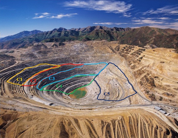
Example of slope sectorization. Aerial view of an open pit mine
Fig. 11 
The geotechnical sectorization for iron mine slopes with 10 m height and 7 m berm width
Fig. 12 
A Slopes with no appropriate geometry and B slopes with suitable geometry
Fig. 13 
A Erosions of the slopes due to over-flowing and B slopes with good drainage
Fig. 14 
A Slope with potential to planar failure and B slope with rockfalls
Fig. 15 
A Erosions in two subsequent benches and B no erosions on slopes
Fig. 16 
A Slope with more than one crack and B isolated cracks
Slopes with permanent deformation, in general, are associated with a deformation mechanism, while slopes with recurrent deformation can be associated with rainy seasons or even mining development.
-
-
7.
Visual field inspections: this information is obtained by visual inspections carried out by geotechnical or technicians. Therefore, the lack of inspection in the selected sector implies a depreciation of 4 points on the slope’s classification.


GAMAH-R index map
The map of mining rock slopes providing guidance, not only for repair and monitoring works, but also an assessment of performance of the slopes along the pit and is used to:
-
1.
Indicate the slopes more susceptible to good performance.
-
2.
Quantify the instrumentation of the open pit.
-
3.
Guide field inspections.
-
4.
Define regions where probabilistic stability analyses should be carried out.
-
5.
Support mining plans and the maintenance of slopes.
-
6.
Select slopes that must undergo a risk analysis.
This map is the clustering of slopes in accordance with the ranking. It should not be confused with risk maps, as these should include the damage.
The GAMAH-R map shows regions of the mine where the slopes do not behave according to the design premises, which would show the most critical sites for failures (preliminary failure susceptibility map), as it partially answers questions raised in this type of study, i.e. where they occur and what are the possible types of failure.
CASE studies: GAMAH-R index to three mines in east limb of Moeda syncline
The GAMAH-R classification system was applied to rock slopes of three iron mines, A, B and C, located on the eastern limb of the Moeda syncline (Fig. 8), and the charts of classifications for some of the compartments of each mine are shown on Figs. 17, 20 and 24.

Mine A, compartment C8. In purple, the selected parameters
These mines show different operational development: mine A is characterized a recently opened mine on the hillside with dry slopes. Mine B is a well-developed open-pit mine, with water inflow. Mine C is defined as an old open-pit mine with water drawdown by pump wells.
MINE A
Mine A was divided into 15 compartments, according to the dip direction of the slopes and main accesses. As an example, the compartment C8, localized on north of mine, was classified according to the chart GAMAH-R in Fig. 17. It is a compartment with NW direction and height of 70 m, between 1420 and 1490 m elevations, with an inter-ramp angle of 26° (Fig. 18A). The rock mass is formed by hard, medium and soft itabirites, with the discontinuities characterized by the compositional banding Sb and three families of fractures.

A Overview of the north slope of mine A. The compartment C8 is in intermediate portion of the slope. B Overflow of water (class 4) causes erosion on subsequent slopes (4). This slope belongs to the compartment C8
Because there are no inspections in this part of the slope, the score was penalized by 4 points, and the GAMAH-R index for this slope was 19, i.e. a T4 slope.
The susceptibility map of rock slopes of mine A (Fig. 19) shows that in this mine T4 slopes predominate, i.e. with GAMAH-R index between 16 and 20. This classification is mainly due to erosion processes occurring in the slopes (Fig. 18B).

Susceptibility map of mining rock slopes (GAMAH-R Map) of mine A. The legend of classes is red for slopes T5, orange for slopes T4, yellow for slopes T3, blue for slopes T2 and green for slopes T1
MINE B
Mine B, a well-developed open-pit mine, was divided into 4 compartments, according to the dip direction of the slopes and the bottom pit. As an example, compartment C2, localized on northeast of mine, was classified according to the chart GAMAH-R in Fig. 20. It is a compartment with NW direction and height of 211 m, between 1207- and 1418-m elevations, with an inter-ramp angle of 28° (Fig. 21A). The rock mass is formed by medium and soft itabirites and laterites, with the discontinuities characterized by the compositional banding Sb and three families of fractures (Fig. 21B).

Mine B, compartment C2. In purple, the selected parameters

A Overview of the northeast slope of mine B (compartment C2). B Medium itabirite with three planes of weakness, two vertical and one sub-horizontal
The compartment C2 shows erosion due to slope overflow (Fig. 22A) and circular failure on slope excavated in laterites (Fig. 22B).

A Slope overflow. B Circular failure on slope excavated in laterite
The susceptibility map of rock slopes of mine B (Fig. 23), a deep open pit, shows that the slopes belong to classes T5, T4, T3 and T2. The slope T5 of compartment C3 presents toppling and permanent deformation.

Susceptibility map of mining rock slopes (GAMAH-R Map) of mine B. The legend of classes is red for slopes T5, orange for slopes T4, yellow for slopes T3, blue for slopes T2 and green for slopes T1
MINE C
Mine C was divided into 6 compartments, according to the dip direction of the slopes and the bottom pit. As an example, compartment C3, localized on south of mine, was classified according to the chart GAMAH-R in Fig. 24. It is a compartment with NNE direction and height of 40 m, between 1380 and 1420 m elevations, with an inter-ramp angle of 25°. The rock mass is formed by quartz-sericite-phyllites and laterites, with the principal discontinuity characterized by the compositional banding Sb (Fig. 25A).

Mine C, compartment C3. In purple, the selected parameters

A Slope with adequate geometry, drainage berm and no erosions. B Slope’s cracks
Compartment C3 shows adequate geometry, drained berm, no erosion (Fig. 25A) and slope’s cracks (Fig. 25B).
The susceptibility map of slopes of mine C (Fig. 26) indicates a predominance of slopes of class T2, due to some final pit slopes with geometry according to geotechnical sectorization and maintenance drainage system.

Susceptibility map of mining rock slopes (GAMAH-R Map) of mine C. The legend of classes is red for slopes T5, orange for slopes T4, yellow for slopes T3, blue for slopes T2 and green for slopes T1
Failure susceptibility matrix for rock slope mining
Herein too, a proposal and a case study are still under development in the Ph.D. thesis of the first author, for the new mining slope failure susceptibility analysis procedure correlating the Global Slope Performance Index system (GSPI) and the slope classification system, GAMAH-R. This is present as a susceptibility matrix to mining rock slopes (MatRTRM) (Fig. 27), in which the less susceptible slopes will take the fields near the origin of the matrix.

The GSPI classification to compartment C8 from mine A
GAMAH-R does not indicate the instability or slope failure. For this reason, the relationship with the GSPI system is necessary, understanding that these systems complement each other. The correlation made it possible to select the most unstable slopes, which provide a risk management tool for mining slopes, so that the ones with medium–high to high susceptibility were selected for stability analysis, according to a probabilistic approach.
For high slopes (above 500 m) (Sjöberg 1999) due to the requirement of GSPI parameters, such as intact rock, geological structures and hydrogeological variations, the sectorization of the slopes must take into account the litho-structural domains.
Case study: failure susceptibility matrix for mine A
One of the applications of the GAMAH-R slope classification system is the determination of the failure susceptibility matrix of mine rock slopes.
Mine A was chosen as a case study for applying the failure susceptibility matrix by the correlation between the GSPI and GAMAH-R systems.
As example, the GAMAH-R index of the compartment C8 is showed in Fig. 17, and the GSPI is represented in Fig. 27.
Figure 28 shows the failure susceptibility matrix for all slopes of mine A, considering the correlation values obtained from GAMA-H and GSPI.

Failure susceptibility matrix for rock slopes mining, correlating the GAMAH-R and GSPI systems. The fields in red are of high susceptibility to failure, the fields in orange are medium–high, the fields in yellow medium–low and the fields in green are low susceptibility. C1 and C2 are the sectorization of the slopes from mine A. The fields defined by square are under study
A direct correlation between the GAMAH-R and GSPI system is expected, due to the same number of parameters (5), with the same weight for each element (1 to 5), and these systems are interchangeable and complementary. In this way, the matrix may show the null or non-applicable extreme fields, since they represent the inverse relationship between the systems. Among the studies are the extreme fields of the failure susceptibility matrix (squares with black outline in Fig. 27), as these probably did not present classified slopes.
Thus, it will be able to compare different mines, in their different stages in relation to the mining and pit geometry, as a function of the distribution of the slopes, represented by points in the failure susceptibility matrix.
Conclusions
Rock mass classification systems (Rock Mass Rating, Q System, Geological Strength Index, etc.) are used in slope designs to establish construction methods or parameters of strength and deformability of rock masses. In this way, they classify the rock masses and not the excavated slopes.
The GAMAH-R, a new mining rock slope classification system, allows the mining operation group (miners, geotechnics and technicians) to assign time action and responsibilities necessary to ensure better slope stability in iron ore mines. This system allows to group the slopes into five categories, T1, T2, T3, T4 and T5, according to the GAMAH-R index, defined by the sum of the scores given by five parameters: slope geometry, water seepage and berm drainage conditions, failure modes, erosion processes evaluation and history of past slope failures. The values of the groups vary from 5 to 25, where 5 denotes a slope with good performance (T1) and 25 a slope with low or poor performance (T5). For a good performance, a low GAMAH-R index (T2 and T1), the slope is expected to have a geometry in accordance with the geotechnical requirements, a good drainage system, no failure, no erosion and no deformation history. This is probably due to good design and maintenance, especially in relation to the drainage system. A poor performance, a high GAMAH-R index slope (T4 and T5), is directly associated with no adequate bench geometry, deteriorated rain drainage system and mainly with active failure and deformation mechanisms, most often perceived by tensile cracks, which can, if not treated properly, cause the rupture and even its collapse.
The classification provided the representation of the mining slopes in a map (GAMAH-R Map) that can be constantly updated, providing a reliable and useful tool to visualize the slopes most susceptible to instabilities, and is used to quantify the instrumentation of the open pit, guide field inspections, define regions where probabilistic stability analyses should be carried out, support mining plans and the maintenance of slopes and select slopes that must undergo a risk analysis.
GAMAH-R system was applied on three iron mines, A, B and C, located in the western Quadrilátero Ferrífero, Brazil. These mines show different operational development: mine A is characterized a recently opened mine on the hillside with dry slopes. Mine B is a well-developed open-pit mine, with water inflow. Mine C is defined as an old open-pit mine with water drawdown by pump wells.
The performance map of mine A, a hillside mine, shows that predominate T4 slopes, mainly due to erosive processes caused by inefficient drainage system. Mine B, a deep open pit, shows that the slopes belong to classes T5, T4, T3 and T2, due to the failure mechanisms. Mine C, due to some final pit slopes with geometry according to geotechnical sectorization and maintenance drainage system, indicates a predominance of slopes of class T2.
The authors believe that some parameters of the Mine Slope Instability Index—MSII (Naghadehi et al. 2013) have little relevance for the slope excavated selection on iron mines on tropical areas. Iron mine pits are, in general, opened on metamorphic rocks, with little lithologic variation, mainly composed by itabirites, quartzites, schists and phyllites. Tectonic regime has also uncertainties, as the highest score is related to thrust faults, and the lowest score is related to the absence of tectonic structures. This does not happen on very deformed pre-Cambrian regions, as there are several overlapped geological structures. As some of the slopes have been excavated a long time ago, detonation is also not of key importance. As the climate of tropical areas has rainfall much higher than 600 mm/year, the index proposed is not applicable for these zones.
The GSPI is essentially a slope rating system. However, it is fundamentally different from many of the systems used in general slope design practice. In part because of the complexity of design in many rock masses, many attempts have been made to correlate rock slope design with rock mass parameters or slope design angles, using simple classification systems. One of the benefits of the GSPI over these rating systems is that it requires the engineering geologists to directly evaluate the input parameters at the scale of the slope under consideration. The GSPI is also not related to slope angle and makes no attempt to predict this, because the GSPI is designed for use with excavated slopes, at least at this stage, and all of these excavated slopes have been the subject of a slope design (after Sullivan, 2013).
The proposal for a new methodological failure susceptibility analysis applied to the mining of rock slopes is still under study and under development in the Ph.D. thesis of the first author, based on correlations between GSPI and GAMAH-R.
The slopes C3, C4, C7, C9, C10, C11 and C13 should be assessed by more detailed stability analyses carried out from a probabilistic approach, which will determine the probability of failure, because they are situated in medium–high field (orange field) in the MatRTRM, i.e., with GAMAH-R greater than 15 and GSPI greater than 10. The slopes C1, C2, C5, C6, C8, C12, C14 and C15 are situated in the field medium–low susceptibility (yellow field) and can be evaluated by deterministic approach which is stable by GSPI system. Although slopes C6 and C8 are in the field of medium–high susceptibility, they are stable for the GSPI system.
Change history
23 July 2021
A Correction to this paper has been published: https://doi.org/10.1007/s10064-021-02374-4
References
Aleotti P, Chowdhury R (1999) Landslide hazard assessment: summary, review and new perspectives. Bull Eng Geol Env 58:21–44
Chemale F Jr, Rosière CA, Endo I (1994) The tectonic evolution of the Quadrilátero Ferrífero, Minas Gerais, Brazil. Precambrian Res 65:25–54
Corominas J, van Westen CJ, Frattini P, Cascini L, Malet JP, Fotopoulou S, Catani F, Van Den Eeckhaut M, Mavrouli O, Agliardi F, Pitilakis K, Winter MG, Pastor M, Ferlisi S, Tofani V, Hervás J, Smith JT (2014) Recommendations for the quantitative analysis of landslide risk. Bull Eng Geol Environ 73:209–263
Costa ISL, Silva GF, Ferreira MV (2019) Application of Zipf’s law to estimate undiscovered Gold endowment in the Quadrilátero Ferrífero Province, Brazil. Journal of the Geological Survey of Brazil 2(3):165–172
CPRM, CODEMIG (2014) Mapa Geológico do Estado de Minas Gerais. Escala 1:1.000.000. Belo Horizonte, CODEMIG, CPRM. Available online at: http://rigeo.cprm.gov.br/jspui/handle/doc/20786
Davis GH (1984) Structural geology of rocks and regions. John Wiley & Sons, New York
Diniz NC (2005) Caracterização Geomecânica de Maciços Rochosos. Dissertação. Faculdade de Tecnologia, Dept. Engenharia Civil & Ambiental Geotecnia, Universidade de Brasília. (In Portuguese)
Ferentinou M, Fakir M (2018) Integrating rock engineering systems device and artificial neural networks to predict stability conditions in an open pit. Eng Geol 246:293–309
Grenon M, Hadjigeorgiou J (2010) Integrated structural stability analysis for preliminary open pit design. Int J Rock Mech Min Sci 47(3):450–460
Hippertt J, Davis B (2000) Dome emplacement and formation of kilometre-scale synclines in a granite–greenstone terrain (Quadrilátero Ferrífero, southeastern Brazil). Precambr Res 102:99–121
ISRM (2007) The complete ISRM suggested methods for rock categorisation, testing and monitoring. In: R Ulusay, JA Hudson (Eds). International Society for Rock Mechanics Turkish national Group, Ankara, Turkey, p 1974-2006
Karam KS, He M, Sousa LR (2015) Slope stability risk management in open pit mines. In: Conference 7th Git4ndm Amd 5th Eogl International Conference. Project: Slope Stability in Rock Formations. UAE University, Al-Ain, p 19
Lee EM, Jones DKC (2004) Landslide risk assessment. Thomas Telford, London, p 454
Marinos P, Hoek E (2000) GSI: A geologically friendly tool for rock mass strength estimation, in Proceedings GeoEng 2000 Conference, 19–24 November 2000, Melbourne, Australia, Technomic Publishing Company, Lancaster, vol. 1, p 1422−1440
Menezes DA, Carneiro SRC, Meireles BP (2019) Map of the potential geotechnical susceptibility for operational pit slopes. REM, Int Eng J 72(1):55–61. https://doi.org/10.1590/0370-44672018720137
Naghadehi MZ, Jimenez R, Khalokakaie R, Jalali SME (2013) A new open-pit mine slope instability index defined using the improved rock engineering systems approach. Int J Rock Mech Min Sci 61:1–14
Pantelidis L (2011) A critical review of highway slope instability risk assessment systems. Bull Eng Geol Environ 70:395–400
Read JRL, Stacey PF (eds) (2009) Guidelines for open pit slope design. Csiro Publishing, p 496
Sjöberg J (1999) Analysis of large-scale rock slopes. Doctoral thesis. Lulea University of Technology, Division of Rock Mechanics
Sullivan TD (2013) Global Slope Performance Index. In: Slope Stability 2013. International Symposium on Slope Stability in Open Pit Mining and Civil Engineering Electronic. (Keynotes). Brisbane, Australia
Van Westen CJ, Seijmonsbergen AC, Mantovani F (1999) Comparing landslide hazard maps. Nat Hazards 20:137–158
Van Westen CJ, Van Asch TWJ, Soeters R (2006) Landslide hazard and risk zonation—why is it still so difficult? Bull Eng Geol Env 65:167–184
Varnes DJ (1984) Lanslide hazard zonation: a review of principles and practice. UNESCO, Paris, p 63
Wesseloo J, Read J (2009) Acceptance criteria. In: JRL Read, PF Stacey (Eds). Guidelines for Open Pit Slope Design. Csiro Publishing, p 221–236
Williams P, Floyd J, Chitombo G, Trevor Maton T (2009) Design implementation. In: JRL Read, PF Stacey (Eds). Guidelines for Open Pit Slope Design. Csiro Publishing, p 265–326
Acknowledgements
The authors thanks to the Núcleo de Geotecnia Aplicada (NUGEO), of the Escola de Minas (EM), of the Universidade Federal de Ouro Preto (UFOP) and the VALE S.A. for the support to the development of this research.
Author information
Authors and Affiliations
Corresponding author
Additional information
The original article contains an error in author name. “Ferreira” was listed twice during processing.
Rights and permissions
About this article

Cite this article
Ferreira Filho, F.A., Gomes, R.C. & da Costa, T.A.V. GAMAH-R: a new mining rock slope classification system. Bull Eng Geol Environ 80, 7287–7308 (2021). https://doi.org/10.1007/s10064-021-02330-2
Received:
Accepted:
Published:
Issue Date:
DOI: https://doi.org/10.1007/s10064-021-02330-2