
Abstract
Nonmetallic inclusions can affect resistance of steels to both general and localized corrosion, including pitting corrosion, stress corrosion cracking (SCC), and hydrogen-induced cracking (HIC). Because stress corrosion cracks frequently initiate at pits, and pits nucleate at sulfides, the presence of sulfides is likely to affect the SCC process. Nonmetallic inclusions increase susceptibility of steel to HIC, which occurs by the formation of internal hydrogen blisters or blister-like cracks at internal delaminations or at nonmetallic inclusions in low strength materials. HIC occurs when H atoms diffusing through a linepipe steel become trapped and form H2 molecules at inhomogeneities in the steel. A planar, gas-filled defect is created, which grows parallel to the pipe surface as it continues to trap more diffusing H atoms. If the defect grows sufficiently large, it may develop into a blister. HIC failure occurs if a mechanism exists for linkage of defects or blisters with the internal and external surfaces. The H atom source is normally the cathodic reaction of an acid corrosion mechanism occurring at the internal linepipe surface, i.e., the reduction of hydrogen ions, H+:\( \begin{gathered} {\text{Anodic reaction}}:{\text{ Fe }} \to {\text{ Fe}}^{{2 + }} + {\text{ 2e}}^{ - } \hfill \\ {\text{Cathodic reaction}}:{\text{ 2H}}^{ + } ~ + {\text{ 2e}}^{ - } ~ \to {\text{ 2H}}_{\text{ads}} \hfill \\ \end{gathered} \)
Introduction
Cracks in linepipe steel
There are many reasons for cracks to occur in a linepipe: cracks can develop from: (a) material defects; (b) during the plate to pipe rolling fabrication; (c) from hydrogen in the welds; and (4) in root beads or fill passes which are too thin or too weak. Defects in the linepipe can grow due to fatigue during the pipe operation. In-service crack growth mechanisms include, stress corrosion cracking (SCC) and hydrogen-induced cracking (HIC).
SCC is a form of environmentally assisted cracking (EAC) that is of great significance to the oil and gas pipeline industry. When ground water penetrates under the pipe coating, cracks may develop and grow through the external pipe wall. Over the last decades, thousands of colonies of such cracks have been found in pipelines. These cracks frequently become dormant at depths of about 1 mm. Occasionally, the cracks continue to propagate, leading to pipe rupture [1].
HIC occurs in a steel if there is a susceptible microstructure (metallurgical factor) and sufficient diffusing hydrogen (H) atoms to initiate and propagate damage (environmental exposure factor). These two factors are interrelated. All steels have a unique critical or threshold value of H atom concentration for initiation of hydrogen damage. If the concentration of diffusing H atoms (C HO value) is measured at the charging surface, this threshold value is expressed as (C HO )Th.
The effects of both metallurgical and environmental factors on SCC and HIC are discussed in this paper.
Stress corrosion cracking phenomena
SCC mechanism
SCC has been observed on the soil side of buried, natural gas pipelines since the early 1960s. Transgranular cracking occurs in environments with pH about 6.5, and is referred to as near-neutral pH stress corrosion cracking, as opposed to high-pH stress corrosion cracking, which is intergranular in nature.
SCC results from multiple metallurgical, mechanical, and environmental factors. Chemical composition of the steel, residual stress in the steel as well as applied stress, water chemistry in the field, including CO2, oxygen, and ionic concentrations in the groundwater near the pipe surface, may all have an effect on crack initiation and propagation [2–6]. Stress corrosion cracking in pipelines involves several steps: (a) the coating applied to the pipeline during installation becomes degraded, an electrolyte comes into contact with the surface, and the environment that causes SCC to develop; (b) the initiation and growth of multiple cracks that form colonies; (c) these cracks may continue to grow and coalesce; and (d) in the final step, a dominant crack reaches a critical size for rapid growth to failure, producing either a leak or a rupture, Fig. 1. The time to failure depends on a number of factors, including the pipe material, stress history, environment, and crack distribution. Nevertheless, most colonies do not result in failure as the cracks become dormant.

Small ‘SCC’ cracks that are widespread in tape-coated pipeline
Nearly all studies of SCC have been carried out without distinguishing the characteristics of initiation from those of propagation. Many of the studies on propagation have focused on growth of long cracks in pre-cracked specimens. Initiation of SCC is, however, studied using specimens that are not pre-cracked. The definition of an initiated crack is not well defined, and there is no clear mechanistic interpretation of the events that lead to initiation.
SCC has been observed to initiate from the base of localized corrosion sites (i.e. pits, crevices) for a variety of metal–environment combinations [7–10]. There remains debate on whether the stress intensification at the base of the pit or the enhanced electrochemical conditions within the pit are the controlling factor in SCC [11–14]. Several investigators believe it is the localized environment that plays the biggest role in crack initiation and not necessarily the stress concentration provided by the localized corrosion site [15, 16], whereas others believe that crack initiation in smooth samples requires the presence of a stress raiser [17]. The most common way to establish such a stress raiser is either through corrosion or mechanical damage.
Initiation of SCC
There are generally three stages of the cracking process: (a) generation of an environment that causes cracks to initiate; (b) initiation of cracks; and (c) propagation of cracks until failure occurs. The present study is focused on crack initiation, role of crack initiation sites, inclusions, factors governing crack growth, and the crack coalescence process in the context of low-pH SCC in linepipe steel.
For the current research, the validation of the results under accelerated test conditions is based on the assumption that the micro-processes, microstructural features, and specific sites associated with initiation of cracks in laboratory tests are those associated with the initiation of SCC in operating pipelines.
-
The results of laboratory tests show that cracks initiate at sites that are related to metallurgical factors, such as nonmetallic inclusions (Fig. 2). Nonmetallic inclusions and other forms of surface discontinuity or surface defects exert a significant influence on pits and microcrack initiation. Nonmetallic inclusions can serve as germs for the formation of pits and domains of intense etching of the surface of pipes.
Fig. 2 
EDS spectra indicating chemical composition of three different inclusions as associated with the initiation of pits in X-65 steel sample (before and after test at σ max = 90%YS, R = 0.6 and f = 0.1 Hz in NS-4 solution saturated with N2/5%CO2). Note the rapid dissolution of CaS inclusions and the formation of corrosion pits around the inclusions [7]
-
The time-dependence of crack development includes the following factors: (a) existence of an incubation period, (b) changes in crack number density, crack size with time, dormancy, and (c) the crack growth rate (Fig. 3). Many cracks are found to become dormant, and hence, are innocuous. Significantly, dormant cracks are always found near the site of ruptures (Fig. 4), so it is felt that these cracks are sometimes precursors to rupture [18]; and
Fig. 3 
a Development of pits from inclusions and b nucleation of cracks at pits in a sample of Steel X-65. The specimen was tested in NS4 solution saturated with CO2 at σmax = 70% YS, R = 0.6 and f = 0.1 Hz. In c EDS spectrum reveals the elements: Na, Mg, Al, Si, P, S, Cl, K, and Ca
Fig. 4 
a Failure in hydrostatic testing, SCC as root cause; b magnetic particle inspection (MPI) picture of SCC colony found next to a pressure failure. The outside pipe surface shows additional, longitudinal cracks adjacent to the fracture origin
-
The spatial distribution of cracks is also relevant. Spacing affects crack interaction and coalescence and significantly influences the overall cracking behavior, and hence, the lifetime of a pipeline. The linking or coalescence process for neighboring growing cracks (Fig. 5) was proposed [19, 20] as a means to encourage growth, and was shown by measurements to be more likely associated with crack tip dormancy [21–23].
Fig. 5 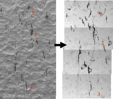
Development of cracks showing the interaction and coalescence of cracks. (Observations were made on replicas) [7]


There are several implications of the above factors on the operation of a pipeline. The source of stresses that are exerted on the pipe during its operation must be considered; e.g., the operating pressures in the pipeline and more importantly the pressure variation during operation. Other implications are concerned with the type of soil surrounding the pipe and ground movements, including frost heave and thaw settlement, which could apply external stresses to the pipe. The type of soil and how it could affect the acidity, or pH, of the groundwater around the pipe is also important. Metallurgical factors relate to nonmetallic inclusions in the steel from which the pipe is made and the steelmaking practices used in its production. Other metallurgical factors relate to the mill welds used to make the linepipe and the field welds that are used to join the pipes.
Complexities in SCC phenomena
SCC in steels for oil and gas pipelines is a very complex and challenging phenomenon. The complexity of SCC is reflected in the changes, with time, of the diverse parameters influencing the cracking phenomena, whereas the biggest challenge is in obtaining field-relevant reproducible laboratory data. SCC encompasses major effects from metallurgical, mechanical, and environmental parameters, all of which can be dominant under specific conditions. Adding to the complexity are the loading conditions in operating pipelines that define the mode of failure as SCC or, considering dynamic loading, possibly as corrosion fatigue (CF; Fig. 6).

Surface morphology of specimen (X-52), containing cracks that developed during pipeline operational service. The cracks numbered linked during testing in NS4 solution saturated with 5%CO2/N2, leading to failure
Hydrogen-induced cracking
HIC is one of several related mechanisms whereby absorbed hydrogen atoms can compromise the integrity of linepipe steels. The development of internal cracks in linepipe steels as a consequence of the trapping of absorbed hydrogen atoms (H atoms) as gas molecules (H2 molecules) at inhomogeneities is termed HIC. The cracks most often (but not always) lie parallel to the rolling plane and to the surfaces of the steel component. Residual or applied tensile stress is not needed for HIC development, Fig. 7. The HIC is typically associated with non-metallic inclusions such as elongated manganese sulfides (MnS), Fig. 7b.

Hydrogen induced cracking of carbon steel pipeline showing a HIC; b crack at MnS inclusion location and c near the pipe surface rough convex bumps called “blisters”
When hydrogen permeation causes the hydrogen concentration to exceed a critical value, hydrogen induced cracking results, as shown in Fig. 8a. It is well-known that the cracking in H2S environments is associated with the presence of non-metallic inclusions, especially MnS, and a banded structure [24]. The interfaces between large MnS inclusions and/or the banded structure and matrix usually act as sinks for hydrogen (Fig. 8b). Hydrogen tends to diffuse to these interfaces and reach the critical value. Since the cracks initiate at the elongated MnS particles, the HIC susceptibility decreases with decreasing sulfur content. Rolling at lower temperature increases HIC susceptibility by elongating the sulfide inclusions. The increased susceptibility could be due to the interface reaction between steel and the wet H2S environment.

a Hydrogen blister in NPS 6 sour gas pipeline (Canada 1997 Failure); b Blistering and through-wall crack in seamless linepipe (arrow shows leak location at blister; courtesy of M. Hay/Shell Canada)
Atomic hydrogen diffuses into the steel, forming blisters in the microscopic voids around nonmetallic inclusions. The gas pressure in these blisters generates very high localized stress, which initiates cracking along lines of weakness in the steel. Blisters often occur when the hydrogen-induced crack is unable to propagate further in the parallel-to-surface direction, and is unable to link up with HIC on adjacent planes in the steel (Fig. 8b). This may be because the hydrogen atom-trapping inhomogeneity which caused the blister to form has a finite length; Fig. 8a
A special form of HIC may occur when the local stress concentration is high in a sour service pipeline namely “stress-oriented hydrogen induced cracking (SOHIC)”. High stress fields can allow the hydrogen to accumulate without the need for inclusions or other interfaces. For example, some types of spiral-welded pipe exhibit highly stressed regions close to the seam weld, caused during the edge-forming process, Fig. 9. The presence of tensile stress in the component may cause individual ligaments of HIC to form in a stacked, through-thickness array. This is a necessary precursor to what is called SOHIC. This array is oriented perpendicular to the principal applied stress. The HIC may subsequently completely link up to cause through-wall cracking and loss of linepipe integrity, i.e., SOHIC. Like SWC, SOHIC is probably a combination of HIC and either hydrogen embrittlement cracking (HEC) or sulfide stress cracking (SSC) as shown in Fig. 10.

SOHIC failure of NPS 16 spiral-welded linepipe (Canada 1979 failure; courtesy M. Hay/Shell Canada)

StepWise cracking in plate steel exposed to sour gas (Lab. C-ring test)
In the study reviewed in this paper, we examined the role of nonmetallic inclusions in the initiation and propagation of cracks in a series of linepipe steels.
Role of inclusions in HIC
The EDX microanalysis revealed that the inclusions in cracks are manganese sulfide. The present investigation shows that MnS inclusions are the dominant initiation sites for cracking. In fact, microvoids around MnS and other inclusions provided sites for hydrogen to accumulate, leading to higher HIC susceptibility (Fig. 11).

Hydrogen-induced cracking. Blister crack
In order to quantify the relationship between HIC and non-metallic inclusions, specifically planar arrays of aligned inclusions, quantitative metallographic information was developed for the inclusion population in a number of linepipe steels that were assessed for HIC. Chemical compositions and yield strengths of these steels are listed in Table 1. This was achieved by image analysis where two types of inclusion geometry were identified and measured separately, namely, long strings of fragmented inclusions and other dispersed inclusions. The end map shown in Fig. 12 illustrates these two types. The map is basically a low magnification assembly of the metallographic information observed at high magnification, indicating the overall image of the inclusion population through the wall thickness of the linepipe steel. The sample is covered by 12 microscopic fields through the wall thickness (6 mm) and 46 fields in the longitudinal direction (each field is 400 × 400 μm). The end map shown in Fig. 12 identifies susceptible areas for hydrogen induced cracking on the sample as indicated by the thick solid lines (representing long strings of fragmented inclusions) and the blister crack in Fig. 11.

The image analysis methodology where maps are constructed and used to measure long microscopic features that run through more than one microscopic field. Measurements of non-metallic inclusions in line pipe steels
Data on length of inclusions were investigated by image analysis (Fig. 12) and are reported in Table 2. The results are correlated with threshold hydrogen concentration, (C HO )Th, and plotted in Figs. 13 and 14. Both volume fraction and total length per unit area have a relationship with the threshold hydrogen concentration. It is clear from these figures that the steel with minimum inclusions has the highest threshold hydrogen concentration.

Effect of the volume fraction of inclusions (%) on threshold hydrogen concentration for cracking (C th)

Effect of the total length inclusions on threshold hydrogen concentration for cracking (C th)
The size and shape of the inclusions were considered to depend on the Ca/S ratio in steel. The Ca/S ratio [24, 25] in Table 2 showed that increasing the ratio of Ca/S decreases the hydrogen damage susceptibility (i.e., steels CTR-2 and AM-2). According to the results, steel susceptibility to SSC and HIC depends on the stress localization around large and hard inclusion particles. This localized stress could exceed the yield strength.
The metallurgical aspects of HIC can be summarized as follows: (a) the formation of internal blister cracks by the accumulation of hydrogen at inclusion microvoids, (b) the extension of these cracks parallel to the rolling plane by the internal hydrogen pressure, and (c) the linking of nearby cracks along directions inclined to the rolling plane by plastic deformation and fracture. The formation of blister cracks seems to be directly related to the type and distribution of nonmetallic inclusions in the steel. Extension of blister cracks takes place along paths of low-fracture resistance parallel to the rolling plane. The exact nature of these fracture paths is not known, but it has been suggested that the fracture paths are bands of certain transformation products in the steel. The linking of nearby cracks takes place along bands of localized shear, which result from the internal hydrogen pressure acting on elongated blister cracks.
Hydrogen, as an embrittling element in steels, is still a significant problem. The mechanism of hydrogen embrittlement in steels is not completely understood, especially since no one theory in particular is able to describe all of the hydrogen–metal interaction phenomena observed. From the various damage theories proposed, in the de-cohesion theory both the adsorbed and absorbed hydrogen may be accepted. According to the reduced atomic cohesion/model for hydrogen embrittlement proposed by Oriani [26], hydrogen embrittlement might be interpreted as being due to reduced atomic cohesion at the location of stress concentration by the accumulation of hydrogen atoms. The higher the C HO value, the greater the reduction in atomic cohesion at the stress concentration location.
Avoidance of HIC in new linepipe
Two measures can be taken to increase the HIC resistance of new linepipe: (1) lower C HO , the surface concentration of diffusing H atoms, and (2) raise (C HO )Th, the threshold surface concentration of diffusing H atoms to initiate HIC.
Lowering the C HO value
The C HO value can be lowered by such measures as chemical corrosion inhibition and encouraging the development of passivating iron sulfide films. Generally, we should not rely on coatings or corrosion inhibitors to protect steel (or other materials) from environmental embrittlement mechanisms such as HIC, SSC, and SOHIC. Materials should be selected that are inherently resistant to all known cracking phenomena. The C HO value may be reduced in some sour environments by alloying the steel with certain elements; e.g., Cu. Addition of Cu does not affect the (C HO )Th value. It merely prevents HIC in susceptible materials by keeping C HO < (C HO )Th in sour environments with pH values in excess of about 4.5. The presence of Cu is believed to stabilize the iron sulfide scale formed on the steel.
Raising the (C HO )Th value
The (C HO )Th value will be increased by: (a) eliminating type II MnS inclusions, Al2O3 particles, the anomalous micro-structure, and other nonmetallic inclusions, e.g., silicates, slag, iron oxides, massive niobium carbonitride particles, etc; (b) reducing the segregation of trace/impurity elements in the steel; and (c) increasing the homogeneity of the microstructure. The addition of calcium to form spherical, non-deformable calcium sulfide (CaS) inclusions is now the favored method of shape-controlling steels for HIC-resistant plate and linepipe. The Ca/S ratio must be controlled within a narrower range if the S content is higher than 0.003%. For a 0.004% S content steel, the maximum Ca/S ratio should be 2.5, whereas it should be 2.0 for a steel with 0.005% S. Shape control is not recommended if the sulfur content exceeds 0.005%.
Conclusions
SCC
-
1.
Multiple types of crack initiation sites exist for stress corrosion cracking of pipeline steel in low-pH solutions.
-
2.
Stress corrosion crack initiation is a competitive process; cracks initiate at the most favorable sites first, then at other sites.
-
3.
The correlation between pits and non-metallic inclusions indicates that pitting results from effects associated with inclusion composition.
-
4.
Some steels show a greater susceptibility than others. On occasion, this difference in material susceptibility has been the main factor in determining whether near-neutral-pH SCC is an operational problem.
-
5.
The harmful influence of hydrogen on steel depends on the character of hydrogen interaction not only with the crystal lattice of iron, but also with structural components and nonmetallic inclusions, in particular, manganese sulfides (MnS).
HIC
-
6.
There is a good correlation between inclusion measurements and HIC.
-
7.
HIC depends on both material composition and hydrogen concentration C HO . The HIC susceptibility would increase due to increased C HO as the consequence of decreased diffusion coefficient, D.
-
8.
The elongated MnS and planar arrays of other inclusions are primarily responsible for HIC.
-
9.
Lower volume fractions of inclusions correspond to higher resistance to HIC.
-
10.
The microstructure may also play a role in HIC, in particular, heavily banded microstructures could enhance HIC by providing low fracture resistance paths for cracks to propagate more easily. The balance of C and Mn has an overriding effect on resistance to HIC.
References
National Energy Board, Calgary, Alberta, Stress Corrosion Cracking on Canadian Oil and Gas Pipelines, Report No. MH-2-95, 1996
Sutcliffe JM, Fessler RR, Boyd WK, Parkins RN (1972) Stress corrosion cracking of carbon steel in carbonate solutions. Corrosion 28:313
Beavers JA, Harle BA (1996) Mechanisms of high-pH and near-neutral-pH SCC of underground pipelines. ASME International Pipeline Conference, Calgary, Alberta, June
Charles EA, Parkins RN (1995) Generation of stress corrosion cracking environments at pipeline surfaces. Corrosion 51:518
Parkins RN, Blanchard WK, Delanty BS (1994) Transgranular stress corrosion cracking of high-pressure pipelines in contact with solutions of near-neutral-pH. Corrosion 50:394
Delanty BS, Beirne JO (1992) Major field study compares pipeline SCC with coatings. Oil Gas J 90:39
Wang Y-Z, Revie RW, Shehata MT, Parkins RN (1998) Early stages of stress corrosion crack development of X-65 pipeline steel in near-neutral pH solution, materials for resource recovery and transport. Metallurgical Society of CIM 1998, 71
Beavers JA, Johnson JT (1998) Annual Report on Effects of Pressure Fluctuations on SCC Propagation”, Prepared for Line Pipe Research Supervisory Committee of PRC International, CC Technologies, Dublin, Ohio, May 1999
Parkins RN (1988) Mater Sci Eng A 103:143
Christman TK (1990) Corrosion 46:450
Silcock JM (1982) Corrosion 38:144
Brown BF, Beachem CD (1965) Corros Sci 5:745
Yasuda M, Weinberg F, Tromans D (1990) J Electrochem Soc 137:12
Issacs HS, Newman RC (1987) Local electrochemistry of pitting corrosion in stainless steels. Corrosion chemistry within pits, crevices, and cracks. HMSO, London
Dolphin AS, Turnbull A (1987) Experimental determination of the electrochemistry in corrosion-fatigue cracks in structural steel in marine environments. Corrosion chemistry within pits, crevices, and cracks. HMSO, London
Jonas O (1997) Molecular modeling of corrosive environments in cracks. Effects of the environment on the initiation of crack growth: ASTM STP 1298. ASTM, Philadelphia
Parkins RN (1984) Metals Technol 9:122
Parkins RN (1985) Mater Sci Technol 1:480
Elboujdaini M, Wang Y-Z, Revie RW, Shehata M, de Silveira G, Parkins RN (2001) Initiation of stress corrosion cracking in pipeline steel. GRI report no. GRI 05-0005
Elboujdaini M, Li J, Gertsman V, Gu G, Revie W, Gao M, Katz DC (2004) Stress corrosion cracking: microstructural and material properties for crack initiation of 16” X-52 line pipe steel. Corrosion 2004, Paper 04553, NACE, Houston, TX
Parkins RN, Delanty BS (1996) The initiation and early stages of growth of stress corrosion cracks in pipeline steels exposed to a dilute, near neutral pH Solution. Ninth Symposium on Pipeline Research, AGA Catalog No. L 51746, pp. 19-1 to 9-14
Elboujdaini M, Wang Y-Z, Revie RW, Parkins RN, Shehata MT (2000) Stress corrosion crack initiation processes: pitting and microcrack coalescence. Corrosion 2000, Paper 00379, NACE, Houston, TX
Chen W, King F, Vokes E (2002) Characteristics of near-neutral pH stress corrosion cracks in an X-65 pipeline. Corrosion 58:267
Elboujdaini M, Shehata MT, Revie RW (1998) Performance of pipeline steels in sour service. Proc. 37th Int Symp Materials for Resource Recovery and Transport, Conf of Metallurgists, CIM, Calgary, August
Standard Test Method TM-0284 - Test Method Evaluation of Pipeline Steels for Resistance to Stepwise Cracking - NACE International, Houston, TX, 1996
Oriani RA, Josephic PH (1980) Met Trans A 11:1809
Acknowledgment
The authors acknowledge helpful discussions with colleagues at the CANMET Materials Technology Laboratory.
Author information
Authors and Affiliations
Corresponding author
Additional information
Dedicated to the 85th birthday of John OM. Bockris.
Rights and permissions
About this article
Cite this article
Elboujdaini, M., Revie, R.W. Metallurgical factors in stress corrosion cracking (SCC) and hydrogen-induced cracking (HIC). J Solid State Electrochem 13, 1091–1099 (2009). https://doi.org/10.1007/s10008-009-0799-0
Received:
Revised:
Accepted:
Published:
Issue Date:
DOI: https://doi.org/10.1007/s10008-009-0799-0