
Abstract
Prosthetic component malposition is not infrequent, because of technical flaws, especially without a computed navigation system. We assumed that an inclined interline of a prosthetic knee with components parallel in the coronal plane provides a better load distribution and lower contact pressure towards a varus malalignment. For that we studied, using finite element analysis, load intensity and distribution for three situations: ideal alignment of prosthetic components, tibial varus malposition of 3° and 8° leading to tibio-femoral varus malalignment (i.e. an unbalanced knee) and the same tibial varus malpositions, but with the femoral component also malpositioned in the coronal plane, so that they are parallel, and with equally tightened collateral ligaments (i.e. a balanced knee). We found that maximum contact pressure and underlying bone compression forces are higher for a balanced knee with an inclined interline than in ideal alignment, but lower than in an unbalanced knee. According to our results, 2- and 4-mm additional medial plateau resection on a proper balanced knee does not significantly affect the load distribution towards ideal alignment. Balancing is a key factor for prosthetic survival in cases when a certain degree of coronal malposition cannot be avoided.
Introduction
Failure in total knee arthroplasty (TKA) remains multifactorial. Alignment plays an important role in loading of the underlying bone and has been associated with osseous failure and implant loosening in long-term studies on large cohorts of total knee arthroplasties [1]. Stresses may exceed the strength and durability of polyethylene, as has been shown by retrieval studies which have identified rapid wear of tibial components with pitting and delamination [2]. There are several theories regarding bone cuts during knee arthroplasty, and also some disagreement as to proper alignment. The established bone cut for the tibial component is perpendicular to the long axis of the tibia. According to Blaha et al. [3, 4], all bone resections should be parallel to the flexion axis of the knee. Prosthetic component malposition is not infrequent, because of technical flaws, especially without a computed navigation system. Sometimes, we deliberately remove additional tibial bone from the medial or lateral sides to balance the knee, so that the tibial component will no longer be perpendicular to the long axis of the tibia. According to other literature studies, under static loading, a tibial malposition of 3° or more in varus can greatly alter the distribution of pressure and the load between the medial and lateral compartments [5–7]. Despite this, we observed some cases of arthroplasties with varus malposition and long-term survival (more than 15 years—Fig. 1). Certainly not all knees with coronal malposition fail. We found no literature reports of a balanced knee associated with coronal malposition of prosthetic components. The purpose of this study was to determine using finite element analysis:

Varus tibial malposition—15 years after implantation Rx
-
how variations in tibial and femoral component angulation might affect the distribution of joint pressure;
-
whether there is decreased load pressure towards tibio-femoral malalignment, when these components are parallel in the coronal plane, in the case of a properly balanced knee, even if there is some degree of malposition.
Materials and methods
Computational simulations using finite element analysis focused on resistance augmentation, the influence of the prothesis upon the adjacent bone area and a comparison between load intensity and distribution for three situations:
-
a.
ideal alignment of prosthetic components;
-
b.
tibial varus malposition of 3° and 8° leading to tibio-femoral varus malalignment (i.e. an unbalanced knee);
-
c.
the same tibial varus malpositions, but with the femoral component also malpositioned in the coronal plane, so that they are parallel, and with equally tightened collateral ligaments (i.e. a balanced knee).
Varus malposition of the tibial component was defined as being equivalent to the clinical case when more bone might be removed medially and less might be removed laterally. The experiments for determining the in vivo kinematics of the joint were performed using SIMI Motion, the system for image acquisition and analysis (SIMI Reality Motion Systems GmbH). For the image acquisition phase, two high-speed Panasonic video cameras were used, in two perpendicular planes. In the last phase of image processing using SIMI software, the markers on every frame were automatically identified and the kinematic curves were drawn. The measurements were established for a patient weight of 75 kg. Centres of gravity were established in the mid-pelvic region, more precisely, in the middle of anatomical segments. In the present case, the acquisition of values was done for the maximal bearing moment, defined as the moment when the whole body mass leans on a single foot in walking. The entire calculation was made using an original Matlab computational program. Joint three-dimensional geometric reconstruction was achieved by patients’ CT serial sections and radiographic analysis before surgery. The computational geometric model of the joint was used for finite element analysis adding material characteristics kinetic and kinematic. Previously obtained three-dimensional models were imported into ANSYS software and meshed with finite elements. Because the femoral implant is made of CoCr, it is considered rigid; therefore, the elements from its mesh are considered coupled to the mass centre. An important reduction in the global numeric model is achieved, the freedom ranges of rigid element nodes being replaced by 6 freedom ranges of mass centre. The polyethylene erosion phenomenon may be quantified by introducing the results obtained for a movement cycle in mathematic formulas that calculate the quantity of material removed by friction, depending on contact pressure. The results are calculated for a position of 15° of flexion in walking, for which the axial efforts are the highest, according to calculation. The elastic modulus of the polyethylene was considered 1,016 MPa, and the Poisson constant, 0.46. The minimum thickness of the polyethylene insert was 9 mm.
Results
-
A.
For the ideal situation of proper alignment for prosthetic components, a maximum contact pressure of 11 MPa upon the polyethylene surface was observed, with symmetrical load distribution between the two compartments. The underlying bone compression forces have an average of 1.20 MPa, focusing on the interface with the implant.
-
B.
For a varus malposition of 3°, the maximum contact pressure upon the polyethylene component was 16.1 MPa, with a clear delimitation of the contact patch in the medial condyle area (Fig. 2). A slight anterior displacement of the contact patch to the medial area could be observed. The underlying bone compression forces had an average of 2.50 MPa, focusing on the internal cortical metaphysis (Fig. 3). For a varus malposition of 8°, the maximum contact pressure was 32.31 MPa upon the polyethylene component, with less obvious delimitation of the contact patch in the medial condyle area (Fig. 4). On the external condyle, the loading forces were distributed over a narrower area and closer to the insert centre. The underlying bone compression forces had an average of 6.20 MPa, with an almost symmetrical distribution from the medial epiphysis to the internal cortical metaphysis. On the external condyle surface area, pressure values were almost zero (Fig. 5).
Fig. 2 
Stress distribution and intensity upon polyethylene component for 3° of varus, balanced and unbalanced
Fig. 3 
Bone stress distribution and intensity for 3° of varus, balanced and unbalanced
Fig. 4 
Stress distribution and intensity upon polyethylene component for 8° of varus, balanced and unbalanced
Fig. 5 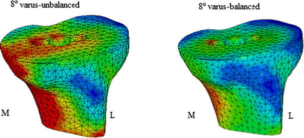
Bone stress distribution and intensity for 8° of varus, balanced and unbalanced
-
C.
The following results are for analyses with malposition of both components, which are nevertheless parallel in the coronal plane, resulting in proper knee balance. For a 3° varus malposition, the maximum contact pressure upon the polyethylene component was 12 MPa, with a clear delimitation of the contact patch in both condyle areas (Fig. 2). The underlying bone compression forces had an average of 1.90 MPa, focusing on the interface with the implant (Fig. 3). For an 8° varus malposition, the maximum contact pressure upon the polyethylene contact was 18.31 MPa, with less obvious delimitation of the contact patch in both condyle areas (Fig. 4). The underlying bone compression forces had an average of 3.20 MPa on the internal cortical metaphysis, and 2.50 on the external cortical metaphysis (Fig. 5).


Discussion
Consequently, primary goals of total knee replacement (TKR) are to correct frontal plane bony deformity, alleviate pain and restore function. The procedure typically corrects deformity via tibio-femoral realignment and ameliorates pain via joint resurfacing. The alignment is critical to load transfer at not only the articular surface but at the implant–host interface. Recreating, as closely as possible, the size and shape of the distal femur are equally important. The size, shape and position of the femoral component are intimately related to the balance and function of the ligaments. Tibial component sizing and orientation also affect the mechanics and longevity of the implant. Valgus or varus malpositioning of the tibial component of a total knee implant may cause increased propensity for loosening or implant wear and eventually may lead to revision surgery [5]. Most of the early failures of total knee replacements are related to technical flaws. Experimental and clinical data indicate that to achieve optimal midterm and long-term results of a TKR, good alignment in the frontal plane of the lower limb is mandatory. What “proper alignment” means is not unanimously agreed upon by researchers. According to Blaha et al. [3], all bone resections should be parallel to the flexion axis of the knee and the femoral coronal cut should be at 3° valgus. In an experimental study, Hsu et al. 14 showed that a femoral component in 7° valgus, with the tibial component placed at 90° to the long axis of the tibia, was the best position for the total condylar knee and produced equal force distribution between the medial and lateral plateaus [8]. For the kinematic knee, the best position was 9° valgus for the femoral component with 2° varus of the tibial component. A clinical association between failure of TKR and malalignment seems likely. Ritter et al. [9] 32 reported that varus knees had a lower survival at 10 years than aligned or valgus knees. Alignment in a narrow range around the neutral axis is a major objective of TKR even if the exact range is not clearly identified. To achieve this goal, different systems are available based on intramedullary or extramedullary rods that allow targeting. From experimental data and clinical studies, it has been shown that these systems have to be improved [10–13]. A series that evaluated 673 knees showed that only 75.3 % of the knees were in the 4°–10° valgus range [14]. Failures of total knee replacements are related to technical flaws. Understanding the variables that determine the accuracy of intramedullary alignment instruments is important. Their accuracy depends upon the intramedullary rod engaging the isthmus of the medullary canal to re-establish the anatomic axis. The rod length and diameter and the intramedullary diameter of the canal influence the precision of placement. Another important variable is the location of the entry hole for the intramedullary guides. The starting point for the placement of the intramedullary rod should be determined preoperatively because errors in placement can result in malposition of the femoral component. A starting point that is too lateral will increase valgus angulation, whereas a medial entry point will decrease valgus alignment. In a large femoral canal, excessive overdrilling of the entry hole can allow toggling of the guide rod that will also introduce variability in distal femoral alignment. The goal of tibial alignment in TKA is to orient the component at 90° to the longitudinal axis of the tibia in the coronal plane and, depending on the implant design, neutral to slight flexion (3°–7°) in the sagittal plane. Errors determined by rod entry point and toggling are still possible like those described for femur. For severe varus/valgus knees, significant long-standing deformity lead to medial/lateral structures fibrosis, so that is why some surgeons perform a tibial additional resection from medial/lateral side, leading to deliberate tibial malposition, in order to obtain adequate balancing. Although computer-assisted surgery has the potential for increasing the accuracy of alignment and sizing, it is still dependent on the surgeon entering the data (landmarks) at the time of surgery. If errors are made with localization of landmarks or topographic mapping, the alignment and sizing information provided by the computer will be inaccurate. All the above factors make prosthetic component malposition a not so uncommon situation. Conventional ancillary devices achieve good, but not ideal, alignment in the frontal plane in only an average of 75 % of total knee replacements. Through finite element models, stress distributions in tibial bearing components were simulated for different conditions of alignment. Knowledge of contact pressures and areas in total knee replacements are considered a reliable tool to predict the potential wear of UHMWPE demonstrated that more severe damage in total knee tibial components was associated with the higher contact stress on the tibial bearing component [15–20]. The evaluation of contact areas and pressures in total knee replacement is a key issue to prevent early failure. Bargren et al. [21] showed that when the knee is loaded unequally, liftoff occurs on the unloaded side and collapse occurs on the eccentrically loaded side. Several studies have biomechanically examined changes in wear or contact stress with increases in valgus or varus angulation of a tibial component. D’Lima et al. [7] using a knee wear simulator demonstrated a nearly three times increase in wear generated in implants mounted with a 3° varus malalignment. Matsuda et al. [6] determined that a 5° varus or valgus tilt increased the contact stresses by approximately 50 % in five different knee implants. In these two studies, varus or valgus malalignment caused liftoff of one condyle from the tibial component. All of these results are related to an unbalanced knee.
Our study revealed two situations of tibial malposition, one for an unbalanced knee and one for a balanced knee (femoral and tibial components are parallel in the coronal plane and collateral ligaments are equally tightened). Both situations are compared with the ideal case of proper alignment.
For the former case (unbalanced knee), we observed that the contact pressure upon the medial polyethylene increased by 5.1 MPa (46 %) and underlying bone compression forces were twice higher, focusing on the internal cortical metaphysis, even for 3° of varus malposition. When increasing varus malposition to 8°, the contact pressure upon the medial polyethylene was 3 times higher than in the ideal alignment, and the underlying bone compression forces had an almost symmetrical distribution from the medial epiphysis to the internal cortical metaphysis, which meant that the tibial prosthetic stem could not redistribute the forces anymore. Pressure values were almost zero on the external condyle surface area, and the knee could be unequally loaded, leading to liftoff.
For the latter case (balanced knee—femoral and tibial components are parallel in the coronal plane and collateral ligaments are equally tightened), we observed, for 3° of varus, a slight increase of 1 MPa (9 %) of the maximum contact pressure upon the polyethylene area. The clear delimitation of the contact patch on both condyles and underlying bone compression forces focusing on the interface with the implant were similar to those in the ideal alignment. Although we noticed a symmetrical distribution, the forces were greater. At 8° of varus, the pressure upon the polyethylene area increased by 7.3 MPa (66.3 %). The underlying bone compression forces influenced both the internal and the external cortical metaphyses, which means a decreased probability for liftoff towards 8° of unbalanced varus (Table 1). Nevertheless, the higher values of forces for this malposition could lead to polyethylene wear and collapse.
Conclusion
This study reveals the importance of balancing in TKA. Balancing is a key factor for prosthetic survival in cases when a certain degree of coronal malposition cannot be avoided. For an unbalanced prosthetic knee, greater pressure upon the medial compartment could lead to polyethylene wear even for 3° of varus malalignment and it could also increase the degree of malposition. 8° of varus malalignment could collapse the medial tibial bone and cause liftoff to the poorly loaded lateral condyle. For a balanced knee, we observed symmetrical distribution and lower values of contact pressure upon the polyethylene than in the first situation. However, polyethylene wear and medial bone collapse are still possible, especially at 8° of varus malposition. The results show that an inclined interline of a prosthetic knee with components parallel in the coronal plane is not as good as the ideal alignment but is certainly better than a varus malalignment. Achievement of an ideal alignment should be the goal in TKA, and when this is not possible due to various factors, a properly balanced knee could increase prosthetic survival. According to our study, a slight tibial cut leading to a varus tilt that does not exceed more than 3° could be an option for obtaining a balanced knee. Technical flaws, even with computer-assisted surgery, and additional tibial resection in severe varus/valgus knees, lead to prosthetic components coronal malposition, which is not an exceptional situation. Certainly not all knees with coronal malposition fail.
References
Berend ME (2010) Consequences of malalignment in total knee arthroplasty: few if any-opposes. Semin Arthroplast 21:99–101
Landy MM, Walker PS (1988) Wear of ultra-high molecular-weight polyethylene components of 90 retrieved knee prostheses. J Arthroplasty 3:73–85
Blaha JD, Mancinelli C, Simons W (2003) Kinematics of the human knee using an open chain cadaver model. Clin Orthop 410:25
Blaha JD, Mancinelli C, Simons W (2002) Use the trans epicondylar axis to define the sagittal morphology of the distal part of the femur. J Bone Surg Am 84:48
Werner F, Ayers D, Maletsky L (2005) The effect of valgus/varus malalignment on load distribution in total knee replacements. J Biomech 38:349–355
Matsuda S, Whiteside L, White S (1999) The effect of varus tilt on contact stress in total knee arthroplasty. Orthopaedics 22:303–307
D’Lima D, Hermida C, Chen P, Colwell C (2001) Polyethylene wear and variations in knee kinematics. Clin Orthop 392:124–130
Hsu RW, Himeno S, Coventry MB (1990) Normal axial alignment of the lower extremity and load-bearing distribution at the knee. Clin Orthop 255:215–227
Ritter M, Davis K, Meding B (2011) The effect of alignment and BMI on failure of total knee replacement. J Bone Jt Surg Am 93:1588–1596
Jiang CC, Insall JN (1989) Effect of rotation on the axial alignment of the femur. Pitfalls in the use of femoral intramedullary guides in total knee arthroplasty. Clin Orthop 248:50–56
Novotny J, Gonzalez MH, Amirouche FM (2001) Geometric analysis of potential error in using femoral intramedullary guides in total knee arthroplasty. J Arthroplasty 16:641–647
Reed S, Gollish J (1997) The accuracy of femoral intramedullary guides in total knee arthroplasty. J Arthroplasty 12:677–682
Cates HE, Ritter MA, Keating EM (1993) Intramedullary versus extramedullary femoral alignment systems in total knee replacement. Clin Orthop 286:32–39
Mahaluxmivala J, Bankes MJ, Nicolai P, Adlam CH, Allen PW (2001) The effect of surgeon experience on component positioning in 673 press fit condylar posterior cruciate-sacrificing total knee arthroplasties. J Arthroplasty 16:635–640
Bartel D, Bicknell V, Weight M (1986) The effect of conformity, thickness, and material on stresses in ultra-high molecular weight components for total joint replacement. J Bone Surg Am 68:1041–1051
Beillas P, Papaioannou G, Tashman S (2004) A new method to investigate in vivo knee behavior using a finite element model of the lower limb. J Biomech 37:1019–1030
El-Deen M, Garcia M, Jin M (2006) Effect of ultrahigh molecular weight polyethylene thickness on contact mechanics in total knee replacement. J Eng Med 220:733–742
Fregly B, Sawyer G, Harman K (2005) Computational wear prediction of a total knee replacement from in vivo kinematics. J Biomech 38:305–314
Halloran P, Petrella J, Rullkoetter J (2005) Explicit finite element modeling of total knee replacement mechanics. J Biomech 38:323–331
Gruionu L, Rinderu P (2005) A computational study of the tibial component biomechanical behaviour in TKA. In: 2005 Annual fall meeting, Baltimore. BMES, USA
Bargren JH, Blaha JD, Freeman MA (1983) Alignment in total knee arthroplasty. Correlated biomechanical and clinical observations. Clin Orthop 173:178–183
Conflict of interest
None.
Author information
Authors and Affiliations
Corresponding author
Rights and permissions
About this article
Cite this article
Stan, G., Orban, H., Gruionu, L. et al. Coronal malposition effects in total knee arthroplasty: a finite element analysis. Eur J Orthop Surg Traumatol 23, 685–690 (2013). https://doi.org/10.1007/s00590-012-1051-7
Received:
Accepted:
Published:
Issue Date:
DOI: https://doi.org/10.1007/s00590-012-1051-7