
Abstract
Because of the advantages of the high accuracy and reliability, the spatial pose measurement technology based on the cooperative target has been widely applied in the various fields such as aerospace, industrial intelligent manufacturing and medical intelligent diagnosis and treatment. As the key reference for the measurement, the cooperative target is an important part of the spatial pose measurement system, which design is one of the important factors affecting the measurement accuracy. In this paper, the technology status of the cooperative target for the spatial pose measurement is presented, focusing on the analysis and review of the structure design and the characteristics of the common components such as coating, cone corner prism and glass beads, etc. For more clearly description, many typical applications of the cooperative target for spatial pose measure are listed in this paper, and the prospect of the field is described.
Access provided by Autonomous University of Puebla. Download conference paper PDF
Keywords
1 Introduction
With the development of photoelectric detection and information processing technology, spatial pose measurement technology is widely used in various fields such as aerospace, industrial intelligent manufacturing, medical intelligent diagnosis and treatment. The cooperative target-based spatial pose measurement technology has the advantages of high accuracy, high reliability and high timeliness, and can be applied to space rendezvous and docking, workpiece grasping, large equipment pose measurement and other complex scenarios [1].
How to design the cooperative target is the primary problem to be solved in the study of spatial pose measurement system. The general cooperative target is a pattern marker of known size, shape and structure [2]. The cooperative target is the key reference for spatial pose measurement, and its selection is determined by the measurement conditions, installation environment and other factors, while its characteristics determine the spatial pose measurement algorithm design [3]. The reasonable selection and design of the cooperative target is one of the important factors affecting the accuracy index of spatial pose measurement.
2 Key Technologies of Cooperative Target
2.1 Design Principles
The design of the shape and pattern of the cooperative target should contain the exact information that can resolve the measured object’s positional parameters, meet the requirements of high measurement accuracy in complex operating environments. To ensure the robustness of the measurement system, the design should have enough information and the ability to resist light changes, pollution and occlusion interference [4]. The design of cooperative targets should accord with the following design principles:
-
(1)
The cooperative target should contain enough feature information to ensure that the detection system can acquire the information required for spatial pose measurement.
-
(2)
The feature pattern and color of the cooperative target should be significantly different from the surrounding environment in order to facilitate the detection system to identify the target.
-
(3)
The cooperative target should be simple and easy to follow for visual recognition processing in order to achieve the goal of real-time.
-
(4)
The structure of the cooperative target should be easy to install on the platform of the object to be measured, with good stability and redundant design of information that is resistant to pollution and obscuring.
-
(5)
It should be easy to produce and the mechanical accuracy can meet the engineering requirements [5].
2.2 Design Methods
As shown in Fig. 1, The design of the cooperative target includes the design of shape, size, color and material.

The Design contents of cooperative target
Firstly, according to the principle that the cooperative target should be simple and have enough feature information, the type of feature information of the cooperative target, such as point features, line features or curve features, is determined in combination with the application, the positional measurement algorithm, and the directivity. Cooperative targets are usually designed using shapes such as “H-shaped”, “T-shaped”, “circular” and “square”. The shape is related to the type, number and distribution of features. Secondly, the size of the cooperative target is designed according to the mutual constraints of the camera parameters and the cooperative target, including the location and size of the features. Then the color and material of the cooperative target are designed according to the application environment. Finally, the validation for the rationality of the cooperative target design is carried out through simulation and experimentation.
The measurement accuracy is directly affected by the size and the mechanical accuracy of the cooperative target. The geometric size and the mechanical accuracy of the cooperative target should be designed according to the actual external measurement environment and the systemic accuracy requirements [6].
3 Status and Progress of Cooperation Target Technology
3.1 Types of Cooperation Target
Cooperative targets for spacial pose measurement consist of active targets and passive targets according to the light-emitting mechanism. Generally active targets consist of a number of actively emitting target lights, and each target light is driven by a constant-current power supply to emit light autonomously. Passive targets cannot emit light autonomously and do not need to be driven by a power supply, but need to be irradiated by an external light source.
Cooperative targets can be divided into flat targets and three-dimensional targets according to the geometric configuration. Flat targets are the flat pattern targets or several targets distributed in a plane. Three-dimensional targets are several targets distributed in a three-dimensional space, with a certain height difference between targets. The three-dimensional target configuration can improve the axial accuracy of spatial post measurement and is mostly used in monocular vision measurement systems.
3.2 Features and Applications
-
(1)
Active Targets
Active targets can be used in the absence of light and have a wider range of applications than passive targets. However, active targets require a power supply to drive them, and their size is generally larger than that of passive targets. Therefore, there is a certain amount of power consumption in active targets. Active targets generally use light-emitting diodes, lasers as active target light source [2], the design mainly includes luminous intensity, field of view, uniformity, power and other indicators.
Light source can be used for the design of the target background. In the microsatellite rendezvous and docking pose measurement applications of the large line-of-sight and no light conditions, Zhang Liu et al. [2] designed the active target, and chose the light-emitting diodes as the background light source for the entire target. The whole target can be seen as two different targets at long range and close range, and the background light sources of the target are several diodes to ensure that the light intensity is evenly distributed over the whole target surface. The remote target and the close range target are nested and designed independently, using different light sources and can be controlled independently. The overall layout of the target is shown in Fig. 2. The background color of the target is white and the color of the feature points is black, taking into account the fact that the white feature points scatter more strongly than the black feature points, which affects the image edges of the feature points during imaging and is detrimental to the subsequent image processing work.
Fig. 2. 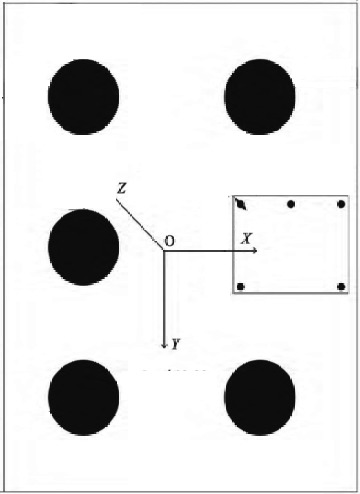
Diagram of cooperative target for microsatellite rendezvous and docking pose measurement
The light source can also be used for the design of feature points. In the Shenzhou 8 spacecraft and Tiangong 1 space station rendezvous and docking with the cooperative target using target marker lamp autonomous light. The camera takes direct imaging measurements of them. Its advantages are active target marker image spot uniform, stable, high measurement accuracy, high reliability of target identification [7]. From the perspective of easy image point extraction, easy identification and mass centre calculation, the shape of the marker lamp was chosen as circular, and the engineering realisability of the target lamp was also considered in the design process.
-
(2)
Passive Targets
Passive targets are generally composed of materials such as coatings, cone corner prisms and glass beads, and the choice of material is determined by the application scenario, light source characteristics, etc.
-
1)
Coatings
Coated pattern targets are generally used in well-light scenes, which have diffuse reflective properties and can be used in visible or infrared light detection systems, depending on the coating material.
Target patterns with a high-contrast composition of light and dark colors (mainly black and white) and with internal and external contours are more widely used. Corner feature colors should stand out relative to the background color for easy identification, usually with black or white coatings or colored coatings filling the target shape, which are easy to segment relative to the background color. Zhang Bin et al. [8] designed a room-type black-and-white target pattern, as shown in Fig. 3, and obtained pose data of the cargo platform module by detecting the pattern target to make a smooth landing of airborne equipment dropped from a long distance.
Fig. 3. 
Diagram of cooperative targets for airdrop systems
Coated pattern targets are widely used in UAV autonomous landing applications. In the design of UAV visual localisation and navigation in a strong denial environment, Gao Hailing et al. [5] designed a “concave” target, as shown in Fig. 4. The “concave” interior of the cooperative target, except for the circular area, is designed with black infrared paint, which makes the cooperative target significantly different from the surrounding environment and can assist the infrared sensor in the visual navigation system to achieve autonomous landing of the UAV in poor lighting conditions. The design of the circle inside the cooperative target as blue enables the extraction of the target based on color threshold processing method only when extracting the circle inside the cooperative target at close range.
Fig. 4. 
Diagram of cooperative target for UAV visual localisation and navigation
Ni Lixue et al. [9] used an infrared thermal imaging camera as an unmanned airborne vision system and designed a long cross-shaped cooperative target to guide the UAV landing using the long side in line with the landing direction. A black infrared coating with an emissivity of ε > 0.92 and corresponding to a wavelength band of 8–14 μm prepared from a high emissivity powder was chosen to be sprayed on the surface of the cooperative target to improve the thermal radiation efficiency (Fig. 5).
Fig. 5. 
Diagram of a drone infra-red locating a cooperative target
The above coated targets are filled with color paint or infrared paint inside the pattern, making the target significantly different from the environmental background and facilitating target extraction. At the same time the design of the coated target needs to take into account the need for water resistance and subsequent cleaning and maintenance. The coated target design is widely used in the field of autonomous landing position measurement for UAVs, as well as in civil applications such as industrial mating and positioning systems and medical navigation and positioning systems.
-
2)
Cone corner prism
The cone corner prism has high reflectivity and good directionality of the reflected beam in the original direction, and is widely used in laser ranging, lidar and other laser detection technologies.
As shown in Fig. 6, the cone corner prism is a tetrahedron consisting of three mutually perpendicular reflection planes (commonly known as the small plane) and one incident plane (commonly known as the large plane). The cone corner prism allows the incident light to return in its original direction, with the incident and exit rays symmetrical according to the centre of the cone point [10]. The cone corner prism cannot be applied directly as an optical element. Usually the cone corner prism is assembled with a mechanical structure to form an angular reflector.
Fig. 6. 
Schematic diagram of an cone corner prism
The measurement accuracy of angular cone prisms decreases as the angle of incidence increases, with a sudden change at the maximum permissible angle of incidence [11]. This is why tracking measurements with angular reflectors take into account the effect that changes in the angle of incidence have on the measurement accuracy. The relationship between the effective reflective area of an angular reflector and the incident angle of the beam is usually analysed to obtain the relationship between the measurement accuracy of an angular reflector and the angle of incidence.
With the characteristics of directional reflection of the angular reflector, the laser angular reflector can be used on satellites and launch vehicles to achieve accurate ranging and effective tracking and orbiting of high-speed moving satellites and other targets, detected by the laser detection equipment [12].
In the rendezvous and docking of Shenzhou XI and Tiangong II space stations, angular cone prisms are used as passive targets. The cooperative targets include far-field, near-field and super-near-field targets, of which the near-field and super-near-field targets are mounted to the target vehicle after forming a three-dimensional target assembly through a common mount. The far-field target marker also contains six angular reflectors, which are mounted directly to the target vehicle according to certain geometric position relationships [13].
Foreign rendezvous and docking missions also mostly use angular reflector arrays, such as the US MSFC in the Orbital Express autonomous rendezvous and docking mission using the Advanced Video Guidance Sensor, whose cooperation target is shown in Fig. 7a. The French company Sodern is using a Video Guidance Sensor (Videometer) for the Orbital Express autonomous rendezvous and docking mission, with the collaboration objectives shown in Fig. 7b.
Fig. 7. 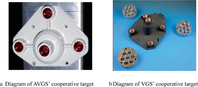
Diagram of cooperative target for the rendezvous and docking
Corner reflectors on laser ranging satellites are usually distributed in spherical, hemispherical or planar shapes.Spherical and hemispherical shapes mostly used on low-orbiting satellites and planar shapes mostly used on high-orbiting satellites. For example, the Russian low-orbit high-precision laser ranging satellite WESTPAC-1 carries 60 angular reflectors in spherical form, the low-orbit scientific satellite ADEOS Earth observation satellite carries 9 angular reflectors in hemispherical form, and the US high-orbit GPS satellite carries 32 angular reflectors in planar form, as detailed in Fig. 8 [14].
Fig. 8. 
Diagram of cooperative target for Laser Ranging Satellite
-
3)
Glass beads
Glass beads are glass spheres with diameters ranging from a few microns to a few hundred microns and have primary reflective properties. Glass beads with high reflectivity need to have a refractive index of not less than 1.93, an ellipsoidal index of not more than 5%, no precipitation in the glass beads, and no impurities mixed with them [15]. At present, the domestic bead forming process is realized by using negative pressure system and gasification chamber, which can meet the above index requirements.
The bead glass original directional reflective screen is composed of glass beads coated on pressure-sensitive adhesive film, and then pasted onto the flat plate. The structure is illustrated in Fig. 10. If the subsequent surface is coated with aluminium or silver film, the reflective brightness can be greatly improved. The effective angle of the glass beads can reach ±70°, reflectivity of them is about 20%, the main reflection area reflection dispersion angle of about 1°, the maximum dispersion angle can reach 3–5°. Compared with cone corner prisms, glass beads have the advantages of low cost, light weight, easy installation and no change in the shape of the equipment, but the disadvantage is that their reflected beam dispersion angle is larger, and the reflectivity is lower [10] (Fig. 9).
Fig. 9. 
The structure of glass beads original directional reflection screen
The glass bead primary reflective structure is available in flat and spherical shapes, as shown in Fig. 10. The planar shape has circular and coded patterns, and can be fixed by pasting, which does not take up dimensional space and is convenient and simple. The spherical shape requires mechanical fixation and takes up dimensional space, but the measurement field of view is large and the measurement accuracy is relatively high compared to the planar shape. The glass bead material is widely used in industrial, medical and aerospace fields.
Fig. 10. 
Diagram of the primary reflection structure of glass beads
-
1)


3.3 Summary
The above describes the current state of cooperative target technology from the perspective of the types of cooperative targets, and clarifies that the selection and design of cooperative targets need to be determined according to indicators such as illumination mechanism, application scenario, accuracy requirements and cost. Coatings, cone corner prisms and glass beads are the main application materials of passive cooperative targets at present, among which cone corner prisms and glass beads have in-situ reflection characteristics and are widely used.
4 Conclusion
Cooperative targets are an important part of the spacial pose measurement system. This paper analyses the principles, methods and the technology state of the cooperative target, which is a reference value for the design of cooperative targets. Different applications determine the shape, size, color and material of the cooperative target. Miniaturisation, light weight and low cost are common requirements for all applications. In the aerospace sector, miniaturisation and lightweighting have been the focus of cooperative target technology due to resource constraints. In special applications, such as medical and steel mills, where the cooperative target is consumables, low cost design is the focus of collaborative target design. This shows that miniaturisation, lightweighting and low-cost design will become increasingly important in cooperative target technology, while meeting the technical level of simplicity, high machining accuracy and high stability.
References
Wu, Y.: Study of cooperative target-based UAV positioning with monocular vision problem. Nanjing University of Science and Technology, Nanjing (2017)
Zhang, L.: Cooperative design method in microsatellite rendezvous and docking pose measurement. Chin. J. Liq. Cryst. Displays 33(3), 415–424 (2022)
Lu, Y.: Research on mono-vision pose measurement for space cooperative target. University of Chinese Academy of Sciences, Beijing (2018)
Chen, Y.: Novel landmark design of autonomous landing in unmanned aerial vehicle. J. Univ. Electron. Sci. Technol. China 45(6), 934–938 (2016)
Gao, H.: Vision aided localization and navigation for unmanned aerial vehicle in GPS-denied environment. Xidian University, Xian (2018)
Qu, Y.: Graphics design of cooperative targets on monocular vision high precision measurement. Acta Opt. Sin. 40(13), 1315001–1–1315001–8 (2020)
Zhao, C.: A vision guidance sensor for Shenzhou-8 spacecraft autonomous. Aerosp. Control Appl. 37(6), 6–14 (2011)
Zhang, B.: A vision-based method for solving heading attitude of airdrop cargo platform. Tianjin University of Technology, Tianjin (2022)
Ni, L.: Research and design of a sort of cooperative target on the ground. Opto-Electron. Eng. 34(7), 8–13 (2007)
Zhang, D.: A laser cooperative target design with adjustable divergence angle of reflected beam. Technol. Innov. Appl. 13, 99–101 (2018)
Liu, W.: Effect of incident laser beam angle varying on cube corner retro-reflector measurement accuracty. Opt. Precis. Eng. 17(2), 286–291 (2009)
Zhou, H.: Design of satellite laser retro-reflector. Opto-Electron. Eng. 32(11), 25–29 (2005)
Liu, Q.: New generation camera-type rendezvous and docking sensor. Aerosp. Control Appl. 44(2), 56–61 (2018)
Wan, Q.: Current status and progress of laser cooperative targets technology for SLR. Adv. Lasers Optoelectron. 42(5), 20–29 (2005)
Li, H.: Study on divergence characteristics of glass microbeads from retroreflective screen. Transducer Microsyst. Technol. 38(3), 14–16 (2019)
Author information
Authors and Affiliations
Corresponding author
Editor information
Editors and Affiliations
Rights and permissions
Copyright information
© 2023 The Author(s), under exclusive license to Springer Nature Singapore Pte Ltd.
About this paper

Cite this paper
Liu, J., Deng, L., Liu, X., Tao, L. (2023). Current Status and Progress of Cooperative Target Technology for Spatial Pose Measurement. In: Urbach, H.P., Jiang, H. (eds) Proceedings of the 7th International Symposium of Space Optical Instruments and Applications. ISSOIA 2022. Springer Proceedings in Physics, vol 295. Springer, Singapore. https://doi.org/10.1007/978-981-99-4098-1_52
Download citation
DOI: https://doi.org/10.1007/978-981-99-4098-1_52
Published:
Publisher Name: Springer, Singapore
Print ISBN: 978-981-99-4097-4
Online ISBN: 978-981-99-4098-1
eBook Packages: Physics and AstronomyPhysics and Astronomy (R0)