
Abstract
The diagrid is a framework of diagonally intersecting members that are used in the construction of buildings and roofs. It requires a lower percentage of steel than a standard design. The need for columns and can be obviated by the use of diagrids. Diagonal members in the system carry gravity loads as well as lateral forces. Due to the triangulated configuration of members, internal axial forces arise in the members, in turn minimizing shear racking effects. Diagrid structures are generally used in the construction of high-rise buildings as lateral forces get minimized. The primary goal of the research is the design and analysis of diagrid structural systems for the high-rise buildings. The modeling was done by using PATRAN software and was analyzed using NASTRAN software. The study includes analysis of the representative models of various geometric forms for optimal construction in terms of strength, stiffness, aesthetic appearance, material requirement, and low cost. The investigations also include the study of the optimal cross section of diagrid members. A quasi-static environment and geometric nonlinear analysis are considered in the analysis of diagrid structures.
Access provided by Autonomous University of Puebla. Download conference paper PDF
Keywords
1 Introduction
The advancements in the construction of high-rise buildings have led to the implementation of diagrid structures. In the olden times, high-rise buildings were of typical portal frame systems with horizontal beams and vertical columns. Later on, additional bracings were introduced in order to take up the lateral loads more efficiently than that in the conventional building frame systems. The major difference of a diagrid building in comparison with a braced tube building is the absence of vertical columns in the system. With a lower requirement and maximum exploitation of materials, diagrid structures exhibit their effectiveness in contrast to conventional and braced frames.
Diagonal members in diagrid structures act both as inclined columns and as bracing elements, thus carrying both gravity loads as well as lateral forces. With the axial action of diagonal members, it takes up the shear acting on it, thus reducing the shear racking effects. The unique geometric configuration of the system enhances structural stability along with the aesthetic appeal. It provides for a sustainable structure with greater stiffness and structural efficiency. Redundancy in the diagrid design helps in the transfer of load from a failed portion of the structure to another. A diagrid has better ability to redistribute load than a moment frame skyscraper, creating a deserved appeal for the system.
The most commonly used material for the diagrid construction is steel and the system can be applied for various geometric forms. Geometric nonlinearities have led to the evolution of diagrid projects with hyperboloid, aerodynamic, cylindrical, irregular, twisted, tapered, tilted, and free forms, the most challenging among them being “twisted”. Examples for diagrid structures with the common geometric forms are the steel diagrids that can be created using modern 3D modeling software, as the mesh conforming to almost any shape is possible. With the redundancy factor, unusual structures and complex geometries have become possible for the system.
The goal of this paper is to analyze and compare the geometric nonlinearity on diagrid structural systems. The different geometrical shapes considered are building plan sections of square, triangular, and circular. Each shape of the building is analyzed for lateral displacements by varying the cross sections of the members. The different cross-sectional geometries considered are rectangular, circular, hollow circular, and I-section. The study is carried out to obtain the optimal geometries for the building and cross section.
2 Objectives of the Study
The objectives of the study include the following:
-
To analyze the representative models of various geometric forms for optimal construction in terms of strength, stiffness, aesthetic appearance, material requirement, and low cost
-
To study the optimal cross section of diagrid members.
3 Analysis of Diagrid Buildings
Geometrical nonlinear analysis of G+26 story buildings with a plan area of 625 m2 is modeled using PATRAN software and analyzed using NASTRAN software considering the seismic behavior of the structure. Buildings of square, triangular, and circular plans are considered with varying member cross sections of rectangle, circle, hollow, and I-sections.
3.1 Structural Models
Regular structures with the same cross-sectional areas are considered for the analysis. G+26 buildings of 75.75 m height, with a story height of 2.75 m and a footing height of 1.5 m is modeled in PATRAN software.
Plan dimensions of buildings with different geometrical forms are as follows:
-
Square: 25 m × 25 m, shown in Fig. 1
Fig. 1 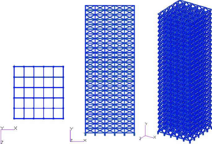
Plan, elevation, and 3D model of square building
-
Triangle: Side, a = 38 m, shown in Fig. 2
Fig. 2 
Plan, elevation, and 3D model of triangular building
-
Circle: Diameter, Φ = 28 m, shown in Fig. 3.
Fig. 3 
Plan, elevation, and 3D model of circular building


Member cross sections are modeled for beam cross section to be 80,000 mm2, diagrid cross section to be 90,000 mm2, and footing cross section to be 36,0000 mm2, and are as follows:
-
Rectangle: For beams—200 mm × 400 mm
For diagrid—300 mm × 300 mm
For footings—600 mm × 600 mm
-
Circle: For beams—319.154 mm Φ
For diagrid—338.514 mm Φ
For footings—677.028 mm Φ
-
Hollow circle: For beams—Φ1 = 382 mm, Φ2 = 210 mm
For diagrid—Φ1 = 380 mm, Φ2 = 172 mm
For footings—Φ1 = 720 mm, Φ2 = 245 mm
-
I-section: For beams—Total height, H = 500 mm
Flange width, W = 300 mm
Web thickness, tw = 78 mm
Flange thickness, tf = 92 mm
-
For diagrid—Total height, H = 500 mm
Flange width, W = 300 mm
Web thickness, tw = 78 mm
Flange thickness, tf = 92 mm
-
For footings—Total height, H = 500 mm
Flange width, W = 300 mm
Web thickness, tw = 78 mm
Flange thickness, tf = 92 mm
-
3.2 Material Properties
Material properties of steel are given as follows:
-
Density of steel = 7800 kg/m3
-
Young’s modulus = 2.1 × 10⁵ N/mm2
-
Poisson’s ratio = 0.3
3.3 Loads and Boundary Conditions
Boundary conditions are provided as fixed at the base.
Dead load value for the roof is given as 1.5 kN/m2 and for all other floors as 4.5 kN/m2.
Live load values for all floors are given as 4 kN/m2.
Earthquake loads are calculated as per IS 1893(Part1):2002.
6 load cases and 13 basic load combinations were considered for the study.
3.4 Analysis Results
Analysis results were taken based on lateral displacement as shown in Figs. 4, 5, 6, 7, 8, 9, 10, 11, 12, 13, 14 and 15.

Maximum lateral displacement obtained for square building with rectangular cross section

Maximum lateral displacement obtained for square building with circular cross section

Maximum lateral displacement obtained for square building with hollow circular cross section

Maximum lateral displacement obtained for square building with I-section

Maximum lateral displacement obtained for triangular building with rectangular cross section

Maximum lateral displacement obtained for triangular building with circular cross section

Maximum lateral displacement obtained for triangular building with hollow circular cross section

Maximum lateral displacement obtained for triangular building with I-section

Maximum lateral displacement obtained for cylindrical building with rectangular cross section

Maximum lateral displacement obtained for cylindrical building with circular cross section

Maximum lateral displacement obtained for cylindrical building with hollow circular cross section

Maximum lateral displacement obtained for cylindrical building with I-section
4 Conclusions
The conclusions obtained are the following:
-
The minimum lateral displacement is obtained for square building and is maximum for triangular building.
-
The maximum displacements are obtained at load case 1.5 (DL+ELZ−) for square and circular buildings and is 1.5 (DL+ELZ) for triangular building.
-
Buildings of members with circular cross section show the minimum displacement and with rectangular cross section shows the maximum displacement.
References
Akshat GS (2018) Dynamic analysis of diagrid structural system in high rise steel buildings. Int J Civil Eng Technol 9(8):71–79
Pattar CS, Gokak SV (2018) Analysis of diagrid structures with plan irregularity. Int Res J Eng Technol 5(8):435–438
Panchal NB, Patel VR (2018) Diagrid structural system: strategies to reduce lateral forces on high-rise buildings. Int J Res Eng Technol 3(4):374–378
Yadav S, Garg DV (2018) Advantage of steel diagrid building over conventional building. Int J Manag Technol Eng 3(1):394–406
Rai AK, Sakalle R (2017) Comparative analysis of a high rise building frame with and without diagrid effects under seismic zones III & V. Int J Eng Sci Res Technol 6(9):95–101
Gopisiddappa D, Divyashree M, Sindhuja GJ (2017) Performance study of high rise building with diagrid system under dynamic loading. Int Res J Eng Technol 4(6):2690–2695
Szolomicki J, Golasz-szolomicka H (2017) Application of the diagrid system in modern high-rise buildings. Int J Adv Sci Eng Technol 5(3):7–13
Pawar SV, Kakamare MS (2017) Earthquake and wind analysis of diagrid structure. Int J Res Appl Sci Eng Technol 5(7):1729–1739
Nawale UA, Kakade DN (2017) Analysis of diagrid structural system by E-Tab. Int Adv Res J Sci Eng Technol 4(6):193–196
Varkey D, George M (2016) Dynamic analysis of diagrid system with complex shape. Int J Innov Sci Eng Technol 3(8):484–488
Shah MI, Mevada SV, Patel VB (2016) Comparative study of diagrid structures with conventional frame structures. Int Res J Eng Technol 6(5):22–29
Philip NG, Shashidharan D (2016) Analysis of circular steel diagrid buildings with non-uniform angle configurations. Int J Sci Eng Res 7(10):296–303
Bhale P, Salunke PJ (2016) Analytical study and design of diagrid building and comparison with conventional frame building. Int J Adv Technol Eng Sci 4(1):226–236
Kamath K, Ahamed N (2015) Effect of aspect ratio on performance of diagrid structure circular in plan. Int J Earth Sci Eng 8(2):411–416
Raghunath D, Deshpande SM, Patil SR (2015) Analysis and comparison of diagrid and conventional structural system. Int Res J Eng Technol 2(3):2295–2300
Khan R, Shinde SB (2015) Analysis of diagrid structure in comparison with exterior braced frame structure Int J Res Eng Technol 4(12):156–160
Revankar RK, Talasadar RG (2014) Pushover analysis of diagrid structure. Int J Eng Innov Technol 4(3):168–174
Singh RK, Garg V, Sharma A (2014) Analysis and design of concrete diagrid building and its comparison with conventional frame building. Int J Sci Eng Technol 2(6):1330–1337
Jani K, Patel PV (2013) Analysis and design of diagrid structural system for high rise steel buildings. Proc Eng 51(19):92–100
Mascarenhas DP, Aithal DS (2012) Study on diagrid structures with various aspect ratio under the action of wind. Int J Adv Res Ideas Innov Technol 3(4):521–526
Author information
Authors and Affiliations
Corresponding author
Editor information
Editors and Affiliations
Rights and permissions
Copyright information
© 2021 Springer Nature Singapore Pte Ltd.
About this paper

Cite this paper
Jacob, S.M., Phani Charan, N., Raju, A. (2021). Design and Analysis of Diagrid Structural Systems for High-Rise Buildings. In: Singh, R.M., Sudheer, K.P., Kurian, B. (eds) Advances in Civil Engineering. Lecture Notes in Civil Engineering, vol 83. Springer, Singapore. https://doi.org/10.1007/978-981-15-5644-9_17
Download citation
DOI: https://doi.org/10.1007/978-981-15-5644-9_17
Published:
Publisher Name: Springer, Singapore
Print ISBN: 978-981-15-5643-2
Online ISBN: 978-981-15-5644-9
eBook Packages: EngineeringEngineering (R0)