
Abstract
Deep excavation is an indispensable part of constructions on subsoil in Hanoi, Vietnam. There are 8 urban railways which were constructed with many deep foundations in the main terminals in Hanoi. The 8th terminal at the Nhon – Hanoi Station route is more complex than others due to the configuration of the terminal. The terminal is about 8 m deep. Bored piles with 1.2 m in diameter were constructed at the bottom of the pit. In order to ensure stability of the pit, Larsen IV steel sheet piles were constructed with a length of 12 m. In addition, two rows of soil anchors with 14 m in length and 15.2 mm in diameter have also been adopted to strengthen the foundation pit.
Analytical method using the Geo5 program was conducted to design the steel sheet piles at the site. Numerical method using the Plaxis program was also conducted to verify the design of the steel sheet piles. In the analytical analysis, exact solutions are obtained by solving differential equations directly with some assumptions and limitations, meanwhile in the numerical analysis the derivatives in different equations are replaced by some sort of approximation and solutions. Comparison of the deformation of steel sheet piles, internal forces on the piles, and internal forces on the anchors obtained from the analytical and numerical methods were provided in the paper. It was concluded that the predicted values obtained from the analytical method should be more conservative than those obtained from the numerical analysis.
Access provided by CONRICYT-eBooks. Download conference paper PDF
Keywords
1 Introduction
According to planning, there will have 4–5 urban railways in Hanoi. The 3rd route starts from Nhon to Hanoi Station. The project with the full length of 12.5 km contains 9.6 km elevated and 2.9 km underground. Correspondingly, there are 11 elevated terminals and 4 underground terminals. Designed length of the train is 19 to 20 m. The speed is 80 km/h.
The 3rd route has connected stations. In which, the 8th terminal is located in front of University of Transport and Communications, includes main bus station with a large traffic volume. During the construction of the foundation pit for piers of the terminal, Larsen IV steel sheet piles combined with ground anchors were proposed to stabilize the pit.
The 8th terminal at the Nhon – Hanoi Station route is deeper and more complex than others due to the configuration of the terminal that requires appropriate construction methods as well as calculations.
Soil anchors have been applied for deep excavations in many projects all over the world (Briaud and Lim 1999; Weatherby 1998). The anchors are often combined with steel sheet piles to strengthen the excavation (Harris and Bond 2008; Weatherby 1998). They are installed to transfer a tension load in bearing strata that can be soil or rock. The specifications for the soil anchor calculations are sufficient such as BS 8081 (1989), AASHTO LRFD 2007 (SI version) or LRFD 2012.
For transportation projects, the AASHTO LRFD is normally applied. However, projects with the anchors in urban transportation in Vietnam are not mentioned, this paper introduces an example for the soil anchor in the urban railway project.
In the project, Geostructure analysis (Geo5 v19) was used to calculate and audit the steel sheet pile structure with the ground anchors. Using Geostructure Analysis software (Bentley-US) allows the calculation in construction stages, taking into account both internal stability and overall stability of the structure. In which, Sheeting check function is suite for making basic design of the required length of the structure, calculating the internal forces or verifying the cross-sections based on traditional analytical methods.
Plaxis 2D was used to compare to Geo 5 program. Plaxis 2D is one of the most powerful tools for geotechnical engineers. It is a finite element program package specifically intended for the analysis of deformation and stability in geotechnical engineering projects. Although the modeling of the soil itself is an important issue, many projects involving the modeling of structures and the interaction between structures and soils would be analyzed in Plaxis 2D.
2 Designation and Instructions
2.1 General on the Project
The main document is technical design documentation of foundation measures for the project “Pilot Urban Railway in Hanoi: Nhon - Hanoi Station Section” by investor: Hanoi People’s Committee - Hanoi Public Transport and Tram Development Management Board.
In order to construct a pillar platform, design consultant uses Larsen piling method around the pit and proceeds to excavate the soil in the foundation pit, finally build the platform. Due to the large depth of excavated soil, the pile wall near the elevated road has stabilized by the soil anchors (Fig. 1).


Cross section of the foundation pit at the 8th terminal
At the 8th terminal, both the 12 m-long-steel sheet piles and the 12 m-long anchors are installed. Spacing between the anchors is 2 m.
2.2 Input Parameters
2.2.1 Traffic Load
Load due to vehicles acting on one side of Thu Le park is calculated with a designed truck with an axial load of 145 kN.
The designed truck is shown in Fig. 2 below. The traffic range is 8.5 m, each separated by 1.2 m. In addition, construction load such as excavator and crane load are also considered. All construction and traffic load are calculated and shown in Table 1. From the calculations, we select q = 42.65 kN/m2 for the excavation design (Fig. 3).


The designed truck


The truck layout
2.2.2 Geological Conditions
There are 4 layers in the scope of calculation. The top layer is DD layer including concrete, brick, sand and clay, thickness is 3.97 m; Made ground layer: backfill, silty sand, thickness is 0.8 m; GU1_s layer: lean clay with some organic, firm to stiff, thickness is 6.7 m; GU3&4 layer: Fat and elastic (CH-MH) + Organic matter, thickness is 2 m. Properties of the layers are described in Table 2.
2.3 Materials
2.3.1 Larsen IV
Steel type for Larsen IV is CT3, detail properties are as follow (Table 3):
2.3.2 Anchor
Geometric features of anchor cables: Use 2 cables 15.2 mm (Tables 4 and 5).
2.3.3 Scopes of the Calculation
-
Checking of the sheet piles L = 12 m in construction stages
-
Checking of the ground anchors
3 Analytical Analyses
Calculate and check the sheet piles L = 12 m and the ground anchors in construction stages by using Geo5:
-
Stage 1 Pressing the sheet pile (L = 12 m). Excavate to ground anchor elevation +8.508 (Fig. 4).
Fig. 4. 
Model of foundation pit in Geostructure analyses in stage 1
-
Stage 2 Install the ground anchors (Fig. 5).
Fig. 5. 
Model of foundation pit in Geostructure analyses in stage 2
-
Stage 3 Excavate to bored pile elevation +7.245 (Fig. 6).
Fig. 6. 
Model of foundation pit in Geostructure analyses in stage 3
-
Stage 4 Excavate to wale and struts elevation. Install wale and struts at elevation +6.986, frame fixed frame support and cofferdam by welded (Fig. 7).
Fig. 7. 
Model of foundation pit in Geostructure analyses in stage 4
-
Stage 5 Excavate to bottom blinding concrete elevation +2.953 (Fig. 8).
Fig. 8. 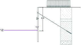
Model of foundation pit in Geostructure analyses in stage 5


4 Numerical Analyses
Numerical analyses were performed to study the lateral movement and forces of the steel sheet piles. Mohr-Coulomb model is used in the analyses in order to simulate the behavior of the soil layers. Figure 9 shows mesh of the excavation domain in the final stage of the construction with the construction load at one side of the excavation pit.


Deformed mesh at final stage of the construction
5 Results
5.1 Analyses Results
-
Stage 1 Press sheet piles (L = 12 m). Excavate to the ground anchor elevation +8.508 (Fig. 10).
Fig. 10. 
Diaphragm of bending moment, shear force and displacement at stage 1
-
Stage 2 Install the ground anchors (Fig. 11).
Fig. 11. 
Diaphragm of bending moment, shear force and displacement at stage 2
-
Stage 3 Excavate to bored pile elevation +7.245 (Fig. 12).
Fig. 12. 
Diaphragm of bending moment, shear force and displacement at stage 3
-
Stage 4 Excavate to wale and struts elevation. Install wale and struts at elevation +6.986, frame fixed frame support and cofferdam by welded (Fig. 13).
Fig. 13. 
Diaphragm of bending moment, shear force and displacement at stage 4
-
Stage 5 Excavate to bottom blinding concrete elevation +2.953 (Fig. 14).
Fig. 14. 
Diaphragm of bending moment, shear force and displacement at stage 5


5.2 Checking for Steel Sheet Pile
Maximum bending moment and shearing force values will be used to check the cross section of the sheet piles (Table 6).
Cross section of piles ensures the bearing capacity. At the same time, the horizontal displacement of the pile is small, meets the allowable displacement of the anchor pile wall.
5.3 Checking for Ground Anchor
The anchor force values during the construction stages analysed in Geo5 and Plaxis are shown in Table 7.
The length of the ground anchors L = 12 m, meet the requirements of bearing capacity.
6 Discussions
The procedure for deep foundation design using the steel sheet piles in combination with the ground anchors was presented in detail. Based on the results, the following conclusions can be drawn:
-
The calculated results are quite compatible in Geo5 and Plaxis.
-
The bending moments and shear forces in Plaxis agreed with the calculated results in Geo5 for each construction stage.
-
The displacements at the toe of steel sheet pile tend to be larger and at the head of sheet pile are smaller in Plaxis compare to Geo5.
-
The internal force values in Geo5 are more conservative than in Plaxis.
The differences between analytical and numerical analyses in the lateral movement of the sheet piles and the ground anchors can be explained by the differences of modulus parameters. In details, the moduli used in Geo5 were deformation moduli that were determined by the in-situ tests. Meanwhile, the moduli used in Plaxis were elastic modulus obtained from laboratory tests.
7 Conclusions
Both analytical and numerical analyses can be used successfully in analyses of steel sheet pile for deep excavation. The results of those analyses show good agreement in the internal forces of the piles for stages of construction.
Analytical analysis with the sheeting check function can be easily used with in-situ tests. Meanwhile, numerical analysis with sophisticated boundary conditions should be used in routine design and construction of steel sheet pile excavation.
This paper summarized the results of calculating internal force and displacement of steel sheet pile in stages and the method of anchored auditing in the soil applied to deep foundation in urban works.
References
AASHTO LRFD: Bridge Design Specifications, SI version (2007)
AASHTO LRFD: Bridge Design Specifications, 6th edn. (US) (2012)
Briaud, J.L., Lim, Y.: Tieback walls in sand: numerical simulation and design implications. J. Geotech. Geoenviron. Eng. 125(2), 101–111 (1999)
BS 8081: Code of practice for ground anchorages (1989)
Harris, A., Bond, A.: Decoding Eurocode 7. Taylor & Francis, London (2008)
Project Reference: Elevated stations, Package number: HPLMLP/CP-02, December, 2014
Weatherby, D.E.: Design Manual for Permanent Ground Anchor Walls. Federal Highway Administration, Washington, DC (1998)
Oanh, N.C., Tram, D.T.V., Vinh, T.C.T.: Finite element analysis of a braced excavation in marine soft clay. In: Geotechnics for Sustainable Infrastructure Development - Geotec Hanoi 2016, Phung (edt) (2016). ISBN 978-604-82-1821-8
Author information
Authors and Affiliations
Corresponding author
Editor information
Editors and Affiliations
Rights and permissions
Copyright information
© 2018 Springer Nature Singapore Pte Ltd. and Zhejiang University Press
About this paper
Cite this paper
Lan, N.C., Manh, T.Q. (2018). Comparison of Analytical and Numerical Analysis Results of Deep Excavation for Nhon – Hanoi Urban Railway Project in Hanoi, Vietnam. In: Chen, R., Zheng, G., Ou, C. (eds) Proceedings of the 2nd International Symposium on Asia Urban GeoEngineering. Springer Series in Geomechanics and Geoengineering. Springer, Singapore. https://doi.org/10.1007/978-981-10-6632-0_13
Download citation
DOI: https://doi.org/10.1007/978-981-10-6632-0_13
Publisher Name: Springer, Singapore
Print ISBN: 978-981-10-6631-3
Online ISBN: 978-981-10-6632-0
eBook Packages: EngineeringEngineering (R0)