
Abstract
Wastes are discarded or unwanted materials resulting from the domestic and industrial activities of humans. Wastes carried in water are described as sewage. It is important to determine the quantity of carbon in sewage so as to know the most appropriate method to use for treating it. One of the most common methods is the Biochemical Oxygen Demand (BOD) which measures the oxygen consumed by microorganisms to degrade the carbon over a 5-day period. Other methods are chemical in nature and related to the potential of the microbial breakdown. These chemical methods are the Permanganate Value (PV) Test, the Chemical Oxygen Demand (COD), Total Organic Carbon (TOC), Total Suspended Solids (TSS), and Volatile Suspended Solids (VSS).
Aerobic methods for disposing of sewage are: the Activated Sludge System, the Trickling Filter, the Rotating Disks, and the Oxidation Pond. Anaerobic methods include the Septic Tank, the Imhoff Tank, and Cesspools. Advanced wastewater treatment (AWT) methods are expensive and used for producing water for specialized use. They include: Reverse Osmosis, Nanofiltration, Ultrafiltration and Microfiltration, Electrodialysis, Activated Charcoal, Ion exchange, UV Oxidation, and Precipitation.
Access provided by Autonomous University of Puebla. Download chapter PDF
Keywords
- Activated sludge
- Trickling filter
- Cesspools
- Imhoff tank
- Biochemical Oxygen Demand (BOD)
- Chemical Oxygen Demand (COD)
- Total Organic Carbon (TOC)
- Advanced Wastewater treatment (AWT)
1 Nature of Wastes
Wastes, discarded and unwanted materials, result inevitably from human activities, whether domestic or industrial. If wastes are allowed to accumulate on the ground, or if dumped indiscriminately into rivers and other bodies of water, unacceptable environmental problems would result (Eckenfelder 2000). Wastes are therefore disposed of in order to reduce their harmful effects on the environment. Three approaches are used:
-
(a)
The wastes may be concentrated and isolated from the normal environment. For example, small amounts of highly toxic wastes may be concentrated and dumped into the depths of the ocean; human excreta may be isolated by being buried underground.
-
(b)
The wastes may be diluted in the environment to a concentration at which they are not harmful. An example of this occurs in some developing countries where sewage is not treated but is diluted by introduction through pipes far into the sea.
-
(c)
Finally, the wastes may be treated mechanically, biologically, or chemically to render them harmless. The materials resulting from such treatments are expected to meet standards laid down by authorities set up in various countries to monitor such activities. For instance, the US Environmental Protection Agency (USEPA) has set standards which sewage treatment effluents must meet regarding bacterial numbers in domestic sewage and chemicals in case of industrial sewage (see below).
Governments the world over institute legislation which regulates the handling of wastes, including those resulting from industry. In the US, the USEPA works to develop and enforce regulations that implement environmental laws enacted by the Congress. EPA is responsible for researching and setting national standards for a variety of environmental programs, and delegates to states the responsibility for issuing permits, and for monitoring and enforcing compliance (Anonymous 2004).
Wastes may be carried in water (sewage) or may be solid (municipal solid wastes, MSW). This chapter will discuss some of the methods used in treating sewage. Chapter 11 will discuss the treatment of MSW.
2 Methods for the Determination of Organic Matter Content in Sewage and Wastewaters
Sewage is the water borne wastes of human activities, both domestic and industrial. The water borne wastes generated by some 60% of the US population are collected in sewer systems and carried by some 14 billion gallons of water a day before being treated. The rest receives some form of treatment to improve the quality of the water before it is released for reuse. Of this volume, about 10% is allowed to pass untreated into rivers, streams, and the ocean.
Wastewaters are sampled and analyzed in order to determine the efficiency of the treatment system in use. This is particularly important at the point of the discharge of the treated wastewater into rivers, streams, and other natural bodies of water. If wastewater discharged into natural water is rich in degradable organic matter, large numbers of aerobic micro-organisms will develop to break down the organic matter. They will use up the oxygen and as a consequence, fish and other aquatic life which require oxygen will die. Furthermore, anaerobic bacteria will develop following the exhaustion of oxygen; the activities of the latter will result in foul odors. Some of the methods for analyzing the organic matter content of wastewaters are given below (Andrew 1996; Anonymous 2006).
2.1 Determination of Dissolved Oxygen
Dissolved oxygen (DO) is one of the most important, though indirect, means of determining the organic matter content of waters. The heavier the amount of degradable material present in water, the greater the growth of aerobic organisms and hence the lesser the oxygen content. The Winkler method is widely used for determining the oxygen in water. In this method, dissolved oxygen reacts with manganous oxide to form manganic oxide. On acidification in an iodide solution, iodine is released in an amount equivalent to the oxygen reacting to form the manganic oxide. The iodine may then be titrated using thiosulphate. Membrane electrodes are now available for the same purpose. In these electrodes, oxygen diffuses through the electrode and reacts with a metal to produce a current proportional to the amount of oxygen reacting with the metal.
2.1.1 The Biological or Biochemical Oxygen Demand Test
-
1.
The Dilution Method
In the Biochemical Oxygen Demand (BOD) procedure (El-Rehaili 1994), two bottles of 250–300 ml. capacity and with ground-glass stoppers are thoroughly washed with chromic acid mixture and dried before use. They are filled with a suitable dilution of the sewage or water whose BOD is to be determined (Anonymous 2006). The dissolved oxygen in one is determined immediately and in the other after five 5 days’ incubation at 20°C. The difference, the loss of oxygen during incubation, is the BOD, i.e., a measure of oxygen consumed during the stabilization of the organic materials present. As a precaution to prevent the entry of air, special BOD bottles having flared mouths are used; water is added to the flared mouths.
Alternately, the tightly sealed bottles may be inverted in a water bath. The bottle is incubated in a water-bath set at 20°C or preferably in a cooled incubator. Light is prevented from reaching it so that algae present in it may not produce O2 during photosynthesis and thence give wrong results.
The water or sewage whose BOD is to be determined is usually so diluted that the BOD is not more than 5.0 mg/l. The amount of dilution is worked out of experience. The dilution water is usually pure distilled water, but de-ionized water is preferable. The water is aerated by bubbling O2 through it for a few hours before use or by leaving it in a half-filled jar loosely stoppered with cotton wool for about 3–5 days.
It is often necessary to introduce a pure or mixed culture of micro-organisms to (i.e. “seed”) the diluted water, when, as in the case of drinking water, the microbial population is low. The seed used in determining the BOD of drinking water may consist of 1–10 ml of settled domestic sewage or a drop of lactose broth containing an active culture which is known to produce a positive, presumptive coliform test. The amount of seed chosen should give at least 0.6 mg/l after 5 days’ incubation. Seeding may also be done when the material is an industrial waste with no known population capable of breaking it down. The seed for such an industrial waste may be developed in the laboratory by bubbling O2 through a culture, obtained from soil or sewage and grown in the industrial waste. The seed may then be added to the diluted water.
The chemical procedure of the test is a determination of dissolved oxygen (DO) using the Winkler method employing the Rideal–Stewart modification or the Alkaline-Azide modification (also known as Alsterbury [azide] modification). The last term is usually used.
The principle of the test is that manganous hydroxide is oxidized to manganic hydroxide in a highly alkaline solution. When the set-up is acidified in the presence of iodine, the manganic hydroxide dissolves and the free iodine is liberated in an amount equivalent to the O2 originally dissolved in the sample. The free iodine is titrated with a sodium thiosulphate standard solution using starch as, an indicator.
$$ \text{2Mn(OH}{)}_{2}+{\text{O}}_{2}\to \text{ 2Mn(OH}{)}_{3}+{\text{H}}_{2}\text{O}$$$${Mn(OH)}_{3}+{{H}}_{2}{{SO}}_{4}\to {Mn(OH)}_{2}+{{MnSO}}_{4}+{{O}}_{2}$$$$ {\text{O}}_{2}+\text{ KI }+{\text{H}}_{2}\text{O}\to.\text{ KOH }+{\text{I}}_{2}$$The normality of the thiosulphate solution is so adjusted that 1 ml is equivalent to 1 mg/l dissolved O2 when 200 ml of the original sample is titrated, i.e., an N/160 standard solution.
The aim of this discussion has been to examine the concept and principles of BOD. The practical details of the determination will be found in Standard Methods for the Examination of Waters and Waste Waters. 21st edition (Anonymous 2006) and International standards for Drinking Water (WHO).
Microbial Activity and the BOD Test
The breakdown of organic matter in sewage and other waters takes place slowly and is not usually complete in the standard 5-day period of incubation, except for easily oxidized materials such as glucose. Domestic sewage is only about 65% oxidized at this period and industrial sewage might be 40% or less. The BOD required for the breakdown of all stabilizable organic matter is the ultimate BOD (UOD or UBOD). In sewage and industrial wastes, it appears, as has been shown earlier, that the first-order reaction rate is followed at the early stages. In a first-order reaction, the rate is directly proportional to the concentration of the reacting substances.
Before stabilization is complete, the BOD is known to be exerted at two stages. The first demand is used to break down the carbonaceous matter. The second is that in which nitrification of nitrogen-containing compounds occurs.
$$ \begin{array}{l}{\text{2NH}}_{3}+3{\text{O}}_{2}\underset{\text{bacteria}}{\overset{\text{nitrifying}}{\to }}{\text{2NO}}_{2}+2{\text{H}}^{+}2{\text{H}}_{2}\text{O}\\ {\text{2NO}}_{2}+{\text{O}}_{2}+2{\text{H}}^{+}\underset{\text{bacteria}}{\overset{\text{Nitrifying}}{\to }}{\text{2NO}}_{3}+2{\text{H}}^{+}\end{array}$$With raw sewage, nitrification is not important until the 8th to 10th day, because of the slow growth of the bacteria. In practice, the shape of the 5-day BOD curve is not affected by nitrification.
In effluents from sewage treatment plants, nitrification can be evident in 1 or 2 days due to the large number of nitrifying bacteria already present. When therefore the BOD of treated effluents is to be determined, thiourea or TCMP (2-chloro-6 (trichloromethyl) pyridine is added to inhibit nitrification, so that only BOD due to carbonaceous breakdown is determined.
Nitrification is the process in which ammonia is converted first into nitrites and later into nitrates as shown in the equations above. It occurs not only in water but also in soil. Although it can be brought about by a few heterotrophs, nitrification is brought about mainly by autotrophic bacteria. The bacteria derive energy needed for transforming (reducing) CO2 into organic material not with energy from light as in photosynthetic organisms, but by the transfer of electrons from ammonia and nitrites. The organisms involved are small Gram-negative, polarly flagellated rods. The best known of these are Nitrosomonas which oxidizes ammonia to nitrites and Nitrobacter which oxidizes nitrites to nitrates. Others about which much less is known include Nitrosococcus, Nitrospira and Nitrosocystics. They grow slowly and are cultivable on silica gel, but not on agar unless it is specially purified.
Some Criticisms of the BOD Test
Despite its wide use, the BOD test has come under serious criticisms:
-
(a)
When used for sewage disposal studies (especially the aerobic system), the conditions of the BOD are unnatural: The microbial population and the dissolved oxygen are far less than that actually exist during the activated sludge treatment, a major sewage treatment procedure.
-
(b)
The standard 5-day BOD method gives no idea of the rate of O2 uptake, i.e., it gives only the oxygen consumed after 5 days but not from day to day. This criticism has been circumvented by the use of the respirometer. It has been found, using an electrolytic respirometer, that a 3-day BOD at 20°C gave results equivalent to those obtained by the usual method after 5 days.
-
(c)
BOD is only very loosely related to the actual organic matter content of a water, since it represents an overall value of the respiration of a numerically and taxonomically unknown population of micro-organisms, in a medium whose composition is usually unknown.
-
(d)
The assumption that the oxygen consumed is that used by the aerobic bacteria is incorrect. Under natural condition, protozoa use up oxygen within the 5-day period, when at the end of the first 2–3 days bacteria have developed (see Fig. 10.1).
Fig. 10.1 
Typical BOD curve for raw domestic sewage
-
(e)
The BOD test is a static test in a batch culture, whereas the condition in a stream is more like a continuous culture (Eckenfelder 2000).
-
(a)
-
2.
Respirometric Determination of BOD
The standard BOD method described above provides information only at the end of the 5-day period. The single information provided does not offer enough grounds for the computation of the reaction rate and the ultimate BOD.
Since the BOD test is really a measure of oxygen consumption, a respirometer which measures gas volumes is an ideal instrument for its determination. Commercial respirometers study only small volumes of liquid. Attempts have therefore been made to design simple respirometers which will measure relatively large volumes of liquid, with dilute suspensions of organic matter (Standard Methods for the Examination of Water and Waste Water) (Anonymous 2006). Some are available commercially.
Figure 10.2 describes a simple respirometer, which can be constructed in a laboratory workshop with good facilities. It consists of three parts.
Fig. 10.2 
Respirometric method of BOD determination (From Young and Baumann 1976. With permission)
-
(a)
A reaction vessel with a suitable stirrer – e.g., a magnetic stirrer.
-
(b)
An adaptor-unit or container which holds potassium hydroxide or some other suitable CO2-absorbing material.
-
(c)
An electrolysis unit which contains a weak electrolyte, e.g., H2SO4. This unit also serves as a manometer to detect pressure changes and also an oxygen generator to maintain a constant partial pressure in the atmosphere within the sample container.
The respirometer functions by providing semi-continuous and automatic registering, and adjustment of the pressure changes brought about within the reaction vessel because of O2 consumption by microorganisms.
-
(a)
-
3.
Substitutes for the BOD Test
Because of the shortcomings of the BOD test, which is only an indirect measure of the organic matter in water and sewage, many pollution scientists wish to discard it entirely. Indeed the real nature of the BOD test is so often forgotten that one often reads in sanitary engineering textbooks of “BOD removal” – as if BOD were synonymous with organic water.
Two tests which have been suggested as substitutes are the Chemical Oxygen Demand (COD) and a direct measurement of the organic carbon using methods such as the Walkley Black method. The COD is the total oxygen consumed by the chemical oxidation of that portion of organic materials in water which can be oxidized by a strong chemical oxidant. The strong oxidant selected is a mixture of potassium dichromate and sulfuric acid which is refluxed with the sample of water being studied. The excess dichromate is titrated with ferrous ammonium sulfate. The amount of oxidizable organic matter measured as oxygen equivalent is proportional to the dichromate consumed. It is a more rapid test than the BOD and when the water contains materials toxic to micro-organisms, such as in some industrial effluents, it is (along with the determination of total carbon) the only method available to determine the organic load. Unless a catalyst is present, however, it cannot measure a biologically degradable compound such as acetic acid. Furthermore, it measures cellulose which is not easily broken down in water, and certainly not during the 5-day BOD. Where wastes contain readily degradable organic materials and nothing toxic, it can be taken as the UBOD or 20-day BOD.
The direct carbon determination determines the total carbon content of the water including those not ordinarily sampled in the COD determination. A strong chemical oxidant oxidizes all the carbon in the water. The method, therefore, has similar uses to the COD.
Both methods can really not substitute for the BOD determination which measures the easily degradable materials (Anonymous 2006; El-Rehaili 1994).


2.1.2 Permanganate Value Test
This Permanganate Value (PV) method determines the amount of oxygen used up by a sample in 4 h from a solution of potassium permanganate in dilute H2SO4 in a stoppered bottle at 27°C. It gives an idea of the oxidizable materials present in water, although the actual oxidation is only 30–50% of the theoretical value. The method records the oxidation of organic materials such as phenol and aniline as well as those of sulfide, thiosulfate, and thiocyanate and would be useful in some industries. However, because oxidation is incomplete it is not favored by some workers.
2.1.3 Chemical Oxygen Demand
The chemical oxygen demand is the total oxygen consumed by the chemical oxidation of that portion of organic materials in water which can be oxidized by a strong chemical oxidant. The oxidant used is a mixture of potassium dichromate and sulfuric acid and is refluxed with the sample of water being studied. The excess dichromate is titrated with ferrous ammonium sulfate. The amount of oxidizable material measured in oxygen equivalent is proportional to the dichromate used up. It is a more rapid test than BOD and since the oxidizing agents are stronger than that used in the PV test, the method can be used for a wider variety of wastes. Furthermore, when materials toxic to bacteria are present, it is perhaps the best method available. Its major disadvantage is that bulky equipment and hot concentrated sulfuric acid are used (Anonymous 2006; El-Rehaili 1994).
2.1.4 Total Organic Carbon
Total organic carbon (TOC) provides a speedy and convenient way of determining the degree of organic contamination. A carbon analyzer using an infrared detection system is used to measure total organic carbon. Organic carbon is oxidized to carbon dioxide.
The CO2 produced is carried by a “carrier gas” into an infrared analyzer that measures the absorption wavelength of CO2. The instrument utilizes a microprocessor that will calculate the concentration of carbon based on the absorption of light in the CO2. The amount of carbon will be expressed in mg/l. TOC provides a more direct expression of the organic chemical content of water than BOD or COD.
2.1.5 Total Suspended Solids
The term “total solids” refers to matter suspended or dissolved in water or wastewater, and is related to both specific conductance and turbidity. “Total solids” (also referred to as total residue) is the term used for material left in a container after evaporation and drying of a water sample. Total Solids include both total suspended solids (TSS), the portion of total solids retained by a filter and total dissolved solids (TDS), the portion that passes through a filter. Total solids can be measured by evaporating a water sample in a weighed dish, and then drying the residue in an oven at 103–105°C. The increase in weight of the dish represents the total solids. Instead of total solids, laboratories often measure total suspended solids and/or total dissolved solids. To measure total suspended solids (TSS), the water sample is filtered through a pre-weighed filter. The residue retained on the filter is dried in an oven at 103–105°C until the weight of the filter no longer changes. The increase in weight of the filter represents the total suspended solids. TSS can also be measured by analyzing for total solids and subtracting total dissolved solids.
2.1.6 Volatile Suspended Solids
Volatile suspended solids (VSS) are those solids (mg/l) which can be oxidized to gas at 550 o C. Most organic compounds are oxidized to CO2 and H2O at that temperature; inorganic compounds remain as ash.
3 Systems for the Treatment of Sewage
Several methods exist for the treatment of sewage and they may be grouped into aerobic as shown below:
Aerobic methods:
-
1.
The activated sludge system
-
2.
The Trickling filter
-
3.
The oxidation pond
Anaerobic methods
-
1.
The septic tank
-
2.
The Imhoff tank
-
3.
The cesspool
3.1 Aerobic Breakdown of Raw Waste Waters
The basic microbiological phenomenon in the aerobic treatment of wastes in aqueous environments is as follows:
-
1.
The degradable organic compounds in the wastewater (carbohydrates, proteins, fats, etc.) are broken down by aerobic micro-organisms mainly bacteria and to some extent, fungi. The result is an effluent with a drastically reduced organic matter content.
-
2.
The materials difficult to digest form a sludge which must be removed from time to time and also treated separately.
The discussion will therefore be under two headings: aerobic breakdown of raw wastewater (dealing with the activated sludge system, the trickling filter system, and the oxidation), and followed by the anaerobic breakdown of sludge resulting from the aerobic breakdown.
3.1.1 The Activated Sludge System
The activated sludge method (Nielsen 2002; Lindera 2002; Kosric and Blaszczyk 1992) is the most widely used method for treating wastewaters. Its main features are as follows:
-
(a)
It uses a complex population of microorganisms of bacteria and protozoa.
-
(b)
This community of microorganisms has to cope with an uncontrollably diverse range of organic and inorganic compounds some of which may be toxic to the organisms.
-
(c)
The microorganisms occur in discreet aggregates known as flocs which are maintained in suspension in the aeration tank by mechanical agitation or during aeration or by the mixing action of bubbles from submerged aeration systems. Flocs consist of bacterial cells, extracellular polymeric substances, adsorbed organic matter, and inorganic matter. Flocs are highly variable in morphology, typically 40–400 μm and not easy to break apart (see Fig. 10.3).
Fig. 10.3 
Diagram of a floc (From Nielsen 2002. With permission)
-
(d)
When floc particles first develop in the activated sludge process, the particles are small and spherical. As the sludge age increases and the short filamentous organism within the floc particles began to elongate, the floc forming bacteria now flocculate along the lengths of the filamentous organisms. The presence of long filamentous organisms results in a change in the size and shape of floc particles. These organisms provide increased resistance to shearing action and permit a significant increase in the number of floc-forming bacteria in the floc particles. The floc particles increase in size to medium and large and change from spherical to irregular.
-
(e)
The flocs must have good settling properties so that separation of the biomass of microorganisms and liquid phases can occur efficiently and rapidly in the clarifier. Sometimes, proper separation is not achieved giving rise to problems of bulking and foaming.
-
(f)
Some of the settled biomass is recycled as “returned activated sludge” (RAS) to inoculate the incoming raw sewage because it contains a community of organisms adapted to the incoming sewage.
-
(g)
The solid undigested sludge may be further treated into economically valuable products.

The advantages of the activated sludge system over the other methods to be discussed are its efficiency, economy of space, and versatility. The flow diagrams of the conventional set-up and various modifications thereof are given in Fig. 10.4.

Schematic representation of the activated sludge set-up. (a) Conventional aeration; (b) tapered aeration with direct introduction of raw sewage; (c) tapered aeration with tank introduction of raw sewage; (d) step aeration; (e) contact stabilization (From Okafor 2007. With permission)
3.1.1.1 Microbiology of the Activated Sludge Process
The activated-sludge process is a biological method of wastewater treatment brought about by a variable and mixed community of microorganisms in an aerobic aquatic environment. These microorganisms derive nourishment from organic matter in aerated wastewater for the production of new cells. Some of the bacteria carry out nitrification and convert ammonia nitrogen to nitrate nitrogen. The consortium of microorganisms, the biological component of the process, is known collectively as activated sludge.
There are three essential requirements for the activated sludge process:
-
(a)
A mixed population of micro-organisms able to degrade the components of the sewage, must be present.
-
(b)
The population must be able to grow in the environment of the aeration tank.
-
(c)
The organisms must grow in such a way that they will form flocs and settle out in the sedimentation tank.
The activated sludge microbial community is specialized and is less diverse than of the biological or trickling filter (see below). Bacteria make up about 95% of the activated sludge and biomass, and aerobic bacteria are the dominant bacteria. Bacteria are followed by protozoa, fungi, and rotifers; nematodes are few and algae are usually absent.
The organisms involved are bacteria and ciliates (protozoa). It was once thought that the formation of flocs which are essential for sludge formation was brought about by the slime-forming organism, Zooglea ramigera. It is now known that a wide range of bacteria are involved, including Pseudomonas, Achromobacter, Flavobacterium to name a few.
Various bacteria have been reported in the activated sludge setup depending on the chemical nature of the sludge. Perhaps, the most important one is the rod shaped bacterium, Zoogloea ramigera, which produces a large quantity of extracellular slime matrix. This organism is believed to be the main agent for flocculation, although other organisms can also form flocs. Other bacteria which have been reported are Pseudomonas. Achromobacter. Flavobacterium. Microbacterium. Micrococci, Bacillus, Comomonas, Azotobacter, Staphylococcus, Bdellovibrio, Nitrobacter, Nitrosomonas, Alcaligenes spp., Brevibacterium spp., Beggiatoa spp., Corynebacterium spp., and Sphaerotilus spp.
Fungi encountered are Zoophagus spp., Arthrobotrys, Geotrichum candidum, Pullularia spp., Alternaria spp., Penicillium spp., and Cephalosporium spp.
Among the protozoa, ciliates dominate and among ciliates the following are most common: Aspidisca costata, Carchesium polypinum, Chilodonella uncinata, Opercularia coarcta and O. microdiscum, Trachelophyllum pusillum, Vorticella convallaria and V. microstoma. Most of these are sessile and attached to the sludge flocs. In addition, amoebae and flagellates are also seen. Yeasts and algae are of rare occurrence.
A succession of protozoa has been observed. Flagellates (e.g., Heteronema, Bodo) occur only in the immature sewage, being replaced in about 3 weeks first by free swimming ciliates (e.g., Paramecium caudatum), then by crawling ciliates (e.g., Aspidica costata), and finally by attached ciliates (e.g., Vorticella and Epistylis). Flagellates are found in poor quality systems or in “young” as opposed to mature activated sludge systems. This succession is illustrated in Fig. 10.5).

Succession of dominant protozoa in an activated sludge system (Modified from Curds 1965)
Rotifers are rarely found in large numbers in wastewater treatment processes. The principal role of rotifers is the removal of bacteria and the development of floc. Rotifers contribute to the removal of effluent turbidity by removing non-flocculated bacteria. Mucous secreted by rotifers at either the mouth opening or the foot aids in floc formation. Rotifers require a longer time to become established in the treatment process. Rotifers indicate increasing stabilization of organic wastes.
3.1.1.1.1 Bulking in Activated Sludge Systems
“Bulking” is a growth condition in which the sludge has poor setting properties, because of loose cotton wool-like growth of filamentous organisms. Bulking may also create problems of aeration by the trapping of oxygen; the net effect maybe inadequate stabilization. Some authors have distinguished bulking into two types. The first type, in which Sphaerotilus is always present, is according to these authors, caused by overload. The second type of bulking in which Sphaerotilus is absent, is due to underloading in the aeration chamber. Streptothrix and non-sheath-forming bacteria are implicated in this type. Organisms which bring about bulking are regarded as nuisance organisms and include, apart from Sphaerotilus and Streptothrix, Geolrichum, Beggiatoa, Bacillus and Thiothrix.
3.1.1.1.2 Nutrition of Organisms in the Activated Sludge Process
Provided, the wastes are nutritionally satisfactory sludge will be formed whether the sewage is rich in colloids as in domestic sewage or in soluble materials as in some industrial sewage. While domestic sewage is usually rich in organisms and in nutrients, some industrial sewages may be deficient in the key nutrients of nitrogen and phosphorous. These must therefore be added. Sometimes, the industrial activated sewage must also be seeded with soil in order to develop a population capable of stabilizing it. In some systems, the aerobic nitrogen fixing bacteria, Azotobacter are added to provide nitrogen.
3.1.1.2 Modifications of the Activated Sludge System
Several modifications of the activated sludge procedure exist.
-
1.
The conventional activated sludge set-up: The basic components of the conventional system are an aeration tank and a sedimentation tank. Before raw wastewater enters the aeration tank, it is mixed with a portion of the sludge from the sedimentation tank. The raw water is therefore broken down by organisms already adapted to the environment of the aeration tank. The incoming organisms from the sludge exist in small flocs which are maintained in suspension by the vigor of mixing in the aeration tank. It is the introduction of already adapted flocs of organisms that gave rise to the name activated sludge. Usually 25–50% of the flow through the plant is drawn off the sedimentation tank. Other modifications of the activated sludge system are given below.
-
2.
Tapered aeration: This system takes cognizance of the heavier concentration of organic matter and hence of oxygen usage at the point where the mixture of raw sewage and the returned sludge enters the aeration tank. For this reason, the aeration is heaviest at the point of entry of wastewaters and diminishes toward the distal end. The diminishing aeration may be made directly into the main aeration tank (Fig. 10.3b, c) or a series of tanks with diminishing aeration may set up.
-
3.
Step aeration: In step aeration, the feed is introduced at several equally spaced points along with length of the tank, thus creating a more uniform demand in the tank. As with tapered aeration, the aeration may be done in a series of tanks.
-
4.
Contact stabilization: This is used when the wastewater has a high proportion of colloidal material. The colloid-rich wastewater is allowed contact with sludge for a short period of 1–1½ h, in a contact basin which is aerated. After settlement in a sludge separation tank, part of the sludge is removed and part is recycled into an aeration tank from where it is mixed with the in-coming wastewater.
-
5.
The Pasveer ditch : This consists of a stadium-shaped shallow (about 3 ft) ditch in which continuous flow and oxygenation are provided by mechanical devices. It is essentially the conventional activated sludge system in which materials are circulated in ditch rather than in pipes (Fig. 10.6).
Fig. 10.6 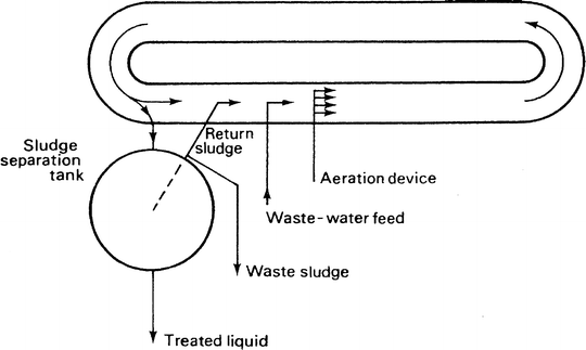
Schematic representation of the Pasveer Ditch activated sludge set-up (From Okafor 2007. With permission)
-
6.
The deep shaft process: The deep shaft system for wastewater treatment was developed by Agricultural Division of Imperial Chemical Industries (ICI) in the UK, from their air-lift fermentor used for the production of single cell protein from methanol. It consists of an outer steel-lined concrete shaft measuring 300 ft or more installed into the ground. Wastewater, and sludge re-cycle are injected down an inner steel tube. Compressed air is injected at a position along the center shaft deep enough to ensure that the hydrostatic weight of the water above the point of injection is high enough to force air bubbles downward and prevent them coming upward. The air dissolves lower down the shaft providing oxygen for the aerobic breakdown of the wastes. The water rises in the outer section of the shaft (Fig. 10.7). The system has the advantage of great rapidity in reducing the BOD and about 50% reduction in the sludge. Space is also saved.
Fig. 10.7 
The deep shaft aeration system (From Okafor 2007. With permission)
-
7.
Enclosed tank systems and other compact systems: Since the breakdown of waste in aerobic biological treatment is brought about by aerobic organisms, efficiency is sometimes increased by the use of oxygen or oxygen enriched air. Enclosed tanks, in which the wastewater is completely mixed with the help of agitators, are used for aeration of this type. Sludge from a sedimentation tank is returned to the enclosed tank along with raw water as in the case with other systems. The advantage of the system is the absence, (or greatly reduced) obnoxious smell from the exhaust gases, and increased efficiency of waste stabilization. This system is widely used in industries the world over.
8. Compact activated sludge systems: These do not have a separate sedimentation tank. Instead, sludge separation and aerobic breakdown occur in a single tank. The great advantage of such systems is the economy of space (Fig. 10.8).
Fig. 10.8 
Compact activated sludge system (From Okafor 2007. With permission)


3.1.1.3 Efficiency of Activated Sludge Treatments
The efficiency of any system is usually determined by a reduction in the BOD of the wastewater before and after treatment. Efficiency depends on the amount of aeration, and the contact time between the sludge and the raw wastewater. Thus, in conventional activated sludge plants the contact time is about 10 h, after which 90–95% of the BOD is removed. When the contact time is less (in the high-rate treatment), BOD removal is 60–70% and the sludge produced is more. With longer contact time, say several days, BOD reduction is over 95% and sludge extremely low.
With systems where oxygen is introduced as in the closed tank system, or where there is great oxygen solubility as in the deep shaft system, contact time could be as short as 1 h but with up to 90% BOD reduction along with substantially reduced sludge.
3.1.2 The Trickling Filter
The trickling filter consists of round rocks 1–4 in. diameter arranged in a bed 6–10 ft deep (Fig. 10.9). Sewage is uniformly spread on the bed by a rotating distributor which is powered by an electric motor or driven by hydraulic impulse where a hydraulic head is available. The sewage percolates by gravity over the rocks and through the spaces between the rocks and the effluent is collected in an under-drain. From the under-drain, the liquid is allowed to settle in a sedimentation tank which is an integral part of the system.

Section through trickling filter bed (From Okafor 2007. With permission)
The sludge consisting of microorganisms and undecomposed matter is removed from time to time and may be used as manure. Various modifications may be made to this basic design. In one modification (see Fig. 10.10), the sewage may be pre-sedimented before filtration; in another, two filters may operate; and in yet others, the effluent may be re-cycled.

Scheme illustrating two arrangements of trickling filter: conventional and single stage (From Okafor 2007. With permission)
Trickling filters may be low-rate or high-rate. Low rate filters handle 2–4 million gallons per acre per day (mgad). They are very efficient in BOD reduction and may attain 85–90% BOD. The effluent is usually still rich in oxygen; hence, nitrates are produced in abundance by nitrifying bacteria. High rate filters handle 10–40 mgad and BOD reduction is only 65–75%. The effluent is usually low in nitrates since much of the O2 is used in breaking down the organic matter load.
3.1.2.1 Microbiology of the Trickling Filter
As the sewage percolates over the stones, micro-organisms break down the organic matter in it. Although the process is described as aerobic, most of the bacteria are in fact facultative. Aerobic conditions operate mainly when the filter is fresh and in the outer areas of the coating of micro-organisms on the rocks in mature filters (see Fig. 10.11). The innermost portion of the coating of micro-organisms may in fact be anaerobic. Bacteria are the most important organisms in the trickling filter, but other organisms are also present.

Oxygen and food zones in the slime coating of rocks in the trickling filter (From Okafor 2007. With permission)
Fungi, for instance, are to be found in the aerobic zone. The fungi, encountered include mainly Fusarium and Geotrichum. Others are Trichosporon, Sepedonium, Saccharomyces and Ascoidea. Fungi are more common in low pH sewages and in some industrial sewages.
Protozoa are present: the flagellates, free-swimming ciliates and, to some extent, amoeba at the upper part of the filter rocks, and the stalked ciliates in the bottom portion. It has been suggested that this stratification is a result of the availability of soluble food at the various levels, the greater portion of such food being available in the surface region. Some protozoa encountered in the surface region are Trepomonas agilis and Vorticella microstoma; in the middle region, Paramecium candatum and Opercularia; and in the innermost layer, Arcella vulgaris and Aspidica costata.
Algae, because of their need for sunlight, are found In the upper layers of the filter and may clog the filter (see Fig. 10.12). The only groups of algae found in both trickling filters and oxidation ponds (see below) are Chlorophyceae, Euglenaphyceae, Cyanophyceae and Chrysophyceae. In the outer portions of the filter, particularly in older filters, algae are to be found throughout the coating of the rocks especially in the middle layer as shown in Fig. 10.1. The algae involved include the unicellular Chlorella, Phormidium, Oscillatoria or the sheet-forming multicellular Stigeoclonium and Ulothrix. Algal photosynthesis provides only some of the oxygen required by the aerobic bacteria which contribute to the breakdown of organic matter. Worms, snails, and larvae are also to be encountered, but these contribute little to the process of filtration.

Diagrammatic transverse section of the slime layers in mature trickling filter (From Okafor 2007. With permission)
The micro-organisms adhere to the rock by weak (van der Waals) forces and grow in one direction only as liquid flows over the film of microbial coating. As the microbial layer increases in thickness, the innermost organisms die and the microbial layer drops off from the rock. A new growth starts thereafter. Since the breakdown is brought about by aerobes, a filter is most efficient when the microbial layer is thinnest or when the filter stones regularly shed their slime coatings.
3.1.3 Rotating Discs
Also known as rotating biological contactors, these consist of closely packed discs about 10 ft in diameter and 1 in. apart. Discs made of plastic or metal may number up to 50 or more and are mounted on a horizontal shaft which rotates slowly, at a rate of about 0.5–15 revolutions/min. During the rotation, 40–50% of the area of the discs is immersed in liquid at a time. A slime of micro-organisms, which decompose the wastes in the water, builds up on the discs. When the slime is too heavy, it sloughs off and is separated from the liquid in a clarifier. It has a short contact time and produces little sludge (Fig. 10.13).

Structure of rotating discs (rotating biological contactor) (From Okafor 2007. With permission)
3.1.4 Oxidation Ponds
Oxidation ponds (also called or Stabilization Ponds) are shallow lagoons about three feet deep into which sewage is discharged at a single point, usually at the center but also occasionally at the side. After suitable periods of holding, the effluent which usually has a low BOD is discharged at a single point. The effluent is usually low in coliforms and may be discharged into a river or used as raw water source. Oxidation ponds are especially appropriate in warm, sunny climates.
Oxidation Ponds are a common sewage treatment method for small communities because of their low construction and operating costs. Oxidation ponds represent 12% of all sewage treatment plants in the US. New oxidation ponds can treat sewage fairly efficiently but require maintenance and periodic de-sludging in order to maintain this standard.
They may be made of one or up to four shallow ponds in series. The natural processes of algal and bacteria growth exist in a mutually dependent relationship.
Oxygen is supplied from natural surface aeration and by algal photosynthesis. Bacteria present in the wastewater use the oxygen and feed on organic material, breaking it down into nutrients and carbon dioxide. These are in turn used by the algae. Other microbes in the pond such as protozoa remove additional organic and nutrients to polish the effluent.
There are normally at least two ponds constructed. The first pond reduces the organic material using aerobic digestion, while the second pond polishes the effluent and reduces the pathogens present in sewage. Sewage enters a large pond after passing through a settling and screening chamber. After retention for several days, the flow is often passed into a second pond for further treatment before it is discharged into a drain. Bacteria already present in sewage acts to break down organic matter using oxygen from the surface of the pond. Oxidation ponds need to be de-sludged periodically in order to work effectively.
Oxidation ponds require large amounts of land and the degree of treatment is weather dependent. The only operation necessary, if at all, is to alter by appropriate valves, the point of the discharge of the raw sewage.
A number of problems may however be associated with oxidation ponds. First, they permit the growth of mosquitoes in countries where malaria and other mosquito-borne diseases abound. The mosquito larvae can be controlled by spraying the ponds with oil. Second, aquatic weeds may clog them but if they are up to 3 ft deep weeds do not grow except at the edges. Depending upon the design. oxidation ponds must be freed of sludge approximately every 10 years. They are sometimes used for the primary stabilization of wastes from dairies; often, however, they are employed as secondary or tertiary treatment facilities.
Oxidation ponds (Gerhardt and Oswald 1990) are usually employed as secondary or tertiary treatment. Occasionally, they are used as primary treatment plants in which case anaerobic conditions tend to occur because of the heavy load. This anaerobic condition is particularly apt to occur in the dark when, as is seen later, the photosynthetic organisms largely responsible for the provision of oxygen to the aerobic bacteria, are inactive.
Oxidation ponds are most often used as secondary treatment for wastewaters or for waters such as shed wastes which contain heavy loads of organic matter. Oxidation pond systems may be a two-pond system (see Fig. 10.14) or a multi-pond one (see Fig. 10.15). Multi-pond systems are usually described as an Advanced Integrated Pond System (AIPS), in which different ponds fulfill different functions. It consists of a series of ponds in the ground, which use heterotrophic bacteria and algae to treat the wastewater. Wastewater first passes into deep pits in the Advanced Facultative Pond. Here, solids are broken down by fermentation anaerobically in a fermentation pit to produce methane and achieve the removal of many pathogens. The water then passes into a High Rate Pond (HRP) for rapid growth of algae and concomitant production of oxygen; in this pond, organic materials are oxidized. In some systems, paddlewheels which revolve slowly help to increase aeration in the HRP. Small ponds immediately down stream remove algae. The water next passes into Maturation Pond where it is held for a period before being discharged. Maturation tanks provide opportunities for pathogen reduction, and when the aim is to reduce pathogens the water may be passed through a series of maturation tponds.

Setup in a two-pond oxidation pond system (Not drawn to scale) (Modified from Gerhardt and Oswald 1990)

Setup in a multiple pond system (Advanced Integrated pond System, AIPS; not drawn to scale) (Modified from Gerhardt and Oswald 1990)
Effluent from AIPS is typically suitable for aquaculture because the fish feed on the algae in it. Under such conditions, the algal settling and maturation ponds may be eliminated or the water may held for shorter periods in them.
The side view of the AIPS (Fig. 10.15) shows that the deepest portion is the fermentation pit where anaerobic breakdown takes place; the HRP is the shallowest being less than a meter deep, so as to encourage aeration.
3.1.4.1 The Microbiology of the Oxidation Pond
The bulk of the stabilization in an oxidation pond is brought about by aerobic bacteria, but zones of growth by anaerobic and facultative bacteria may also exist depending on the depth of the pond. Oxygen is supplied to the aerobic bacteria by two means: (a) Oxygen released by algae during photosynthesis, and (b) Diffusion of oxygen into the water assisted by natural winds and sometimes by floating turbine aerators.
In large oxidation ponds with retention periods of 3 weeks to 3 months, algal aeration by photosynthesis is not very effective; but in smaller ponds with retention time of less than a week, algal photosynthetic oxygen effectively supplies the oxygen required by the aerobic bacteria. Turbine aerators which float on the ponds are often used in large oxidation ponds to encourage O2 diffusion into the pond. The CO2 released by the aerobes is used by the algae (see Figs. 10.15 and 10.16).

Scheme depicting the microbiological activity in an oxidation pond (From Okafor 2007. With permission)
Bacteria, protozoa, algae, and rotifers are all to be found in the oxidation pond. The predominant bacteria are Pseudomonas, Flavobacterium and Alcaligines, but this depends to some extent on the nature of the sewage. Coliforms die off rapidly because they cannot compete for food and because of the predatory activity of ciliates. Some authors suggest that antibiotics released by algae are effective in killing off bacteria.
The algae commonly involved include Chlorella, Spirogyra, Vaucheria and Ulothrix. Some algae are confined to the surface, e.g., Oscillatoria while others are benthic, e.g. Scendemus.
Some of the free-swimming ciliates include Paramecium and Colpidium whereas the stalked ciliates include Vorticella.
In some oxidation pond designs, only one pond is used, especially when it is used for treating effluents from other treatments such as activated sludge or the Imhoff tank (see below). When however it is used on its own, say in dairy or abattoir wastes where the organic matter content is high, at least two ponds are involved. The first is usually deep, and decomposition in it is usually anaerobic. The subsequent ponds are usually aerobic and involve algae (see Fig. 10.15).
3.2 Anaerobic Sewage Systems
3.2.1 Treatment of the Sludge from Aerobic Sewage Treatment Systems: Anaerobic Breakdown of Sludge
As has been seen above, sludge always accompanies the aerobic breakdown of wastes in water. Its disposal is a major problem of waste treatment. Sludge consists of micro-organisms and those materials which are not readily degradable particularly cellulose. The solids in sludge form only a small percentage by weight and generally do not exceed 5% (Fig. 10.17).

Anaerobic digester (From Okafor 2007. With permission)
The goals of sludge treatment are to stabilize the sludge and reduce odors, remove some of the water and reduce volume, decompose some of the organic matter and reduce volume, kill disease causing organisms, and disinfect the sludge. Untreated sludges are about 97% water. Settling the sludge and decanting off the separated liquid removes some of the water and reduces the sludge volume. Settling can result in a sludge with about 96–92% water. More water can be removed from sludge by using sand drying beds, vacuum filters, filter presses, and centrifuges resulting in sludges with between 80% and 50% water. This dried sludge is called a sludge cake. Anaerobic digestion is used to decompose organic matter to reduce volume. Digestion also stabilizes the sludge to reduce odors. Caustic chemicals can be added to sludge or it may be heat treated to kill disease-causing organisms. Following treatment, liquid and cake sludges are usually spread on fields, returning organic matter and nutrients to the soil.
The most common method of treating sludge, however, is by anaerobic digestion and this will be discussed below.
Anaerobic digestion consists of allowing the sludge to decompose in digesters under controlled conditions for several weeks. Digesters themselves are closed tanks with provision for mild agitation, and the introduction of sludge and release of gases. About 50% of the organic matter is broken down to gas, mostly methane. Amino acids, sugars alcohols are also produced. The broken-down sludge may then be de-watered and disposed of by any of the methods described above. Sludge so treated is less offensive and consequently easier to handle. Organisms responsible for sludge breakdown are sensitive to pH values outside 7–8, heavy metals, and detergents and these should not be introduced into digesters. Methane gas is also produced and this may sometimes be collected and used as a source of energy. Figure 10.17 shows the various processes to which sludge may be subjected and some anaerobic sludge digester designs.
3.2.2 The Septic Tank
Septic tanks are small scale sewage systems not connected to main sewage systems. About 26% use this system in North America. Both in North America and in Europe, they are limited to the rural areas. In many parts of the developing world, however, they are the main method of disposing of domestic sewage (Fig. 10.18).

Vertical section of a septic tank (Credit: US Environmental Protection Agency, USEPA; Anonymous 2005b)
A septic tank generally consists of a tank of between 1,000 and 1,500 gal (4,000–5,500 l) which is connected to an inlet wastewater pipe at one end and to a septic drain field or soak away or soakage pit at the other. These pipe connections are generally made via T pipes which allow liquid entry and outflow without disturbing any crust on the surface; i.e., direct current between the inlet and outlet is prevented using baffles and pipe tees.
In the US, the size of the septic tank to be constructed depends on the local authority approving the construction of the residence. Ultimately, it is based on the number of persons expected to use the building. In practice, some authorities base it on the expected flow of wastewater per day, while others base it on the number of rooms Table 10.1 shows tank sizes and the number of persons they should serve.
Wastewater enters through the inlet pipe and the baffle directs it to the bottom. The heavier materials remain at the bottom where they are broken down by anaerobic bacteria, thereby reducing the volume of solids. The oils and fats are not usually broken down as easily as the other materials and they float to the top of scum. As new sewage is added, the accompanying added liquid displaces the top portion of the liquid in the tank into the pipe leading to the soakage pit, taking with it dissolved broken down materials.
Anaerobic decomposition is not as efficient as aerobic and the unbroken down materials form sludge which must be removed from time to time along with the fat scum. Septic tanks have some problems which are the result of the added sewage and its breakdown products remaining in the tank (as opposed to sewers which move the added sewage to the processing location). Thus, excessive addition of fats and oils or flushing down non-biodegradable materials such as sanitary towels may lead to early filling up of the tank. Similarly, the addition of chemicals, such as acid or sodium hydroxide, which can kill off the microorganisms carrying out the decomposition, may also lead to an early filling up of the tank. Roots from trees growing nearby may rupture the tank and shrubbery growing above the tank, or the drain field may clog and or rupture them.
3.2.3 The Imhoff Tank
This is named after its inventor, the German Karl Imhoff. It is widely used. It has an upper flow or sedimentation chamber through which the sewage passes at low velocity, and a lower or digestion chamber into which the heavier sewage particles sediment and are broken down. Methane, which is produced by anaerobic breakdown, is discharged through a pipe and may be collected for use as fuel, while the scum (see Fig. 10.19) and the undigested sediment are transferred from the sedimentation tank by mechanical means to drying beds. The dried sludge is then used as manure.

Diagrammatic cross-section through an Imhoff tank. (From Okafor 2007. With permission)
The effluent from the tanks may be further treated either with a trickling filter or in an oxidation pond. Unpleasant odors which accompany black foams sometimes appear at the gas vents but the odors may be reduced some-what by introducing lime into the vent. Animal manure (i.e., dung and trash) which may also help in odor reduction is added to the gas vents.
The Imhoff tank has no mechanical parts and is relatively easy and economical to operate. It provides sedimentation and sludge digestion in one unit and when operating properly, produces a satisfactory primary effluent with a suspended solids removal of 40–60% and a BOD reduction of 15–35%. The two- storey design requires a deep over-all tank. The Imhoff tanks is best suited to small municipalities and large institutions where the population is 5,000 or less, and a greater degree of treatment is not needed.
3.2.4 Cesspools
Cesspools are shallow disposal systems that are generally constructed as a concrete cylinder with an open bottom and/or perforated sides (drywell). They are used by multi-family residential units, churches, schools, and public meeting facilities, office buildings, industrial and commercial buildings, shopping malls, hotels and restaurants, highway rest stops, state parks, and camp grounds (Fig. 10.20).

Diagram of a cesspool (From http://www.epa.gov/region9/water/groundwater/uic-hicesspools.html; Anonymous 2010a. With permission)
This untreated sanitary waste can enter shallow groundwater and contaminate drinking water resources because they are designed to isolate but not to treat sanitary waste. They may introduce into ground water the following undesirable items: Nitrates, total suspended solids, and coliform bacteria exceeding the quantities recommended for drinking water, as well as other constituents of concern such as phosphates, chlorides, grease, viruses, and chemicals used to clean cesspools (e.g., trichloroethane and methylene chloride). On account of this, the EPA has from 2,000 banned new large-capacity cesspools and existing ones must be closed by 2005.
The EPA defines a cesspool as typically a “drywell” which sometimes has an open bottom and/or perforated sides, and receives untreated sanitary waste. The EPA considers a cesspool large capacity when used by
-
(a)
Multiple dwelling, community, or regional system for the injection of waste (e.g., a townhouse complex or apartment building), or
-
(b)
Any nonresidential cesspool that is used solely for the disposal of sanitary waste and has the capacity to serve 20 or more people per day (e.g., a rest stop or church)
Breakdown of organic matter is anaerobic as no aeration is introduced. The cesspool resembles a septic tank in which the broken down materials seep into the ground without going through a T-pipe.
4 Advanced Wastewater Treatment
Ordinarily, effluents from waste treatment plants such as the activated sludge or the Imhoff systems are discharged into rivers or streams. Such water is sometimes insufficiently treated to provide reusable water for industrial and/or domestic recycle; in addition, it may cause an excessive increase in nutrients such as nitrogen and phosphorus leading to eutrophication. Thus, additional treatment steps have been added to wastewater treatment plants to provide for further organic and solids removals or to provide for removal of nutrients and/or toxic materials. The need for the further treatment of effluents from conventional or secondary treatments has been accentuated by the interest in the control of environmental pollution. This further treatment of effluents is known as Advanced Wastewater Treatment (AWT) or tertiary wastewater treatment. The EPA defines AWT as “any treatment of sewage that goes beyond the secondary or biological water treatment stage, and includes the removal of nutrients such as phosphorus and nitrogen, and a high percentage of suspended solids.”
Apart from the possibility of drinking, water resulting from AWT can be used for the following: recreational water, e.g. in swimming pools; irrigation in agricultural practice; industrial processes such as cooling, and in replenishing underground water.
Several components appear to be included in the term AWT, and what is included varies from one locality to another.
Some constituents of effluents which may give rise to concern are:
-
1.
Inorganics – metals, nitrate, phosphorous, and total dissolved solids (TDS)
-
2.
Organics – trace organics, pesticides, color
-
3.
Micro-organisms – viruses, bacteria
-
4.
Physical – suspended solids, turbidity
4.1 Methods Used in Advanced Wastewater Treatment
Some methods used in AWT are discussed below. They are usually expensive and in the USA, are usually used for purified bottled water and for specialized uses. Where AWT methods are adopted for municipal large-scale treatment, the users usually agree to pay more for the product. The AWT methods to be discussed are: (1) Reverse osmosis, nanofiltration, ultrafiltration and microfiltration; (2) Electrodialysis; (3) Activated charcoal; (4) Ion exchange; (5) UV oxidation; and (6) Precipitation.
-
1.
Reverse Osmosis, Nanofiltration, Ultrafiltration and Microfiltration
In reverse osmosis, wastewater is forced through cellulose acetate membranes at high pressure (about 500 lb/in.2). Salts and organic materials are rejected by the membrane, but water is allowed to pass. This is the reverse of the normal osmosis process, which is the natural movement of solvent from an area of low solute concentration, through a membrane, to an area of high solute concentration when no external pressure is applied. The membrane here is semipermeable, and allows the passage of solvent but not of solute. Ordinary osmosis is the diffusion of a solvent through a selective membrane from a solution of higher solvent concentration to one of lower concentration. However, in reverse osmosis, because of the higher pressure applied, solvent will flow from the solution that is lower in concentration to that which is higher. The rejected organic macro-molecules tend to block the membrane and have to be removed. This process requires that a high pressure be applied on the high concentration side of the membrane, usually 2–17 bar (30–250 psi) for fresh and brackish water, and 40–70 bar (600–1,000 psi) for seawater, which has around 24 bar (350 psi) natural osmotic pressure which must be overcome. This process is best known for its use in the desalination of sea water to fresh water, but it has also been used to produce water for medical and industrial applications.
Nanofiltration is very similar to reverse osmosis. The key difference is the degree of removal of monovalent ions such as chlorides. Reverse osmosis removes the monovalent ions at 98–99% level at 200 psi. Nanofiltration membranes’ removal of monovalent ions is slightly less, and varies between 50% and 90% depending on the material and manufacture of the membrane (Fig. 10.21).
Fig. 10.21 
Comparison of the capabilities of different filtration methods (Modified from Pinnau 2008)
Both methods are applied in drinking water purification process steps, such as water softening, decoloring, and micro pollutant removal such as coloring agents. Nanofiltration is a pressure related process, during which separation takes place, based on molecule size. Membranes bring about the separation. The technique is mainly applied for the removal of organic substances, such as micro pollutants and multivalent ions. In water treatment, specifically they are used for the removal of pesticides from groundwater, the removal of heavy metals from wastewater, wastewater recycling in laundries, water softening, and nitrates removal.
In ultrafiltration the membrane functions as a molecular sieve. It separates dissolved molecules on the basis of size by passing a solution through a very fine filter. The ultrafilter is a thin, selectively permeable membrane that retains most macromolecules above a certain size including colloids, microorganisms, and pyrogens (fever-causing compounds, mainly derived from the cell walls of Gram-negative bacteria). Smaller molecules, such as solvents and ionized contaminants, are allowed to pass into the filtrate. Thus the ultrafilter retains a fraction that is rich in large molecules and a filtrate that contains few, if any, of these molecules.
Ultrafiltration removes most particles including pyrogens, microorganisms, and colloids above their rated size, and produces the highest quality water for the least amount of energy. It is also regenerable. However, it will not remove dissolved inorganics.
Microfiltration will not remove dissolved inorganics, chemicals, pyrogens or all colloidals; it is not regenerable and it is expensive. However, it requires minimal maintenance and removes all particles and microorganisms greater than the pore size (Anonymous (2007a).
-
2.
Electrodialysis
Electrodialysis is a membrane process, during which ions are transported through semi permeable membrane, under the influence of an electric potential (Anonymous 2005a). The membranes are arranged in a stack and are cation- or anion-selective, and thus either positive ions or negative ions will flow through. Cation-selective membranes are polyelectrolytes with negatively charged matter, which rejects negatively charged ions and allows positively charged ions to flow through. By placing multiple membranes in a row, which alternately allow positively or negatively charged ions to flow through, the ions can be removed from wastewater. The membranes are separated from each other in the stack by non-conductive spacers (see Fig. 10.22).
Fig. 10.22 
Diagram illustrating the principle of electrodialysis (Modified from (Anonymous 2005a)
In some columns, concentration of ions will take place and in other columns ions will be removed. The concentrated saltwater flow is circulated until it has reached a value that enables precipitation. At this point, the flow is discharged. This technique can be applied to remove ions from water. Particles that do not carry an electrical charge are not removed. Cation-selective membranes consist of sulfonated polystyrene, while anion-selective membranes consist of polystyrene with quaternary ammonia.
Sometimes pre-treatment is necessary before the electro dialysis can take place. Suspended solids with a diameter that exceeds 10 μm need to be removed, or else they will plug the membrane pores. There are also substances that are able to neutralize a membrane, such as large organic anions, colloids, iron oxides, and manganese oxide. These disturb the selective effect of the membrane. Pre-treatment methods, which aid the prevention of these effects, are active carbon filtration (for organic matter), flocculation (for colloids), and filtration techniques.
Electrodialysis is cost competitive compared to reverse osmosis when producing drinkable water, but it has a number of shortcomings for the production of water of higher purity than drinking, say for laboratory or medical work. Electrodialysis does not remove organics, pyrogens (materials which give fever in injection water, e.g., walls of Gram negative bacteria) and metallic elements which have weak or nonexistent surface charges because they are attached to the membranes. Some colloids and detergents, can plug the membranes’ pores reducing their ionic transport ability, and requiring frequent cleaning. Furthermore, electrodialysis releases hydrogen gas which is potentially explosive. It is relatively expensive to build because it uses expensive materials such as stainless steel and platinum, and its operation is equally expensive because of the high amount of electricity it consumes. Finally, the system requires a skilled operator and routine maintenance. Electrodialysis is used to desalt sea water, brackish ground water and water from estuaries, or river mouths.
-
3.
Activated Charcoal
Activated charcoal or activated carbon, is a material with an exceptionally high surface area. Just 1 g of activated carbon has a surface area of approximately 500 m2, determined by nitrogen gas adsorption. It has a wide range of applications including gas purification, metal extraction, water purification, medicine, sewage treatment, air filters in gas masks and filter masks, filters in compressed air, and many other applications.
It is used in homes to remove taste and odor from drinking water, as well as organic compounds such as volatile organic compounds, pesticides, benzene, some metals, chlorine, and radon. It must be changed regularly; bacteria may grow in it using the organic materials accumulated on the filter.
-
4.
Ion exchange
Ion exchange resins are insoluble matrix or support structure normally in the form of small (1–2 mm diameter) beads, colored white or yellowish, made from an organic polymer material. A matrix of pores on the surface of the beads easily trap and release ions. The trapping of ions takes place only with simultaneous releasing of other ions, and hence the process is called ion exchange. Different types of ion exchange resin are fabricated to selectively prefer one or several different types of ions.
Ion exchange resins are widely used in different separation, purification, and decontamination processes. Most common, they are used for water softening and water purification. Before the introduction of resins, zeolites, which are natural or artificial alumino-silicate minerals, which can accommodate a wide variety of cations, such as Na+, K+, Ca2+, Mg2+, were used.
For water softening, ion-exchange resins are used to replace the magnesium and calcium ions found in hard water with sodium ions. When in contact with a solution containing magnesium and calcium ions, but a low concentration of sodium ions, the magnesium and calcium ions preferentially migrate out of solution to the active sites on the resin, being replaced in solution by sodium ions. This process reaches equilibrium with a much lower concentration of magnesium and calcium ions in solution than was started with.
The resin can be recharged by washing it with a solution containing a high concentration of sodium ions (e.g., it has large amounts of common salt (NaCl) dissolved in it. The calcium and magnesium ions migrate off the resin, being replaced by sodium ions from the solution until a new equilibrium is reached. This is the method of operation used in dishwashers that require the use of “dishwasher salt.” The salt is used to recharge an ion exchange resin which itself is used to soften the water so that limescale deposits are not left on the cooking and eating utensils being washed.
For water purification, ion exchange resins are used to remove undesirable constituents e.g., copper and lead ions from solution, replacing them with more innocuous ions, such as sodium and potassium.
-
5.
UV Oxidation
Ultraviolet (UV) oxidation is an important purification technology used in the production of high-purity water for the chemical, food and beverage, pharmaceutical and semiconductor industries and also for laboratory work. When combined with other purification technologies in a complete water system, UV oxidation provides unique benefits in the reduction of dissolved organics and microorganisms. In order to oxidize organics and reduce TOC in purified water, a UV lamp which emits both UV185 and UV254 must be used. UV185 not only breaks organic bonds, but also generates free radicals, which are short-lived, highly reactive molecules or atoms which can rapidly oxidize many organic and some inorganic molecules, including one of the most powerful oxidizing species, the hydroxyl radical (OH•). The OH• created may freely react with organic molecules to partially ionize or fully oxidize them to CO2 and water.
The hardware used to generate UV radiation in a water purification system includes a low-pressure, mercury vapor lamp, a ballast, and a power supply (see Fig. 10.23). The lamp consists of a sealed quartz tube with electrodes (cathodes) on each end. The lamp tube contains a small amount of mercury and an inert gas, such as argon or neon, at a very low pressure. The power supply energizes the ballast which regulates the current to the lamp. Electrical current from the ballast pre-heats the lamp cathodes.
Fig. 10.23 
Schematic diagram of a generalized apparatus for sterilizing water with UV light (Modified from http://www.oceanreeflections.com/uv_school.htm; Anonymous 2010b)
-
6.
Precipitation
The following treatment methods have been approved by the USEPA for removing nitrates/nitrites: Ion exchange, Reverse Osmosis, Electrodialysis. However precipitation is the main method for the removal of phosphorous in effluents of wastewater treatment.
Mineral addition and lime addition are the principal methods for in-plant removal of phosphorus from wastewater. The most commonly used of these metal salts are: Alum, a hydrated aluminum sulfate (Al2SO3).18 H2O); sodium aluminate (Na2O.Al2O3); ferric sulfate (Fe2(SO4)3); ferrous sulfate (FeSO4); ferric chloride (FeCl3); and ferrous chloride (FeCl2). Mineral addition is usually followed by anionic polymer addition, which aids flocculation; the pH may require adjustment depending on the particular process. In lime addition, phosphorus removal is attained through the chemical precipitation of hydroxyapatite, Ca5OH (PO4)3.


References*
Andrew, W. (1996). Biotechnology for waste and wastewater treatment. Westwood: Noyes.
Anonymous. (2004). Local limits development guidance (EPA 833-R-04-002A). Washington, DC: Office of Wastewater Management, USEPA.
Anonymous. (2005a). Electrodialysis: A method to deionize water and to recover the salt. http://www.pca-gmbh.com/appli/ed.htm. Accessed 25 July 2010.
Anonymous. (2005b). A homeowner’s guide to septic systems (EPA-832-B-02-005). Washington, DC: United States Environmental Protection Agency.
Anonymous. (2006). Standard methods for the examination of water and wastewater. Washington, DC: American Public Health Association, American Water Works Association, Water Environment Federation.
Anonymous. (2007). Different water filtration methods explained. http://www.freedrinkingwater.com/water-education/quality-water-filtration-method.htm. Accessed 28 Aug 2007.
Anonymous. (2010a). Underground Injection Control (UIC). http://www.epa.gov/region9/water/groundwater/uic-hicesspools.html. Accessed 10 Sept 2010.
Anonymous. (2010b). More UV sterilizer info. http://www.oceanreeflections.com/uv_school.htm. Accessed 12 Sept 2010.
Curds, C. (1965). An Ecological Study of the Ciliated Protozoa in Activated Sludge. Oikos, 15, 282–289.
Eckenfelder, W. W. (2000). Industrial water pollution control. Boston: McGraw-Hill.
El-Rehaili, A. M. (1994). Implications of activated sludge kinetics based on total or soluble BOD, COD and TOC. Environmental Technology, 15, 1161–1172.
Gerhardt, M.B., & Oswald, W.J. (1990). Advanced ingrated ponding system in sewage reuse. In P. Edwards, & R.S.V. Pullin (Eds.), Wastewater-fed aquaculture. Proceedings of the international seminar on wastewater reclamation and re-use for aquaculture, Calcutta, India, 6–9 December, 1988. Bangkok, Thailand: Environmental Sanitation Information Centre, Asian Institute of Technology.
Kosric, N., & Blaszczyk, R. (1992). Industrial effluent processing. In Encyclopedia of microbiology (Vol. 2, pp. 473–491). San Diego: Academic.
Lindera, K. C. (2002). Activated sludge – the process. In Encyclopedia of environmental microbiology (Vol. 1, pp. 74–81). New York: Wiley-Interscience.
Nielsen, P. H. (2002). Activated sludge – the floc. In Encyclopedia of environmental microbiology (Vol. 1, pp. 54–61). New York: Wiley-Interscience.
Okafor, N. (2007). Modern industrial microbiology and biotechnology. Enfield: Science Publishers.
Pinnau, I. (2008). Membranes for water treatment: Properties and characterization. http://www.stanford.edu/group/ees/rows/presentations/Pinnau.pdf. Accessed 21 Aug 2010.
Young, J. C., & Baumann, E. R. (1976). The electrolytic respirometer – I factors affecting oxygen uptake measurements. Water Research, 10, 1031–1040.
Author information
Authors and Affiliations
Corresponding author
Rights and permissions
Copyright information
© 2011 Springer Science+Business Media B.V.
About this chapter
Cite this chapter
Okafor, N. (2011). Waste Disposal in the Aqueous Medium: Sewage Disposal. In: Environmental Microbiology of Aquatic and Waste Systems. Springer, Dordrecht. https://doi.org/10.1007/978-94-007-1460-1_10
Download citation
DOI: https://doi.org/10.1007/978-94-007-1460-1_10
Published:
Publisher Name: Springer, Dordrecht
Print ISBN: 978-94-007-1459-5
Online ISBN: 978-94-007-1460-1
eBook Packages: Earth and Environmental ScienceEarth and Environmental Science (R0)