
Abstract
In recent years, semiconductor lighting technology, also known as green lighting, has been developed rapidly. The light-emitting diode (LED) is one of the most promising solid green light sources of the twenty-first century.
Access provided by CONRICYT-eBooks. Download chapter PDF
In recent years, semiconductor lighting technology, also known as green lighting, has been developed rapidly. The light-emitting diode (LED) is one of the most promising solid green light sources of the twenty-first century. LED communication offers an entirely new paradigm within wireless technology in terms of communication speed, flexibility, usability, and security. Right now, a great opportunity is available to us by using the current state-of-the-art LED lighting solutions for illumination and communication simultaneously, as well as with the same modulation. This can be done due to the ability that we can modulate LEDs at speeds far faster than the human eye can detect, while still providing artificial lighting. Thus, while LEDs will be primarily used for illumination, their secondary duty could be data communication through a lighting system. Visible light communication (VLC) technology, with visible light as the carrier, is a new type of wireless optical communication technology based on the LED light system. In this chapter, we will introduce the different kinds of LED, their driven design, their lighting light field, and their visual design.
2.1 Summary of the LED
2.1.1 The Development of the LED Light Source
Light-emitting diodes were discovered early in the twentieth century. Even as early as 1907, the luminescence phenomenon, produced by the PN junction of silicon carbide (SiC), was discovered. In the late 1920s and early 1930s, another discovery was made, which was that yellow phosphor derived from zinc sulfide and copper also emitted light. However, one after the other, people have stopped researching this science because the light produced by SiC and yellow phosphor is very dark. Nevertheless, the early research left an everlasting impression of electroluminescence on people. In 1962, Dr. Nick Holonyak invented the red LED with semiconductor compound materials of red phosphor gallium arsenide (GaAsP), which was developed by a joint laboratory effort including General Electric (GE), Monsanto, and International Business Machines (IBM). This LED was used as an indicator, until the luminescence efficiency of red LED decreased to 0.1 lm/W in 1965. In 1968, people made the luminescence efficiency of the GaAsP LED improve significantly, up to 1 lm/W, through a doping process. Furthermore, they also fabricated the first orange and yellow LEDs. The industry generally suggests that the red LED, which has real commercial value, appeared in the late 1960s.
From 1970 to 1971, the green LED, whose luminescence efficiency corresponded to that of the red LED, gradually appeared. Now entering into the mid-1970s, the gallium phosphide (GaP) green LED was born. Before entering the 1980s, LED colors were primarily limited to just three colors, red, yellow, and green. The luminous intensity of LEDs remained at the level of 1 mcd, and the luminescence efficiency was around 1 lm/W. LED lamps were mainly used as indicator lamps for the electronic products in this period. After entering the 1980s, researchers tried to use aluminum gallium arsenic (AlGaAs) to improve the LED’s performance, and thus, the green and orange LEDs were fabricated. This resulted in an increase in the luminescence efficiency of red LEDs by nearly ten times. Because of the improvement of the LEDs’ luminescence efficiency, LEDs were then applied to many more areas, such as outdoor display systems, bar code systems, photoelectric conduction systems and medical equipment.
On another note, the idea of a white light-emitting diode (LED) is not inherently unusual or surprising. It was not until the recent successful creation of high-frequency blue/violet light LEDs that the white LED made its debut. With the attributes of a highly efficient and cold light source, the white LED market will surely have enormous growth. In addition, the white LED will be a promising candidate for the replacement of the light bulb once production costs fall thanks to the future’s technology advances. Nichia Co., who also created the first blue LED, produced the first commercially available white LED that was based on phosphors. Nichia used a blue light-emitting gallium indium nitride and coated the chip with the yellow fluorescent phosphor Y3Al5O12: Ce, well known now as (YAG: Ce). In addition, yellow phosphor Tb3Al5O12: Ce (TAG: Ce) was also used by OSRAM Co. with the GaInN chip for white light production. YAG and TAG, when activated with trivalent cerium, are efficient phosphors for converting the blue LED radiation into a very broad yellow emission band. The yellow emission from YAG: Ce and TAG: Ce is intense enough to complement the residual blue light which escapes through the phosphor in order to produce a white light. By far, YAG: Ce and TAG: Ce are the most excellent phosphors that have been applied successfully in the white phosphor-based LED commercial market. Therefore, any improvement in the luminescence of YAG: Ce and TAG: Ce is extremely valuable to improve the light efficiency of different applications.
The discovery of the white LED has great significance for LEDs as a new generation of an electric light source in the twenty-first century. White LEDs are commonly used as the back light source of mobile phones, PDA, and small LCD displays. The development of white LEDs is changing with each passing day. Similar to the microprocessor, LED development abides by Moore’s law. Its brightness will double every 18 months, and its photosynthetic efficiency will be enhanced at an annual rate of 10–20 lm/W. The development of LEDs also follows Haitz law, which is named after Agilent former scientist Roland Haitz. This law states that the price of a LED will be one-tenth of the original price every 10 years, and its performance will enhance 20-fold. In recent years, the luminous efficiency of LEDs have enhanced unceasingly. Many of the related products’ performances are significantly better than the affordable fluorescent lamp. For example, United States’ Cree, Inc. launched a white LED with a luminous efficiency of 131 lm/W in 2006, and now, the luminous efficiency of white LEDs is already as high as 150 lm/W, thanks to Nichia Corporation. In January 2007, Philips Lumileds Lighting Company, who originally obtained a rate of 115 lm/W, promulgated the luminous efficiency of a high-power white LED. With the development of a fixed power LED, some general lighting products, such as the large-size LCD backlight, miner’s lamps, LED road lighting lamps, and even lanterns, have been constantly emerging. Experts predict that the white light semiconductor lighting will create an output value of 150 billion RMB, and accumulatively save about 400 billion degrees of energy in China from 2005 to 2015.
2.1.2 The LED’s Luminescence Mechanism
Luminescent materials, also called phosphors, are mostly solid inorganic materials consisting of a lattice host and usually intentionally doped with impurities. According to the mechanism of luminescence, an electrical light source used for lighting can be divided into several major categories including thermal radiation light sources, thermal gas discharge light sources, and electroluminescent light sources. Currently, the thermal radiation light source is represented by an incandescent bulb and the thermal gas discharge source is represented by a fluorescent lamp, which are both widely used. Meanwhile, electroluminescence is a type of light source that is currently being further developed. According to the principle of light, electroluminescent lighting can be divided into two categories: intrinsic electroluminescence and injected electroluminescence. For example, the semiconductor light-emitting diode is a type of an injected electroluminescent, which can be considered as a phenomenon that emits the solid material’s light directly under the effect of the electric field.
As the name implies, a semiconductor diode is subject to a small forward-biased voltage, where the electrons are injected into a conduction band that is normally empty. By emitting their energy as photons, the injected electrons are recombined with the holes in the valence band. This process is called electroluminescence or spontaneous emission. Since an optical cavity does not need to provide photon feedback, and the emitted photons have random phases, the LEDs are considered incoherent light sources. Furthermore, the emitted photon energy is close to the band-gap of the semiconductor material. When a PN junction is forward biased, both electrons from the N-region and holes from the P-region are injected into the main active region. When free electrons and free holes coexist with comparable momentum, they will combine and possibly emit photons with energy near the band-gap, resulting in a LED. The process is called injection (or electro-) luminescence, because the injected carriers recombine and emit light through spontaneous emission.
The forward-biased PN junction injects electrons and holes into the GaAs active region. The AlGaAs cladding layers confine the carriers in the active region. A high-speed operation requires high levels of injection (and/or doping) so that the recombination rate of the electrons and holes is very high. This means that the active region should be very thin. However, nonradiating recombination increases at a higher carrier concentration, so there is a trade-off between internal quantum efficiency and speed. Under some conditions, LED performance is improved by using quantum wells or strained layers. For example, a sketch of a LEDs’ PN junction is shown in Fig. 2.1. The light emission is produced by the radiating recombination of electrons injected into the P-type material because the electron current is much larger than the hole current. Electrons are injected when the PN junction is forward biased because the injection efficiency relates the current “useful” carriers, which are the electrons injected in the P-type region, to the remaining carriers that are currently in the junction. The junction is where the electron current is injected into the P-type region, and the hole current is injected in the N-type region. Overall, it represents the current of the carriers that are recombining in a nonradiating way. Usually, it reaches a value of 30–60%.

Principle diagram of semiconductor light-emitting diodes
A LED is a simple PN junction made with semiconductor material that exhibits radiating recombination properties. This PN junction can either be a hetero-junction or a homo-junction. The material of the semiconductor’s energy band-gap determines the frequency of the emitted light, according to the relationship Eg = hv. For PN junction LEDs, the wavelength of the emitted light depends on the band-gap of the material. For narrow band-gap materials, the wavelength is in the infrared region, and for wide band-gap materials, the wavelength is in the visible and ultraviolet spectral regions. In addition to the specific band-gap requirements, the semiconductor material should be easily doped with both N-type and P-type dopants to form the junction. For example, GaAs is a direct semiconductor material and it can be easily doped with donors or acceptors. GaAs-LEDs usually have a wavelength of around 0.855 μm at room temperature. On the other hand, GaN is another direct semiconductor material, but has a band-gap of ∼3.40 eV (0.365 μm). A LEDs’ wavelength can be tuned easily by choosing ternary materials such as AlGaAs, InGaN, and AlGaN.
2.1.3 Characteristics of a LED
-
(1)
Spectral Characteristics
The spectral characteristics of a LED include the emission wavelength, the spectral width, and the spectral shape. The emission wavelength of a direct-gap LED is determined by the band-gap of the active layer. Because the band-filling effect of both the injected electrons and the holes fills the space near the edges of the conduction and valence bands, this causes the emission wavelength peak to be somewhat shorter than λg = hc/Eg and corresponds to a photon energy that is somewhat larger than the band-gap energy. However, if the active layer is heavily doped, the formation of band-tail space can lead to a long emission wavelength, which corresponds to photon energy smaller than the band-gap energy. For an indirect-gap LED doped with isoelectronic impurities, the emission wavelength is longer than λg, with photon energy smaller than the band-gap energy.
The emission wavelength peak of a LED varies depending on the injection current and temperature. Because the band-gap of a III–V semiconductor normally decreases with increasing temperature, a LED’s emission wavelength peak becomes longer as the operating temperature increases. The rate of change depends on the LED’s specific semiconductor material. When the injection current increases, the band-filling effect, which is caused by the increasing concentration of the injected carriers, leads to an increase in the emitted photon energy. This then results in a corresponding reduction to the emission wavelength peak. This effect is often abated by the shrinkage of the band-gap, which is due to the heating of the junction that accompanies the injection current increase.
The spectral width and the shape of the emission are intrinsically defined by the spontaneous emission spectrum. However, a LEDs’ emission spectra is often further complicated by frequency-dependent absorption and then scattered by impurities and other materials. These other materials have different band-gaps and are located in the LED’s layered structure. In terms of the spectral width of the photon energy, it is approximately h∆ν = 3 kBT, but it can range between 2 and 4 kBT. At room temperature, the spectral width of a LED is approximately 80 meV, but it can be as narrow as 50 meV, or as broad as 100 meV, in some devices. In terms of the optical wavelength, the spectral width ∆λ ranges from approximately 20 nm for InGaN-LEDs, which emit short-wavelength ultraviolet or blue light, to the range of 100 nm for InGaAsP-LEDs, which emit long-wavelength infrared emissions. The spectral width of a LED normally increases with both temperature and the injection current. Because a LED emits spontaneous radiation without an optical cavity, the longitudinal and transverse mode structures, which are characteristic of a laser spectrum, do not exist in the LED’s emission spectrum. Figure 2.2 shows a representative emission spectrum of a LED.

Emission spectrum of a LED
The spectral characteristics of a LED reflect its strengths and weaknesses of monochromaticity. Many LEDs cannot produce monochromatic light; that is, to say, there is not only one peak wavelength, so we have introduced the term “dominant wavelength” in order to describe the spectral properties of LEDs. A dominant wavelength is defined as the wavelength of main monochromatic light observed by the human eye. A LED has only one dominant wavelength, although some LEDs can give multiple wavelengths of light.
-
(2)
Light Distribution Characteristics
Adopting different lens encapsulation structures does not only improve the luminous efficiency of LED, but can also obtain certain light distribution features. Figure 2.3 gives the light distribution characteristics of a common LED.

Light distribution characteristics curve of a LED
It is important to note that the LED structure center may not be the optical center. The optical center usually deviates from 5° or more from the structure center. Although there is not much of a problem when measuring with an angle of 40° or more, the deviation should be considered when the view angle is below 40°. Commission International Ed l’eclairage (CIE) recommends that when measuring, it is best to use the structure center rather than the optical center.
-
(3)
Thermal Characteristics
The temperature has a great influence on the light output of a LED. The temperature of the PN junction will increase when a current flows through the LED, and this junction temperature change is bound to cause microscopic parameters to change, such as the concentration of internal electrons and holes, forbidden bandwidth, electron mobility. Therefore, corresponding changes take place in the macro-parameters such as the LED light output, light wavelength, the forward voltage. The relationship between the luminous flux output of a LED and the junction temperature can be expressed as:
where \( F_{V} (t_{J1} ) \) is the luminous flux output when the junction temperature is \( t_{J1} \), \( F_{V} (t_{J2} ) \) is the luminous flux output when the junction temperature is \( t_{J2} \), K is the temperature coefficient associated with luminescent material, and the K-value of AlInGaP and InGaN is about 1 × 10⁻² and 1 × 10⁻³, respectively.
The diminution of forbidden materials along the bandwidth, combined with the LED’s rising junction temperature, will lead to a redshift effect of the LED light wavelength. This relationship can be represented as:
where \( \lambda_{d} (t_{J2} ) \) and \( \lambda_{d} (t_{J1} ) \) are the dominant wavelengths when the junction temperatures are \( t_{J1} \) and \( t_{J2} \), respectively; and \( K_{d} \) is the wavelength coefficient that varies with the temperature, which is directly related to the material.
An increase in the LED junction temperature will cause the diminution of the forward turn-on voltage represented by \( V_{F} \). The relationship can be expressed as:
where \( V_{F} (t_{J1} ) \) and \( V_{F} (t_{J2} ) \) are the forward pressure drops of a LED when the junction temperatures are \( t_{J1} \) and \( t_{J2} \), respectively; and K is the voltage temperature coefficient. The K-value is about −2 mV/°C for main luminescence materials such as AlInGaP and InGaN.
When the junction temperature does not exceed the maximum critical temperature, the forward voltage drop is reversible with temperature change, or else, the LED light output characteristics will be in permanent decline. The highest junction temperature of a LED is related not only to the material, but also to another factors, such as the encapsulation structure. An increase of the LED junction temperature will cause a decrease in the output flux. Once a LED is lit the junction temperature increases along with the consumption of energy, and it only takes a few seconds or minutes for the output to reach thermal equilibrium. Thus, it is necessary to carry out an aging treatment for LEDs before measurement. In addition, with the increase of temperature, the output power of a LED will decrease and a redshift effect will result.
-
(4)
Current–Voltage Characteristics
A LED is a kind of PN junction diode. As we have seen earlier, the static current–voltage characteristics of a PN diode can be described by a simple exponential equation:
where \( I_{S} \) is the reverse saturation current, q is the quantity of electrical charge (q = 1.602 × 10⁻¹⁹ C), n equals 1 or 2, K is the Boltzmann constant (k = 1.38 × 10⁻²³ J/K), and T is the thermodynamic temperature (when the room temperature is 25 °C, T = 273 + 25 = 98 K, \( \frac{q}{KT} \approx 39/{\text{V}},\frac{KT}{q} \approx 26\,{\text{mV}} \)).
Like an ordinary rectifier diode, a LED has characteristics such as unidirectional conductivity and nonlinear properties. Figure 2.4 gives the forward volt–ampere characteristic curve of a high-power LED. A forward voltage applied to a LED can produce a forward current. When the voltage is too small, the LED’s current is also small and the resistance is large, because the external electric field is not enough to overcome the resistance caused by the internal electric field against the carrier diffusion. But when the voltage exceeds a certain value, the internal electric field is greatly weakened and the resistance becomes very small, so the current increases exponentially. Thus, it is necessary that a precise and constant current source be employed during the process of measurement to retain the stability of the LED light source.

Volt–ampere characteristic curve of a high-power LED
-
(5)
Output Characteristics
Inside a LED, the output optical power \( P_{\text{out}} \) is linearly proportional to the drive current, and this relation defines the output efficiency \( \eta \):
This efficiency is strongly affected by the LED’s geometry. The internal quantum efficiency, or ratio of emitted photons to incident electrons, is usually close to 100%. The light emitted versus the current produces some nonlinearities, which are much less than a laser diode, but, nevertheless, causes some nonlinearities in the LED’s modulation. This LED nonlinearity arises from both the material properties and the device’s configuration, and it may be made worse by ohmic heating at high drive currents. The residual nonlinearity is an important characteristic of any LED used in communication systems. Edge emitters are typically less linear because they operate closer to the amplified spontaneous limit.
The performance index of a LED as a light source includes the light and electrical parameters of an electric light source. The electrical parameters consist of the voltage, current, and power. The electrical performance is simple, because the LED is driven by a direct current (DC). However, the current of a LED has no linear relationship with the voltage. Figure 2.5 shows the volt–ampere curve of a LED.

Volt–ampere curve of a LED
Optical parameters include the luminous flux output, spectral energy distribution, chromaticity coordinates and the color-rendering index, light intensity spatial distribution. The spectral bandwidth range of a monochromatic LED is generally from 20 to 35 nm, which is a narrowband spectrum. The output spectrums of white LEDs vary considerably with the mechanisms of production. The output of the LED light space distribution is directly related to the encapsulation structure. The light angle output of the illuminator LED is usually bigger than the display LED. Figure 2.6 shows the epitome of the LED output characteristic curve.

Output performance of a LED based on a the spectral energy distribution of a LED and b the spatial light intensity distribution of a LED
2.1.4 The Types of White LEDs
The color-rendering index is a unit-less index and is abbreviated variously as either CRI or Ra. CRI is a measure of the degree to which the perceived colors of objects, illuminated by the source, conform to those of the same objects that are illuminated by a reference source for specified conditions. According to the basic principle of white light, we can get the white light from the following several ways.
-
(1)
Complementary colors
By definition, two colors are said to be complementary when their combination yields white light. The corresponding numerical relationship and the luminous power ratio between the wavelengths of complementary monochromatic lights, which are based on the CIE 1964 supplementary standard colorimetric observer, are shown in Table 2.1.
-
(2)
Mixing three colors
White light can be received by combining three colors of light with a particular wavelength, when mixed with a certain power ratio.
-
(3)
Full-wavelength radiation
The entire optical wavelength of light is launched through a broadband generator, which closely resembles the solar spectrum.
-
(4)
Combination of the three methods above
The three former methods can be combined to form white light. For example, the broadband generator and single wavelength generator are used to generate white light.
For LEDs, presently there are three main methods to obtain white light. (1) PC-LED: Yellow phosphor is coated on a blue LED and then a part of the blue light is launched passing through the phosphor with the proper design, which is composed of the blue part of the spectra. At the same time, the remaining portion of the blue light is converted into red and green parts of the spectrum by phosphor. (2) RGB-LED: The white light is produced by adjusting the power of the red, green and blue LEDs all together. (3) UV-LED: White light is produced by coating three kinds of phosphors, such as red, green, and blue, with a UV-LED surface.
2.2 The PC-LED (Phosphor-Converted LED)
A light source that appears to be white and has a conversion efficiency comparable to that of a fluorescent light source, can be constructed from a blue LED that is covered with a layer of phosphor and then converts a portion of the blue light to yellow light. If the ratio of blue to yellow light is chosen correctly, the resulting light source will appear white to a human observer. This light source is called “LED based on phosphors.” In the light source, a part of blue light experiences a Stokes shift after exciting the phosphor and then the phosphor emits a light, which has a longer wavelength than the excitation light. The light color of the light source is determined by the light color of the LED chip and the color of the phosphor coated on the LED chip. By selecting a variety of phosphor colors, a wider light emission spectrum can be obtained and the color-rendering index (CRI) of LEDs can be effectively improved.
2.2.1 The PC-LED’s Material and Spectral Characteristics
The YAG: Ce3+ phosphor and the Y3Al5Ol2: Ce3+ phosphor are commonly used in commercial white PC-LEDs because of its broad yellow emission spectrum. After the phosphor absorbs the light emitted by the blue chip, it will emit light from the green band to the red band, which accounts for the major portion of yellow. The yellow spectrum emitted by Ce3+: YAG can be adjusted through the use of other rare earth elements such as terbium and a gadolinium replacing cerium element. Gallium can also be used instead of aluminum in order for YAG to reach the purpose of adjusting its light color. Figure 2.7 gives a typical white light spectrum curve that is obtained from a yellow phosphor excited by a blue LED. Adjustable light parameters can be obtained by adjusting the ratios of blue and yellow light, using different LED main wavelengths, and when YAG phosphors ratios are chosen.

Typical spectrum of blue LED chip + YAG phosphor LED
In addition, some sialon materials that are doped with rare earth elements can be used as phosphors, because they also have photoluminescent properties. For example, the element β-SiAlON when doped with the element europium (Europium (II)-doped β-SiAlON) is capable of releasing a strong, wide bandwidth of visible light by absorbing both ultraviolet and visible light. Meanwhile, the polymeric material has a stable crystal structure, and both the luminous brightness and the color will change very little with the change of temperature.
2.2.2 The PC-LED’s Structure
The common structure of a PC-LED is shown in Fig. 2.8. The LED chip is fixed in a reflector cup. After the electrodes of the LED are connected to the rear bracket with the gold thread, a mixture of phosphor and silicone is injected into the nearby reflective cup using a traditional type of phosphor coating technology. Through a certain curing process, an external lens made of silica gel or epoxy is used to protect the chip and help the guiding light effect. After the short wavelength of fluorescent light emitted from the LED is absorbed, the higher wavelength light can be emitted.

a Basic structure of a white LED and b wavelength conversion of phosphor and blue luminescence
This way is different from the RGB tricolor white LED, where the light color is entirely dependent on the composition of the LED chip. It is also different from the ultraviolet chip + trichromatic phosphor white LED, where the light color is totally dependent on the composition of the phosphor. It is a compromised and clever way. The white light consists of the light emitted by the LED and the visible light excited by phosphor. The real light flux is a sum of the parts, such as the transmitted blue light and the secondary yellow-emitting phosphor. This method is much simpler and has lower costs. Most high intensity white LEDs on the market are produced using this method. The schematic diagram is shown in Fig. 2.9.

Schematic diagram of a white LED based on blue LED + YAG fluorescence
As shown in Fig. 2.10, there are three common distribution methods for the phosphor on the surface of the chip: proximate phosphor distribution, proximate conformal phosphor distribution, and remote phosphor distribution. Remote phosphor distribution requires that the distance between the phosphor and the chip is at least double the lateral length of the chip. Proximate phosphor distribution and proximate conformal phosphor distribution mainly focus on improving the uniformity of the white LED color, while the remote phosphor coating method focuses on the promotion of the white LED light output. These three kinds of phosphor coating methods each have their own adherents. Nichia’s NS6W083A is produced by using the traditional phosphor coating method. Lumileds uses an electrophoresis coating technology to obtain a uniform white light by coating phosphor on the chip to form a type of thick and uniform coating deposited structure. This technology is also commonly used in Luxeon I and K2 products; however, because the manufacturing cost of the electrophoresis coating process is expensive, the Lumileds Company made a new wrap-type coating method in 2008. The phosphor is directly attached to the chip so that it can convert the blue light into white light. This method has a high degree of color control, and the number of binning can also be effectively reduced.

a Proximate phosphor distribution, b proximate conformal phosphor distribution, and c remote phosphor
2.2.3 The PC-LED’s Illumination Effect
The second phosphor luminescence efficiency is expressed as \( \eta = \eta_{v} \,\eta_{f} \,K \), where \( \eta_{v} K \) is the blue LED light effect and \( \eta_{f} \) is the conversion efficiency of phosphor. In order for a high color-rendering index to be obtained, the light’s color must be close to white, and the color effect should reach \( R_{a} = 74.7 \), X = 0.3238, and y = 0.3264. Otherwise, a part of the blue LED light radiation will be lost and then cannot be used to convert the light energy to thermal energy in the process of exciting the phosphor to produce yellow. The theoretical limit of the energy conversion efficiency is represented by a ratio, which measures the excitation wavelength and the photon wavelength emission photons. This theoretical maximum conversion efficiency of the phosphor is about \( \eta_{f} \approx 460/560 = 80\% \). Specific data on this matter is shown in Table 2.2.
It is worth mentioning that there are two kinds of light colors to produce white light using both blue LED + YAG phosphors, while the red light is few after 630 nm. The color-rendering index of a LED can be significantly improved by adding a red light component into the LED. However, for high-powered devices, the efficiency of a red LED is lower than a blue LED, so this method will inevitably lead to the decline of final light efficiency.
Making a highly efficient white LED by using conventional phosphor is still a commonly used method. However, in order to manufacture a highly efficient LED through the phosphor method, the largest obstacle to overcome is the Stokes energy loss. In order to achieve a high light output, researchers spare no effort on optimizing the device. For instance, a LED light effect can be improved through enhancing the package design and selecting more suitable phosphors. A conformal coating process developed by Philips Lumileds increases the LEDs’ production consistency by overcoming the problem of thickness inconsistency with the traditional fluorescent phosphor coating process. With the development of technology, every new LED produced in the market is accompanied by an increasing luminous efficiency.
2.3 The RGB-LED
The most common method of obtaining white light is by mixing red, green, and blue light; that is to say, by combining monochromatic LEDs, a white light is emitted. This white light source is called the RGB-LED [1]. The most common way to obtain one is by mixing a RGB tricolor light. The schematic diagram of a RGB-LED is shown in Fig. 2.11.

Schematic diagram of a RGB-LED
This method is not commonly used in practical applications, because it requires a certain electronic circuitry to control the light color-mixing ratio. However, this method is considered more flexible to obtain the desired light color and high quantum efficiency. In some application areas, this is the first method considered to obtain white light.
The color-rendering index and radiation efficiency of the RGB-LED are affected by the combination of three monochrome LEDs. In order for a high color-rendering index to be obtained, the light color should be close to white, the color effect \( \left( {R_{a} } \right) \) should be over 80, the color coordinates are close to x = 0.33, y = 0.33, and the ratio of the three-color RGB is set to 1:1.2:1, according to repeated ratio test results. Specific ratio data is shown in Table 2.3.
With the increase in the number of single-color LEDs, the color rendering of the white LED improves, while the light efficiency declines. The expensive price is one of the factors limiting its development, although the tricolor white LED has a high luminous efficiency and a good color. In addition, the light fades of a red LED are greater than a blue LED and a green LED. As time goes by, the tricolor white LED will be varying degrees of colors. Therefore, the current RGB white LED is mainly used in LED display fields.
RGB white LED has three types of color combination methods: two-color, three-color, and four-color white LEDs. These three methods behave differently in several areas of light color stability, coloring performance, light efficiency, and other aspects. High light efficiency often means a lower color-rendering index (CRI), so it is truthful to say that you cannot have your cake and eat it too. When the three-color white LED reaches its highest luminous efficiency (120 lm/W), its CRI is the lowest. On the contrary, the four-color white LED often has poor light efficiency despite its excellent CRI.
A multicolor LED provides not only a way to achieve white light, but also a way to achieve different shades. Most colors can be perceived by adjusting the ratio of red, green, and blue hues. However, due to the fact that a LEDs’ color is a temperature-sensitive element and will become unstable if the temperature changes during the application, the effect of temperature on LEDs should be emphasized. At a minimum, it should be required that new packaging materials be introduced and an ideal package design is optimized.
2.4 The RGB + UV-LED
A white LED can also be obtained by combining a near-ultraviolet (NUV) LED and a trichromatic phosphor. The trichromatic phosphor is a mixture of three kinds of phosphors, where the red and blue phosphors are based on europium phosphor, and the green phosphor is zinc sulfide (ZnS; Cu, Al)-based and doped with copper and aluminum. The principle of this method is similar to conventional fluorescent lamps, so the department will not repeat it.
The phosphor needed in this method, which falls between 60 and 80 CRI, is readily available, and the visible light part is completely emitted by the phosphor. Therefore, LED has nothing to do with its visible spectrum. A wavelength of about 385 nm UV light, which is emitted by UV-LED chips playing in trichromatic phosphors, can stimulate white light. The conversion efficiency of this part of the phosphor is estimated to be 385/560 = 70%. The theoretical maximum light efficiency of a RGB tricolor white LED is 355 lm/W, while the actual maximum luminous efficiency is 250 lm/W. Figure 2.12 gives the schematic diagram of RGB + UV-LED.

Schematic diagram of a white LED based on UV-LED + RGB phosphor
RGB + UV-LED is rare in the practical application because of a relatively large energy loss through the process of converting the UV light into white light, and also because its luminous efficiency is significantly less than that of the RGB white LED. In addition, with the UV-LED chip, it is difficult to obtain deep ultraviolet and the ultraviolet fluorescent wavelength that is emitted is mainly 253.7 nm, so the relevant trichromatic phosphor cannot be moved directly into the LED. As it has been said, it will be a huge challenge to develop a new phosphor suitable for a UV-LED chip. But there is another drawback of the RGB + UV-LED that is often overlooked, which is that when ultraviolet light is leaked from a LED light source, it is harmful toward the eyes and skin of human beings. Considering the luminous efficiency, the application prospect of this approach is not very optimistic.
The ultimate aim of comparing these three methods is to achieve the functional lighting of LEDs and further replace traditional lighting. Therefore, the luminous efficiency and color-rendering index are the most concerning parameters regarding LED applications. The developmental direction for the three kinds of white LEDs contains the pursuit of a higher CRI and a higher light efficiency to obtain an excellent color reproduction and a more energy-efficient white LED. Overall, the RGB tricolor white LED can theoretically obtain the highest CRI and light efficiency, and it has a relatively bright prospect with the development of technology.
2.5 The LED’s Illumination Light Field and Visual Design
In recent years, LED light technology has been widely used in many public places for energy-saving, environmental protection, uniform lighting, visual clarity, and other purposes. LED lighting technology is also increasingly being used in urban indicator systems through the adjustment of its appearance. In regard to the method of artistic design, LEDs have finally been able to achieve many uses such as a beautiful, practical, and convenient guide with indication actions. In addition, it can also help society achieve the goal of a low-carbon life, while lighting the city’s image. However, because of its own structural and luminescence characteristics, LEDs cannot be used for lighting directly and must be designed both appropriately and optically to improve the light distribution of the LED. In this way, they can satisfy the lighting requirements.
2.5.1 Features of the LED Illumination Light Field
The optical design of a LED is very convenient and flexible due to its characteristics of a small size, a near-field approximating surface light, and its far-field approximating point source. Intensive tiling is used to achieve the uniform requirements, which are emphasized in the nonimaging optical design, with a LED as the light source. LEDs are used as backlight LCD displays that use the LEDs’ array to achieve uniform light. Compared to traditional light sources, the LED light-emitting angle is not 4π, but 2π, and its light distribution proximity is Lambertian, as shown in Fig. 2.13; therefore, the LED’s optical design is very flexible. In some special instances, we can further reduce the LED light-emitting angle and sacrifice some efficiency to achieve special optical design requirements.

Optical field distribution of a LED
The illumination optical system is a nonimaging optical system, and it is different from the conventional imaging optical system, which focuses on the energy distribution rather than the transmission of information. The illumination optical system can be divided into three parts: the light source, the optical system, and the lighting plane. For a vast majority of the illumination optical systems, the requirements of surface lighting are primarily in regard to the light intensity. As a result, it is necessary that the light intensity distribution, which is produced on the illumination surface, by the light emitted from the light source, through the optical system, be calculated.
The method of calculating this light intensity is called Raytrace. To do so, first the target surface is divided into many small regions with a two-dimensional array. Then, the light that is emitted from different points of the light source transmits to the target surface through the optical system. Each cell in the target surface region can receive a certain amount of light, and then, the illumination distribution of the entire illumination surface can be determined by calculating the number of rays.
2.5.2 The Main LED Optical Design Forms
-
(1)
Direct style: With this way, there is no secondary optical system. The LED light is launched directly without going through an optical device. The optical field distribution can be revised by changing the encapsulated lens of the LED devices so that the light emitted does not follow the Lambertian distribution, but a certain degree of peculiarities contours the map of light.
-
(2)
Diffusion style: In the most lighting conditions, the diffusion optical design is usually used to reduce the surface brightness and expand the luminous range. The typical applications of diffuse types are LED bulbs and LED lamps, as shown in Fig. 2.14.
Fig. 2.14 
A LED bulb and LED lamp
-
(3)
Reflective style: Fig. 2.15 gives the schematic design diagram of the reflective optical system. The large angle of light is sent out after it is reflected by a surface reflector, and most of the central rays directly emit the light. The disadvantage of this approach is that only a small portion of light efficiency can be controlled, and most of the light is not controlled. Meanwhile, the size of the device is larger, and the position of the LED is not easy to determine and fix. However, different lighting effects can be achieved in practical applications by changing the shape of the reflector and rotating the emitting direction of the LED device.
Fig. 2.15 
Optical design of the reflective
-
(4)
Transmission type: By adding a lens in front of the LED device, the light’s contour map can be changed. The light from the front and back of the lens is shown in Fig. 2.16. Not only are transmissive LED applications more flexible, but there are more diverse designs and it also leads to a lower optical efficiency. In addition, the transmissive type can also control most of the light and it has smaller size.
Fig. 2.16 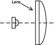
Optical design of the transmissive
-
(5)
The combination of reflective and transmissive: As shown in Fig. 2.17, there are two main forms of design. In the first form, the light of the large angle is reflected by the reflector and then emitted through the lens, and finally, the central ray directly irradiates through the lens. This method is flexible, but inefficient, because the light comes into contact with three surfaces. Therefore, the second form can be used to achieve the desired light distribution effect in some cases. In the second form, the lens is moved close to the LED. The center light is emitted after converted by the lens, and then, the reflector reflects the light of the large angle.
Fig. 2.17 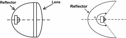
Optical design of the combined reflective and transmissive
-
(6)
Total reflection type optical design: The LED light is irradiated to reflectors in the critical angle and then exported by the optical port in a particular direction and particular perspective. The schematic diagram is shown in Fig. 2.18. This way is regarded as a creative optical design, although not commonly used in practical applications.
Fig. 2.18 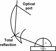
Optical design of total reflection
-
(7)
Second optical design of free-form surfaces: Under normal circumstances, an optical lens is usually used in the optical design of free-form surfaces. Most designs have only a single free-form surface lens, so we must set a surface in the form of a simple curved surface and then design the other surface. A common surface may be a plane, a sphere, or a cylinder. Figure 2.19 shows three common structures used for the free-form surface illumination lens signal:
Fig. 2.19 
Different types of free-form surface lens designs
-
①
The inner surface is a sphere, but the outer surface is a free-form surface. A large angle can be achieved, and thus, more applications can be used in the actual design.
-
②
The inner surface is a plane, but the outer surface is a free-form surface.
-
③
The outer surface is a plane, but the inner surface is a free-form surface. Since the outer surface of a plane is restricted, it is difficult to achieve a wide range of light absorption, but it is easy to clean and it has good visual comfort.
-
①


2.6 Summary
In recent years, China’s LED industry has developed rapidly, and the high growth of markets has also led to advances in technology. Meanwhile, the LED industry has experienced great developments such as the chip, packaging technology, and applications under the strong support of the national and local governments, especially in regard to the strong impetus of the country’s fifteen research programs. The advantages of the LED, such as its small size, pure spectrum, and time control are inherent. These characteristics, unlike traditional sources, help the LED own an unlimited numbers of applications. In addition, improvements in optical efficiency, lower prices, and longevity should be achieved from technical progress. In fact, these aspects are the current direction of LED-based technology research.
LEDs, with their inherent characteristics, such as energy saving, life longevity, shock resistance, fast response, cold light source, and other characteristics, take its place in the fields of indicators, blinkers, displays, landscape lighting, and other fields. In recent years, with the pursuit of semiconductor light-emitting materials research, the multicolored and ultra-high bright LEDs have achieved a breakthrough. In chroma aspects, all colors of visible light have been achieved. Most important of all, the emergence of the ultra-high bright white LED makes it possible so that the applications of LEDs can affect the general lighting market.
In summary, LEDs are a new and efficient solid light source and they have many significant advantages such as a long life, fast response, environmental protection, safety, high luminous efficiency, small size, and narrow spectrum, and they are easy to control. The advent of the LED, in theory, will likely be another leap in the history of mankind’s lighting creations, next in succession to the incandescent, fluorescent, and high-pressure gas discharge lamps.
2.7 LED Driving
2.7.1 The Physical Device of LED Driving
A visible light transmitter and receiver must be used to achieve interaction information, either in the base station or in the terminal equipment of the VLC system. The typical physical devices used in the experimental system include an optical telescope, a VLC transceiver, an interface driver circuit, a signal processing unit, and a power supply system. Since noncoherent light emitted from the LED light source cannot provide a stable carrier, the current VLC link primarily employs a light intensity (IM) and direct detection (DD) method, where the direct-data connection is used as a communication link. On-off keying (OOK), optical-orthogonal frequency division multiplexing (O-OFDM), and other modulation formats can be used in VLC systems.
The functionality of a LED as a transmitter is based on a fast response time and the modulation of visible light for wireless communications. The dual function of LEDs, such as lighting and communication, causes many new and interesting applications to emerge. A LED is a current-driven unidirectional conducting device, and the brightness is proportional to the forward current. In order to ensure the normal operation of the LED, there are several basic requirements as follows:
-
(1)
The input DC voltage drop may not be less than the forward voltage drop of the LED.
-
(2)
The LED driver circuit should be limited to prevent damage since the high current will shorten the LEDs’ life.
-
(3)
There is a certain nonlinear (relationship?) between the LED current and the luminous flux. The current must be controlled into the linear region when we design the VLC system.
-
(4)
The thermal performance of a high-power LED should be noted to prevent damaging the device due to overheating.
-
(5)
The driving circuit should adopt a DC current source or an unidirectional-pulsed current source, rather than a voltage source.
2.7.2 The LED’s Driving Mode
According to the load connections, the white LED driver circuit can be divided into a parallel, a serial, or a serial-type hybrid. According to the type of driving source, the white LED driver circuit can be divided either into a voltage-driven or current-driven source. The usual driver classification of a white LED is a combination of the above two categories and includes four kinds of common power-driven approaches, as follows: the voltage source plus ballast resistor, the current source plus ballast resistor, multiple current sources, or the magnetic boost mode, which all drive a series of LEDs. The advantages and disadvantages of these types of power-driven approaches are shown in Table 2.4.
2.7.3 The LED’s Drive Circuit Design
A LED made by using a special process produces radiation at forward bias, for example, a PN junction semiconductor device, and the V-I characteristic of a LED is similar to a general diode. However, the LED voltage applied to a PN junction is relatively high. Before the forward voltage reaches the rated value \( V_{f} \), the current flowing through the LED is small. When it reaches \( V_{f} \), the current increases very rapidly. Therefore, the LED drive circuit generally employs a constant current source to output a stable light. For example, limiting an element, such as resistors, must be applied to the direct voltage drive.
A LED generally works at DC power, and a LED drive circuit is usually an AC/DC converter. However, a DC/DC converter can also be used in case there is the presence of DC power. Figure 2.20 gives a simple AC/DC converter circuit. Among them, the input voltage is the strongest and the output constant current is about 20 mA. It can drive 10–16 small powered LEDs. The AC 220 V is rectified to the DC by passing the rectifier bridge, and it then pumps down to about 65 V through the MOS transistor switching circuit. Finally, it outputs a 20 mA current to light the LED by the constant current source. Presently, the power of the LED has reached at least 10 W, and also, the power of a single LED package will become increasingly large with the expansion of the LEDs’ general lighting. Therefore, high-power LED driver circuits and high-density integrated circuits will be developed.

Driving circuit of a GU10 16 low-power LED
The LED response time is very short, and the order of magnitude is ns. The light output is substantially proportional to the LEDs’ power input or current input. Thus, LED dimming is just as simple as adjusting the current input. In fact, we can also adjust the LED light output by adjusting the duty ratio of the square wave in the way of PWM, which was the square-wave current used to drive the LED.
References
Wang, Y., Chi, N.: A high-speed bi-directional visible light communication system based on RGB-LED. China Commun. 11(3), 40–44 (2014)
Bass, M., Stryland, E.: Optical society of America, Fiber optics handbook: fiber, devices, and systems for optical communications. Optical Society of America (2001)
Cvijetic, M.: Optical transmission systems engineering. Artech House Publishers (2004)
Sze, S.M., NG, K.K.: Physics of semiconductor devices. Wiley-Interscience (2006)
Manasreh, O.: Semiconductor heterojunctions and nanostructures. McGraw-Hill Education (2005)
JLakowicz, J.R.: Topics in fluorescence spectroscopy. Springer (1991)
Narendran, N., Deng, L.: Performance characteristics of lighting emitting diodes. In: Proceedings of the IESNA Annual Conference, pp. 157–164, Illuminating Engineering Society of North America (2002)
Craford, G.: LEDs a Challenge for Lighting. LEDs a Challenge for Lighting. Light Sources Lumileds Lighting, LLC, 10 (2004)
Tsao, Y.: Solid state lighting: lamps, chips, and materials for tomorrow. IEEE Circuits Devices Mag. 20(3), 28–37 (2014)
Chung, H.Y., Woo, K.Y., Kim, S.J., Kim, T.G.: Improvement of blue InGaN/GaN light-emitting diodes with graded indium composition wells and barriers. Opt. Commun. 331(22), 282–286 (2014)
Den Baars, S.: What is led lighting: technology overview and introduction. DOE SSL Market introduction workshop. Solid-State Lighting and Energy Center (SSLEC), Materials and ECE Departments, University of California, Santa Barbara (UCSB) (2008)
Nazarov, P.M.: Luminescence mechanism of highly efficient YAG and TAG phosphors. Moldavian J. Phys. Sci. (2005)
Thejokalyani, N., Dhoble, S.J.: Novel approaches for energy efficient solid state lighting by rgb organic light emitting diodes—a review. Renew. Sust. Energ. Rev 32(5), 448–467 (2014)
Tsao, Y.: Solid-state lighting. IEEE Circuits Devices Mag. 20, 28–37 (2004)
Author information
Authors and Affiliations
Corresponding author
Rights and permissions
Copyright information
© 2018 Tsinghua University Press, Beijing and Springer-Verlag GmbH Germany
About this chapter

Cite this chapter
Chi, N. (2018). The Transmitter of the Visible Light Communication System. In: LED-Based Visible Light Communications. Signals and Communication Technology. Springer, Berlin, Heidelberg. https://doi.org/10.1007/978-3-662-56660-2_2
Download citation
DOI: https://doi.org/10.1007/978-3-662-56660-2_2
Published:
Publisher Name: Springer, Berlin, Heidelberg
Print ISBN: 978-3-662-56658-9
Online ISBN: 978-3-662-56660-2
eBook Packages: EngineeringEngineering (R0)