
Abstract
As a huge systems engineering project, China Continental Scientific Drilling (CCSD) engineering project consisted of five main sub-projects and one subsidiary sub-project. The five main sub-projects included drilling sub-project, borehole geology and analysis and test sub-project, borehole logging sub-project, geophysics sub-project and information sub-project; while the subsidiary sub-project denoted civil engineering. Among these sub-projects, drilling sub-project was the key, which was the precondition of conducting other sub-projects. Only by obtaining core, rock samples, gas and fluid samples through drilling project could analysis and test sub-project be started and only after borehole completed that a passageway could be available for logging and for geophysical tests, so as to obtain the underground material information. Besides, drilling sub-project was the one which cost the largest investment and the longest time, and with extreme difficulty. Therefore the successful completion of drilling sub-project determined the success of the whole scientific drilling engineering project.
Translated by Geng Junfeng.
Access provided by Autonomous University of Puebla. Download chapter PDF
Keywords
These keywords were added by machine and not by the authors. This process is experimental and the keywords may be updated as the learning algorithm improves.
As a huge systems engineering project, China Continental Scientific Drilling (CCSD) engineering project consisted of five main sub-projects and one subsidiary sub-project. The five main sub-projects included drilling sub-project, borehole geology and analysis and test sub-project, borehole logging sub-project, geophysics sub-project and information sub-project; while the subsidiary sub-project denoted civil engineering. Among these sub-projects, drilling sub-project was the key, which was the precondition of conducting other sub-projects. Only by obtaining core, rock samples, gas and fluid samples through drilling project could analysis and test sub-project be started and only after borehole completed that a passageway could be available for logging and for geophysical tests, so as to obtain the underground material information. Besides, drilling sub-project was the one which cost the largest investment and the longest time, and with extreme difficulty. Therefore the successful completion of drilling sub-project determined the success of the whole scientific drilling engineering project.
Engineering design is the standard for executing the project. The design of drilling sub-project was completed by the design company who won the bid, on the bases of collection of a vast amount of scientific data and research.
2.1 Assignment of Drilling
The overall assignment for constructing the drilling sub-project of the first borehole of China Continental Scientific Drilling engineering project (CCSD-1 Well) was to drill a borehole of 5000 m deep in the ultra high pressure metamorphic crystalline rock formations in Donghai County, Jiangsu Province. Continuous coring was to be conducted for the whole borehole, samples were to be taken and in situ logging carried out.
Technical requirements:
-
1.
Hole depth: 2000 m for the pilot hole and 5000 m for the main hole
-
2.
Final hole diameter: 156 mm
-
3.
Hole deviation: no larger than 14° from 0 to 2000 m and no larger than 18° from 2000 to 5000 m
-
4.
Coring: Continuous coring was to be conducted for the whole borehole, of which
Core recovery should be no less than 80 % for the whole borehole.
Additional core should be taken for complement in case of no core recovered in a long hole section.
Orientational coring should be conducted for one roundtrip in every approximate 100 m.
-
5.
Assist to conduct logging, formation fluid sampling and a variety of in-hole tests
-
6.
Well completion: Casing cementing from 0 to 4800 m and open hole completion from 4800 to 5000 m
-
7.
Borehole geographical coordinates:
The pilot hole: X = 3809.530 km, Y = 40 377.874 km
The main hole: X = 3809.530 km, Y = 40,377.980 km
2.2 Basic Situation of the Well Site
Donghai area borders on the Yellow Sea in the east, and has a semi-humid climate of North China temperature zone, with arid winter, drought spring and autumn, and liable to waterlogging in summer. The yearly average temperature is 13.7 °C, with the maximum temperature of 39.7 °C and the minimum of −18.3 °C. July is the hottest month, with the average temperature of 26.5 °C while the coldest month is January, with the average temperature of −0.6 °C. The annual precipitation is 884 mm, most probably concentrates in July, August and September, accounting for 60 % of the annual precipitation, and the annual evaporation capacity is larger than the annual precipitation. The maximum daily precipitation recorded is 204.5 mm. The annual average thunder and lightning day accounts for 20–30 days most happen from March to October. Freezing season starts from January to March, with the maximum frozen soil depth of 15 mm. In spring and summer often blows east wind and in winter often north wind, with annual average wind speed of 3.2 m/s. The days in which with over force 8 wind (on the Beaufort scale) per year amount to 24.2 days, with the maximum wind speed of 34 m/s (June 18th, 1996).
Donghai area is located in a plain, with smooth terrain. Above the bed rock is covered with loess layer of more than 3 m thick.
2.2.1 Forecast of Lithological Profile of the Formation Encountered
On the basis of massive surface geological survey, trench prospecting, shallow borehole drilling and deep geophysical prospecting, a three dimensional geologic and geophysical model of the drilling area was initially established and the forecast tectonic column of the lithologic units and rocks which would be penetrated through by a 5000 m deep borehole can be found in Fig. 2.1, in which from top to bottom the whole borehole can be divided up into five major units (layers).

The forecast tectonic column of the lithologic units and rocks of CCSD borehole
Unit A: From 0 to 650 m is mainly composed of ultra high pressure eclogite, interbedded with a little thinly laminated biotite-plagioclase gneiss and schist. Many layers of garnet-peridotite may exist at the middle and the lower parts.
Unit B: From 650 to 1930 m mainly consists of different types of gneiss, including, biotite-plagioclase gneiss, epidote-biotite-plagioclase gneiss and granite-gneiss; interbedded with thinly laminated schist, amphibolite and eclogite.
Unit C: From 1930 to 3210 m is mainly composed of aegirine bearing biotite-plagioclase gneiss, with much eclogite and amphibolite or lenticular body.
Unit D: From 3210 to 4550 m mainly consists of eclogite + garnet-peridotite, being the drilling target layer of high wave velocity and high density. All the rocks were formed under the ultra high pressure metamorphic condition of earth mantle, and exhumated to basic and ultrabasic rock layers in shallow earth crust (or large lenticular body).
Unit E: From 4550 to 5000 m is mainly composed of biotite hornblende plagioclase gneiss, probably with little eclogite lenticular body. In comparison with above layer both the wave velocity and the density decrease.
Abovementioned five rock-tectonic units are all separated by tough shear zones with uneven thickness ranging from tens of meters to less than 100 m. In the tough shear zones deformation is intense and foliation develops, the rocks are harder than the upper and lower neighbouring rocks. Due to the stacking of the brittle deformation, tough shear zone may transform into brittle fault zone.
2.3 Lithologic Characteristic of the Rock Formations to be Encountered by Drilling
-
1.
Gneiss is mainly composed of feldspar and quartz, generally with the content of more than 80 %. It may contain little biotite, fasciculate, epidote and muscovite, etc. The rock is of flake granoblastic texture, with gneissose structure which can be divided into orthogneiss and paragneiss, the initial rock of the former is granite while that of the latter is sedimentary rock. Gneiss will be the main lithology at the depth of more than 1000 m both at the main hole and the pilot hole.
-
2.
Eclogite is mainly composed of garnet and acmite, generally with the content of more than 80 %. It may contain little secondary mineral quartz, phengite, cyanite, epidote, clinozoisite, fasciculate and cajuelite, etc. Generally the foliation is not developed, with a block structure. However, a little eclogite experienced intense plastic deformation. Sheet mineral and columnar mineral such as acmite and phengite distribute orientationally and form structural foliation and lineation. According to the content of minor minerals it can be further divided into phengite eclogite, cyanite eclogite, quartz eclogite, ordinary eclogite (very little minor mineral) and cajuelite eclogite. In Maobei area the content of cajuelite in cajuelite eclogite accounts for more than 5 %, being the mother rock of cajuelite mineral. As basically without containing light coloured minerals, this rock has dark colour and high hardness and will be the main rock type of the pilot hole at the depth of less than 1000 m.
-
3.
Peridotite (serpentinized peridotite) is mainly composed of peridotite which contains different amount of garnet, orthopyroxene, clinoaugite and brown mica. It is mostly of grain texture and block structure. This type of rock belongs to ultrabasic rock, with high density and high hardness. Because of the alteration action at later period, peridotite, orthopyroxene and clinoaugite will be transformed into ophite or amesite while garnet will be transformed into amesite and metallic minerals, then the hardness and specific gravity of the rock reduce obviously, sometimes with obvious foliation developed. By inference, peridotite of a certain thickness would be penetrated through both in the pilot hole and the main hole, however, this peridotite would be serpentinized peridotite with different alteration degree.
-
4.
Schist currently exposed at borehole area is mainly muscovite quartz-schist which is mainly composed of quartz and muscovite, with little garnet, cyanite and anorthose. The rock is of granolepidoblastic texture and obvious sheet structure, belongs to the rock layer which easily causes serious hole deviation. However, according to estimation this rock would be hardly seen in both the pilot hole and the main hole.
-
5.
Amphibolite is mainly composed of fasciculate and anorthose, both of which contain approximately same content of mineral, i.e., about 70 % of the rock. The rock contains different amount of minor minerals such as garnet, quartz, muscovite, biotite and epidote. The rock is of prismatic and grain crystalloblastic texture, with foliation developed at different degrees. This rock has two occurring forms, one is occurred in single layer or interbeding with gneiss while the other is formed by retrogressive metamorphism of eclogite and in close paragenesis with eclogite in space.
-
6.
Mylonite Mylonite and cataclastite are tectonite with two different geneses. Mylonite is a product of rock which experienced plastic deformation under relatively high temperature and high pressure. It is a rock of strongly foliated, with obvious mineral lineation developed, being the main component of tough shear zone. The mineral composition of mylonite is basically the same as that of the initial rock before deformation. Schist, gneiss and amphibolite are all the initial rock of mylonite. However, in comparison with the initial rocks, besides the much developed foliation, the mineral grain size of mylonite is finer and the hardness larger. It was estimated that lots of mylonite belts (tough shear zones) would be penetrated through both in the pilot hole and the main hole.
-
7.
Cataclastite Cataclastite (or fault rock), the main composition of fault, is a product of rock which experienced brittle deformation under low temperature and low pressure at the shallow area of the earth’s crust. Based upon the size of the broken rock after rock breaking fault rock can be further divided up into breccia, cataclastite, granulitic rock, powdery rock and fault clay (arranged in order of the size of broken rock piece from large to small). Because of the different cementing ways and bonding materials, the porosity, hardness and density of fault rock varies greatly, and some fault breccias with poor cementation and large porosity may become lost circulation zone.
The borehole position is located in the east boundary of the Maobei eclogite body, and the structure of the borehole area is very complicated. Maobei cajuelite mine is situated at the overturned anticlinal axis, with medium occurrence. The strike of peripheral stratum is totally towards NNE, and the dip angle becomes moderate at the south of the cajuelite mine. In the area faulted structure develops and it is shown from seismic reflection information that there exist underground lots of reverse faults of NNE strike, with SE dip, disrupted by a series of orthogonal normal faults. Besides, in the area develop many series of tough shear zones of NEE strike and exists a series of faults of NW strike, with the character of heave.
According to previous borehole information, it was inferred that following problems would be encountered both in the pilot hole and the main hole of CCSD project.
-
1.
Rock layers are mainly gneiss, eclogite, peridotite, schist, amphibolite, mylonite and cataclastite, with high hardness and poor drillability, generally with drillability grade from 8 to 9, some even from 10 to 11. Peridotite of a certain thickness would be drilled and this rock belongs to ultrabasic rock with high hardness and density. It was inferred that both in the pilot hole and the main hole would be encountered lots of mylonite belts, which is still higher in hardness and with extremely developed foliation.
-
2.
The hardness, density and porosity of fault rock vary greatly and hard and soft rock layers alternately exist.
-
3.
Metamorphic rock, due to uneven metamorphoses, causes a frequent alternation of hard and soft rock layers. With the addition of extremely developed foliation and sheet texture of schist, it would be the rock formation which easily causes serious hole deviation. In this area the maximum stratigraphic dip is 30–35° and the maximum foliation dip is 30–70°.
-
4.
Rock layers with tectonization are unstable, thus precautions must be adopted to prevent hole from collapsing and sticking. Special attention must be paid to the variation of rock formations at the hole sections of 650, 1930, 3210 and 4550 m of the columnar section and appropriate drilling measures should be taken accordingly.
-
5.
In the borehole area fault develops and lots of faults would be encountered in the borehole, and then leakage and blowout would easily happen.
2.4 Drilling Technical Program
Based upon the abovementioned rock formation situation and the technical requirements of the engineering, the basic drilling technique system and the overall construction program must be firstly determined for the drilling engineering design of CCSD-1 Well. On the basis of widely drawing on the scientific drilling experiences of other countries, a complete set of new design concept was adopted for CCSD-1 Well, and three techniques of strategic level, i.e., “combined drilling techniques”, “flexible double hole program” and “advanced open hole drilling program” were put forward and organically combined into a complete set of technical program for scientific drilling in hard crystalline rock with Chinese characteristics. This technical system and construction program of strategic level determined that the concrete construction techniques of operational level were the most important technical strategies to complete the whole project efficiently, safely and economically. These achievements involved overall technical program, borehole structure, selection of drilling equipment, drilling tubing, core drilling techniques, application of hydro-hammer, reaming drilling in hard rock, vertical hole drilling techniques, deviation prevention and correction techniques, side-wall sampling techniques, diamond drill bits, borehole logging, drilling mud, leak protection and anti-plugging, cementation and data collection and treatment.
2.4.1 Combined Drilling Techniques
The combined drilling techniques denote an organic combination of geological diamond core drilling techniques as the main and large scale petroleum drilling equipment as the platform, thus become a new combined drilling technique suitable for scientific drilling, with the advantages of both geological diamond core drilling and petroleum drilling. This technical system adopted thin wall impregnated diamond core drill bit as the main cutting tool, high rotary speed, low bit weight and small pump discharge as the main drilling parameters, to overcome the difficulties in large diameter deep hole continuous core drilling in hard rock formations. It is a new combination to realize high efficient core drilling in hard rock, and a unique system of drilling techniques for scientific drilling.
Geological exploration core drilling techniques are suitable for small diameter comparatively shallow hole continuous core drilling in hard rock formations, with the main methods of impregnated diamond core drill bit, high rotary speed, low bit weight, small pump discharge and small scale equipment. Special drilling technologies such as wireline core drilling and rotary percussive drilling are widely utilized. While in oil drilling, as the equipment has large capability, is suitable for large diameter deep hole drilling, by using non-core drilling with rock bit as the main cutting tool, sometimes with PDC bit. In oil drilling the rotary speed of rotary table, the precision of bit weight control and the proportion of core drilling are low, being suitable for non-core drilling in sedimentary rock layers and unsuitable for continuous core drilling in hard crystalline rocks. It is known that scientific drilling project often need to drill deep hole or super-deep hole in hard crystalline rock formations, for instance, in CCSD-1 Well a borehole of 5000 m deep and with final hole diameter of 156 mm should be drilled in eclogite and gneiss, which can hardly completed by oil drilling techniques or geological core drilling techniques alone. In order to solve the problems of constructing a scientific borehole with large diameter and large depth, the only method was to combine geological core drilling techniques with oil drilling techniques and equipment, i.e., to use combined drilling techniques.
The way to realize this purpose was to install a set of high speed top drive system onto an oil rotary table drill rig, or to install downhole high speed motor onto the downhole drilling tool assembly, so that high rotary speed diamond core drilling could be realized.
Combined drilling technical system was adopted for CCSD-1 Well. ZJ700 electric drill with drilling capacity of 7000 m was used. This drill was produced by Baoji Petroleum Machinery Plant, with advanced level at home. To satisfy the requirement of high rotary speed for diamond wireline core drilling, top drive and wireline coring auxiliary device were to be installed. Wireline core drilling techniques, downhole power percussive rotary drilling techniques and swivel type double tube core drilling tool were used.
2.4.2 Flexible Double Hole Program
There existed lots of undefined factors in China Continental Scientific Drilling project. Through full technical and economic discussion it was decided that a “flexible double hole program” would be adopted. The “double hole program” was a new strategy for scientific deep hole construction, and in KTB in Germany had been adopted the same construction strategy, which denotes that a small size and shallower cored borehole is drilled first near the final target borehole area and then the final target borehole completed, the former is called as pilot hole whereas the latter main hole.
Besides in super deep hole, the “double hole program” can also be adopted in constructing deep hole of 4000–5000 m, where the depth of the pilot hole is only 1000–2000 m.
The double hole program for CCSD project can be found in Fig. 2.2. The designed depth of the pilot hole was 2000, 106 m from the main hole, which was designed 5000 m deep.

The double hole program for CCSD-1 Well
Different from the double hole program in Germany, the double hole program in China was a flexible one, either possibly double hole or single hole, decided by the result of pilot hole construction. Under the circumstances that the construction quality of the pilot hole is good and borehole deviation is controlled within the allowable limits, the main hole can be directly drilled at the pilot hole position, without moving borehole site. What is necessary to do is to directly ream the pilot hole and set casing. The later construction can be conducted according to the design of the main hole, and in such a way “the two holes are combined into one” and double hole drilling is changed into one hole drilling, thus large funds and much time saved. On the contrary, if the casing program in the pilot hole is rather complicated or hole deviation is serious double holes must be drilled, that is, to drill the main hole at the location 106 m away from the pilot hole.
The “flexible double hole program” was designed in accordance with the concrete conditions of CCSD-1 Well and it was essentially a complete set of overall program of flexible application of the two construction procedures based upon different construction results.
2.4.3 Feel Ahead Open Hole Drilling Techniques
In the area of CCSD-1 Well location according to historical record the deepest borehole drilled was no deeper than 1100 m and for the geological information of 1100 m deeper the reference materials from neighboring wells were unavailable. Though surface geological work and geophysical reconnaissance were widely conducted the inferred underground condition was still untrustworthy because of the complexity of underground condition and the interpretation ambiguity of geophysical reconnaissance. Under the circumstances of unknown deep geological conditions and inadequate basis for borehole design, the adoption of “feel ahead open hole drilling method” was the optimum program for borehole construction, because its effectiveness was verified in the former Soviet Union as this construction program had been basically adopted for scientific drilling in crystalline rocks. In consideration of economy, the diameter of core drilling for CCSD-1 Well was designed to be 156 mm, instead of 215.9 mm adopted in the former Soviet Union.
2.5 Borehole Structure and Casing Program
For scientific drilling, either for single hole program or for double hole program, detailed pre-drilling data and materials are unavailable. For borehole structure design, stress must be laid on two factors, i.e. down hole safety and drilling cost, and adequate casing program must be prepared so as to isolate complicated layers. To guarantee to successfully reach to the designed borehole depth, double hole program was adopted in the initial design of the borehole program to deal with serious hole deviation and other complicated situations. In the main hole structure double tail pipe was prepared to solve a variety of difficulties which may occur in drilling process. In the main hole, except that the setting depth of surface casing, intermediate casing and completion casing was basically determined, the setting depth of 219.1 mm tail pipe and 177.8 mm tail pipe was not yet determined. Whether setting these two casings and the setting depth would be decided based upon the concrete conditions at drill site.
Metamorphic layer is of good stability. According to the scientific drilling experiences from the former Soviet Union and other countries, ultra long open hole drilling was possible in CCSD project. If so, it may be unnecessary to set 219.1 and 177.8 mm tail pipe, as well as 273.0 mm intermediate casing. Only running completion casing in 156 mm borehole was necessary. In this way casings could be saved. Furthermore, if intermediate casing was unnecessarily run until about 2000 m deep after the second opening of the pilot hole, then the double holes could be combined into one, i.e., the borehole structure of the pilot hole after the second opening could be constructed in accordance with the borehole structure of the main hole after the second opening and then the repeated construction of the upper hole section of the main hole was saved. The surface structure design (hole diameter was 444.5 mm and surface casing 339.7 mm) of the pilot hole provided possibility for this conversion.
2.5.1 Designed Borehole Structure and Casing Program for the Pilot Hole
The designed borehole structure and casing program for the pilot hole can be found in Table 2.1; Fig. 2.3.

Borehole structure and casing program for the pilot hole
2.5.2 Designed Borehole Structure and Casing Program for the Main Hole
The designed borehole structure and casing program for the main hole can be found in Table 2.2; Fig. 2.4.

Borehole structure and casing program for the main hole
2.6 Drilling Equipment Program
In the light of the requirement of full hole coring in CCSD project, geological drilling equipment was unable to undertake 5000 m hole drilling and in this case petroleum drilling equipment must be employed, however, the conventional coring techniques used in oil drilling industry were unable to be effectively utilized for full hole coring. Therefore, for the pilot hole and the main hole drilling a combined drilling technique (geological drilling + oil drilling) was to be used, i.e., a set of high speed (300–500 rpm) rotary top drive system and wireline coring system were installed onto a rotary table oil drill rig, so as to realize diamond wireline core drilling for large diameter deep hole. In addition, wireline coring system for core drilling needs a high precision for bit feeding, small discharge capacity of drilling fluid and wireline fishing tools. Corollary equipment should be installed and modification should be conducted on the selected oil drill in order to satisfy the needs of scientific drilling.
2.6.1 Main Drilling Equipment
Under the prerequisite to satisfy the needs of drilling CCSD-1 Well, the selected drill should be advanced and economical to a certain extent, mainly satisfying the following conditions:
-
1.
Need of drilling depth should be satisfied: to 5000 m with 156 mm drilling tool.
-
2.
Hook load should meet the need of lifting the heaviest drill string, and at the same time has adequate intake of tensile force to satisfy the requirement of treating complicated situations. The maximum drill string weight is 145 and 126 t after minus buoyant force; the maximum casing string weight is 170 t (273 mm casing set to 2000 m deep), and 150 t after minus buoyant force.
-
3.
Need of special drilling technologies should be satisfied: to satisfy the requirement of wireline core drilling high speed driving device should be equipped, such as Varco high speed top drive, which requires a 43 m high derrick.
Drills which can satisfy the abovementioned requirements include ZJ45, ZJ70L and ZJ70D and after technical and economic analyses it was believed that advanced and economical ZJ70D drill, with adequate drilling capacity (included the capacity to treat accidents and complicated situations), should be selected for drilling CCSD project. As CCSD project would last a long time, drill rig with low daily cost has much economic value. If ZJ45 drill could be technically modified and then meet the need of the construction, it would have much application value. In this case ZJ45 drill was selected as the alternate.
The auxiliary 3NB1600 electric driven mud pump has a maximum working pressure of 34.4 Mpa, with control of stepless change from 0 to maximum stroke realized, can work at a small discharge rate for a long time, thus the requirements of small discharge rate and high circulation pressure for wireline coring can be satisfied.
ZJ70D drill has a 5000 m bailing drum, which can be used as wireline hoist, to meet the needs of core fishing and deviation survey at fixed point.
Equipped with ZJ70D drill is a three stage solid control system consists of oscillating screen, desander (desilter) and centrifugal, among which two sets of oscillating screen are available and 200 mesh screen cloth can be used to meet the need of drilling fluid solid control for wireline core drilling.
Commonly used drilling parameter gauges and data collection system are the necessity for driller to operate the equipment. To satisfy the needs of scientific drilling, at least the ZJC-B2 eight drilling parameter gauge should be equipped with the drill. This gauge can continuously measure and record eight engineering data, including hook load, drilling footage, pump pressure, rotary speed of rotary table, torque of rotary table, pump speed, torque of tongs and outlet discharge of drilling fluid.
2.6.2 Equipment and Instruments Should Be Added
-
1.
High speed top drive
In general, the rotary linear velocity of drill bit should be 1.5–3.0 m/s (equivalent to 184–367 rpm of rotary speed of rotary table) to guarantee an effective drilling of 156 mm impregnated diamond drill bit, and this requirement the conventional oil rotary table and commonly used top drive cannot satisfy. High top drive must be equipped.
-
2.
High precision automatic bit feeding device
In core drilling the requirement of diamond drill bit to bit pressure control is very high, thus an automatic bit feeding device with precision of no less than 500 kg should be equipped. Three types of the device were available and it was recommended that the electronic driller device manufactured by M/D TOTCO Tool Company be used.
-
3.
Compound logging instrument
In order to obtain the related data fully and accurately it was necessary to equip an oil drilling compound logging device. Based on the material information of core and chips, and in combination with drill time variation, stratigraphic profile can be timely established by the compound logging device. Gas bearing abnormal interval of strata in the borehole can be classified through monitoring total gas and methane content variation by chromatographic logging. Fluid property in the borehole can be comprehensively judged according to the aquosity of core and chips, surface gas bearing index, strata gas bearing index in combination with non-hydrocarbon gas content, drilling fluid change and fluid level show in pit (ditch). The abnormal events in drilling construction can be interpreted and forecast through real-time monitoring borehole and drilling fluid data. Therefore compound logging is the necessary auxiliary logging method for scientific drilling and such device should be equipped. In design SDL-9000 compound logging device was selected.
2.7 Drilling String Program
The main types of drilling tools used in drilling construction included:
139.7 mm non-coupling wireline drill rod and 146 mm wireline drill collar, 89 and 127 mm conventional oil drill pipe, different sizes of drill collar and casing.
The drill string may be used for non-core drilling and reaming drilling included two types: 89 and 127 mm oil drill strings. In drill string design the following problems should be mainly considered:
-
1.
Drill rod should meet the need of tensile strength and torsional strength, in which,
The strength of 89 mm drill string should satisfy the need of deviation correction in 5000 m deep in 156 mm borehole.
The strength of 127 mm drill string should satisfy the need of reaming drilling in 4 500 m deep in 200 mm borehole.
-
2.
The quantity of drill collars should satisfy the need of putting weight on bit; the size of drill collars should be suitable for deviation prevention, deviation correction and milling operations after drill pipe sticking.
-
3.
The design of lower drilling tool assembly should satisfy the needs of deviation prevention and deviation correction.
-
4.
For this hole drilling, the clearance between the drill string and the borehole wall and the inside diameter of the drilling tool should be considered in selection of the drill string, to decrease the resistance of drilling fluid circulation and the surge pressure created by tripping.
-
5.
Considering that scientific drilling would last a long period (3–5 years), the outer surface of the selected drill string sub and pin and box thread should be of wear resistance, with good sealing and pressure bearing capacities, to reduce the possibility of drilling tool and casing accidents.
2.8 Core Drilling Program
A variety of core drilling techniques were adopted in design so as to satisfy the requirements of full hole coring for CCSD project.
-
1.
Conventional core drilling was to be used when borehole was shallow.
-
2.
Conventional wireline core drilling was to be employed when borehole reached to a certain depth, so as to decrease tripping time and increase drilling efficiency.
-
3.
Downhole motor wireline core drilling (two combined into one) was to be employed when borehole was relatively deep, rotating torque was large and surface driving could not be used.
-
4.
Conventional downhole motor core drilling was to be used in case that downhole motor wireline core drilling tool was not well prepared.
-
5.
Hydro-hammer drilling, including hydro-hammer wireline core drilling (two combined into one) and conventional hydro-hammer core drilling were to be adopted in order to increase drilling rate in hard rocks.
-
6.
Packed hole drilling tool assembly should be adopted for all the core drilling techniques so as to prevent hole deviation.
2.8.1 Wireline Core Drilling
To increase core recovery and decrease auxiliary drilling time, wireline core drilling system was widely utilized for scientific drilling projects in the countries of the world. Besides reduced tripping time and decreased cost, wireline core drilling system has the following advantages:
-
1.
With improved core recovery and quality, the scientific research purpose of this project can be still better satisfied.
-
2.
Logging instruments can be lowered by utilizing internal flush drill rod and drawworks.
-
3.
Inner tube structure can be changed in accordance with the variation of rock layer.
-
4.
Labour intensity of the operators can be reduced.
Based upon the Drilling Purpose of China Continental Scientific Drilling Project, the Designed Task of China Scientific Drilling Engineering Project and Additional Appendix, the Feasibility Study Report on China Scientific Drilling Engineering Project and the Bidding Document on Engineering Design for China Scientific Drilling Project, full hole coring was required. In consideration of techniques and economy, wireline core drilling system was determined as the optimum core drilling system in the design stage.
In comparison with the wireline core drill rod and drilling tool made in Japan, German made products had obvious superiority both in mechanical properties and in price. For this reason it was mapped out that the wireline coring system used for CCSD project would be imported from a certain foreign company in Germany. International standards were to be adopted for the materials used for the imported wireline core drill rod and the material used for drill rod body was just the same as that used in KTB project (API5D-G105). To guarantee a long antifatigue life and high safety factor for break-out, steel grade for drill rod sub should be high and the material should be 30CrNiMo8 (equivalent to S135 in API Standard). All the pipes must be seamless. The structure of wireline core drill rod and drill collar can be found in Fig. 2.5.

Wireline core drill rod and drill collar
The internal and external upset structure was adopted for drill rod, which was a significant improvement comparing with the external flush structure used in KTB project. The internal and external upset structure has the following characteristics:
-
1.
The reliability of wellhead clamping can be improved For wireline core drilling techniques used in hard rocks, the annular area for rock crushing should be decreased as much as possible in order to increase penetration rate, for instance, the wireline diamond drill bit used in KTB project had an outside diameter of 152.4 mm and an inside diameter of 94 mm. As the drill rod had an outside diameter of 139.7 mm, the annular clearance between drill rod and unilateral hole wall was 6.35 mm only. Because the outside diameter of drill rod sub was as the same as that of drill rod (external flush drill rod), clamping of drill rod could only be realized by using frictional or similar modes, instead of the safe modes such as tongs or fork. For this frictional mode, once the teeth of slips were worn off and friction force decreased obviously, drill string very easily became out of brake and then downhole accident happened. To overcome this, in CCSD core drilling tool design, a certain foreign company was required to produce the wireline core drill rod with both ends internally and externally upset, with an outside diameter of 146 mm for upset end, that is, there was a 3 mm shoulder on each side. As the drill rod sub was also 146 mm in size, once drill string became out of brake the shoulder would move down on the slips, which increased the holding force under the action of the back chamfer, and in this way the accident such as drill string running would be avoided (Fig. 2.6).
Fig. 2.6 
Wireline drill rod clamped by slips
-
2.
The connection strength of drill rod thread can be increased The wireline drill rod used in KTB was only internal upset, with thread thickness (total thickness of pin and box thread) of (139.7 − 110)/2 = 14.85 mm. While for CCSD project the wireline drill rod used had a thread thickness (total thickness of pin and box thread) of (146 − 110)/2 = 18.0 mm, with the ultimate tensile load increased to 2200 kN from 2144 kN (from the Operation Guide of SK146 × 94 mm Wireline Drilling Tool for CCSD Project, August 2002).

This drilling tool consists of two parts, i.e. wireline outer tube and wireline inner tube assembly (see Fig. 2.7), and at the upper part of the inner tube assembly is installed a dip angle inclinometer, with positioning alarm and core blockage alarm, with specifications shown in Table 2.3.

The imported wireline core drilling tool
2.8.2 Hydro-hammer Wireline Core Drilling Tool
Percussive rock fragmentation is the most effective way to increase penetration rate in hard rock formations. Though cone bit can produce percussion while in rotation, it is of low drilling rate and short service life in drilling rocks with drillability over 7–8 grade, because tungsten carbide used for its cutting elements. Diamond is brittle, but in application of diamond drill bit the drilling efficiency can be greatly improved under an appropriate percussive force which doesn’t damage diamond. From this principle the method of diamond percussive rotary drilling emerged. In CCSD-1 Well project KS156 hydro-hammer wireline core drilling tool developed by the Institute of Exploration Techniques was employed (Fig. 2.8), with the specifications shown in Table 2.4.

Structure of KS156 hydro-hammer wireline core drilling tool. 1 Spear head, 2 Spring clip clamp, 3 Spring clip support, 4 Sealing sub, 5 Spring clip chamber, 6 Splined shaft, 7 Spline sleeve, 8 Outer tube, 9 Spring, 10 Power transmitting block, 11 Positioning probe, 12 Independent sub, 13 Bearing, 14 Upper separating adapter, 15 Separating ring, 16 Lower separating adapter, 17 Steel ball, 18 Nut, 19 Core barrel adapter, 20 Core barrel, 21 Core catcher seat, 22 Catching ring, 23 Core catcher, 24 Drill bit
2.8.3 PDM Wireline Core Drilling Tool
For wireline core drilling, it is required to drive the rotation of the whole drilling tool system from surface, thus consuming enormous energy to overcome the friction between the drilling tool and borehole wall. As to diamond wireline coring the high rotation still accelerates the consumption of energy and produces serious disturbance to borehole wall, easily resulting in accidents such as rock piece falling or drill pipe sticking. Downhole power is driven by drill mud, only rotating drill bit and core barrel, and the whole drill string doesn’t rotate or only slowly rotates (to overcome the loss of bit weight). For this reason in the period of early study a program of combining downhole power and wireline coring was put forward. In this project LS156 PDM wireline core drilling tool assembly developed by the Institute of Exploration Techniques was to be utilized. This drilling tool assembly consists of the outer tube assembly and the wireline core drilling tool inner tube assembly combined with PDM, with the structure and principle shown in Fig. 2.9. The specifications of PDM wireline core drilling tool are shown in Table 2.5 and the main specifications of PDM used for the drilling tool can be found in Table 2.6.

Structure of LS156 PDM wireline core drilling tool
2.8.4 Turbomotor Wireline Core Drilling Tool
Either PDM or turbomotor can be downhole power. In this project SV156 turbine wireline core drilling tool assembly developed by the Institute of Exploration Techniques was used. This drilling tool assembly consists of the outer tube assembly and the wireline drilling tool inner tube assembly combined with turbomotor (see Fig. 2.10), with the specifications shown in Table 2.7.

Structure of SV156 turbo-drill wireline core drilling tool. 1 Spear head, 2 Outer tube assembly, 3 Upper spring clip package, 4 Flow plugging package, 5 Turbomotor, 6 Small bearing, 7 Large bearing, 8 Torque transmitting device, 9 Lower plugging device, 10 Drill bit and coring vessel assembly
2.8.5 Conventional Core Drilling Tool
The conventional core drilling tool adopted in this project was selected in accordance to the Standard GB/T16950-1977, that is, S sized (139.7 mm) double tube drilling tool (see Fig. 2.11) of P type diamond core drilling double tube core barrel drilling tool (double tube drilling tool), with the main specifications shown in Table 2.8.

Structure of S sized double tube core drilling tool in P type
2.8.6 Hydro-hammer Core Drilling Tool
To increase drilling rate for conventional core drilling technique, percussive rotary drilling method was to be employed. YZX127 hydro-hammer (Fig. 2.12) manufactured by the Institute of Exploration Techniques would be adopted, the specifications of the tool can be found in Table 2.9.

Structure of YZX127 hydro-hammer. 1 Upper adaptor, 2 Pressure limiting valve, 3 Upper valve, 4 Upper piston, 5 Core valve, 6 Hammer, 7 Anvil, 8 Spline sleeve, 9. Splined shaft
2.8.7 PDM Core Drilling Tool
In conventional core drilling, PDM or turbomotor can be used to drive the core drilling tool at hole bottom. As impregnated diamond drill bit is used, LZ127 × 3.5 PDM with higher rotation speed was selected, the structure of which is illustrated in Fig. 2.13 and the specifications can be found in Table 2.10.

Structure of PDM. 1 Overflow valve body, 2 Overflow valve core, 3 Stator, 4 Rotor, 5 Cardan, 6 Bending outer tube, 7 Water passing joint, 8 Upper radial bearing package, 9 Upper bearing tube, 10. Bearing package, 11. Step bearing, 12. Lower bearing tube, 13 Lower radial bearing package, 14 Transmission shaft
2.8.8 Design Program of Diamond Core Drill Bit and Reaming Shell
-
1.
Selection of diamond core drill bit
In accordance with the drillability, abrasiveness and crumbliness degree of the rock formations which would be encountered in borehole drilling, by reference to the standards of diamond drill bit selection recommended in related regulations and based on the experiences in the pilot hole drilling of CCSD project, priority should be given to the utilization of impregnated diamond drill bit, with the technical parameters should satisfy the following requirements.
-
1.
Drill bit outside diameter 156 mm.
-
2.
Drill bit inside diameter 94 mm for wireline core drill bit and 108 mm for conventional core drill bit.
-
3.
Diamond grain size 35–40 mesh was recommended by reference to the Core Drilling Regulations (1983 version) issued by the former Ministry of Geology and Mineral Resources.
-
4.
Diamond monocrystal strength The monocrystal strength of selected diamond should be larger than 343 N, i.e. equivalent to SMD 35 synthetic diamond or even higher (reference to the National Standards on Diamond issued by the former National Bureau of Standards on May 20th, 1986).
-
5.
Matrix hardness of drill bit HRC 35–45 was determined according to the recommended value in the Core Drilling Regulations (1983 version) issued by the former Ministry of Geology and Mineral Resources.
-
6.
Water opening and slot In design of water opening and slot the application of drill mud and downhole motor should be fully considered and in this way the cross section of water opening and slot should be appropriately enlarged and the quantity of water opening and slot be increased (10–16 water openings and water slots, the projected area of water openings accounts for 40–50 % of the annular rock fragmentation area) so as to reduce the flow resistance and ensure a full cooling for drill bit (Fig. 2.14).
Fig. 2.14 
Recommended structure for diamond drill bit
-
7.
Bit face profile Based on different drilling methods and drillability of the rock formations four bit face profiles were recommended from tens of bit face profiles (round face profile was mainly used for diamond core drill bit in German KTB project).

For step face profile (Fig. 2.15a), a variety of profiles such as single step, double step and triple step are available, normally used for thick wall drill bit such as wireline core drill bit, which crushes rock in larger area and with good stability, being suitable for drilling medium hard rock. In hard rock with weak abrasiveness this drill bit can still obtain a satisfactory result.

Four recommended face profiles for diamond drill bit. a Step profile. b Inner conical. c Saw teeth profile. d Round profile
Drill bit with inner conical profile (Fig. 2.15b) has good stability and guidance at hole bottom, thus being favourable for preventing hole deviation. This profile is often adopted for wireline core drill bit.
Concentric saw teeth profile (Fig. 2.15c), also called as concentric sharp slot profile has large rock fragmentation area, and thus has a combined rock crushing action of grinding and shearing, with coarse cuttings produced, which are favourable to diamond exposure. The drill bit requires less axial weight on bit, and this is favourable to deviation prevention. Saw teeth profile drill bit is suitable for drilling in hard and compact rock formation with weak abrasiveness.
Round profile (Fig. 2.15d) is suitable for the rock formations with high abrasiveness.
-
2.
Selection of diamond reaming shell
Diamond reaming shell is used for trimming the borehole size and stabilizing the drilling tool. It was decided that impregnated diamond reaming shell would be used by reference to the selection of diamond drill bit. Spiral reaming shell with good functions of water discharge and cuttings discharge was selected. The diamond quality used for manufacture of reaming shell was equivalent to that used for diamond drill bit.
Diamond reaming shell products with unified specifications and properties were to be used for different drilling methods and different rock formations, i.e. outside diameter of the reaming shell was 156.3–156.5 mm, with 8–10 water slots, 35–40 mesh diamond grain size and approximate HRC 40 matrix hardness. The overflow area should be 45–50 % larger than the cross sectional area of the annular space between drilling tool and borehole wall.
2.9 Hole Deviation Control Program
Due to the lithological characteristics at well location, hole deviation and dogleg were the major factors which would affect the construction schedule. Thus the control standards for hole deviation and dogleg should be reasonably designed under the preconditions that the requirements of CCSD project could be satisfied and drilling cost reduced.
As the pilot hole was 2000 m deep and the cored hole section of the main hole was started from 2000 m, the deviation standard for the cored hole section could be appropriately relaxed. During core drilling operations, because of high rotary speed and small annular space, the dogleg in this hole section should be as small as possible, to prevent an excessive dogleg from increasing friction resistance for the drilling tool, which might cause an accident of drilling tool breaking. For the upper hole section of the main hole in which non-core drilling was conducted by using oil drilling technique, petroleum drilling standards could be executed for dogleg control. However, for a smooth drilling in the lower hole section of the main hole, it was required that hole deviation at the upper hole section of the main hole should be as small as possible and the hole trajectory should be controlled as smooth as possible. In accordance to this principle a standard for controlling borehole quality was laid down to reasonably control the drilling cost.
-
For the pilot hole:
-
0–1000 m, vertex angle ≤5°, maximum dogleg ≤1(°)/30 m
-
1000–2000 m, vertex angle ≤14°, maximum dogleg ≤ 1(°)/30 m
-
For the main hole:
-
0–2000 m, vertex angle ≤2° to 5°, maximum dogleg ≤2(°)/30 m
-
2000–5000 m, vertex angle ≤18°, maximum dogleg ≤1(°)/30 m
2.9.1 Deviation Prevention for Cored Hole Section and Monitor Measures
In core drilling the related parts of the packed hole drilling tool should be checked up at regular intervals, drilling parameters should be adjusted in time according to different situations so as to decrease deviation intensity. At the same time effective deviation monitor measure should be adopted to avoid excessive hole deviation.
-
1.
In core drilling, make the widest use of conical profile core drill bit.
-
2.
The outside diameter of diamond drill bit and reaming shell must be strictly inspected and any one exceeding regulation should be changed in time.
-
3.
The straightness of the lower drill collar should be observed in lifting drill string and any one bending must be thrown off in time.
-
4.
Weight on bit should be adjusted in time according to drilling speed change and drilling in soft and hard rock interface should be carefully treated.
-
5.
Weight on bit should be reduced in drilling fractured layer (bit bouncing happens).
-
6.
Hole deviation should be timely surveyed.
2.9.2 Deviation Control Measure for Cored Hole Section
Deviation correction by using wire deviation survey-while-drilling techniques is an effective and economical way to control hole deviation and it could be used according to the borehole situation in case of deviation exceeding standard.
2.9.3 Deviation Control Measure for the Upper Section of the Main Hole Where Non-core Drilling Was Conducted
In non-core drilling hole section the conventional anti-deviation techniques in oil drilling could be employed, however, hole deviation would easily happen in drilling with conventional petroleum anti-deviation techniques in crystalline rocks. In order to improve anti-deviation efficiency, in this scientific drilling project the VDS automatic vertical drilling system (Fig. 2.16) was used as the main technique and conventional petroleum anti-deviation techniques was used as subsidiary to control hole deviation.

VDS-3 vertical drilling system
For subsidiary anti-deviation measure, hydro-hammer technique combined with conventional petroleum anti-deviation technique was used to improve anti-deviation result. It was a supplement to VDS system.
2.10 Non-core Drilling and Reaming Drilling Program
It was known from the borehole program and construction procedure that non-core drilling would be conducted in the upper section of the main hole and in the deviation correction section of backfilled small borehole. For other hole sections core drilling would be carried on by using 156 mm drill bit and then reaming when necessary. Petroleum drilling techniques were utilized for non-core drilling and reaming drilling.
For the large diameter non-coring upper section of the main hole, staged reaming techniques would be used because direct drilling in hard rock formation which easily caused hole deviation by using large sized drill bit would result in a low drilling speed and poor anti-deviation effect. Deviation was hard to be corrected once hole deviation appeared and the cost would be rather high. Therefore, opening the hole with conventional sized drill bit and then reaming in stages to the designed hole size was a common technique used for continental scientific drilling in the world.
2.10.1 Design of Drilling Tool Assembly For Non-core Drilling
It was very easy for borehole to become deviated because stratigraphic dip is larger than 30°, anisotropy of rock layers varies greatly and the hard rock contains mica. Under these circumstances two problems were mainly considered in the design of non-core drilling tool assembly for the upper section of the main hole: (1) anti-deviation and deviation correction; (2) improving penetration rate.
Rigid packed drilling tool assembly for oil drilling and VDS (vertical drilling system) employed in KTB were to be used for anti-deviation, in which 203.2 mm thick drill collar and four stabilizers were equipped to the packed drilling tool to increase its rigidity and thus improve its holding (anti-deviation) capacity. Hydro-hammer (impactor) should be used as much as possible in order to improve efficiency of rock fragmentation in hard formation and increase penetration rate. Furthermore, selection of the outside diameter of the drill collar above stabilizer should satisfy the requirement of milling operation after drill pipe sticking and the length of the drill collar was decided by the maximum weight on bit used. As with effective capacity to prevent hole deviation, VDS was utilized as the main anti-deviation and deviation correction tool in the upper section of the main hole while pendulum drilling tool and power tool + bending sub tool was used as an auxiliary measure for deviation correction.
A structure of advanced double stabilizer pendulum drilling tool +hydro-hammer was adopted for pendulum drilling tool, which utilized 203.2 mm thick drill collar to increase pendulum force and improve deviation correction result. The use of hydro-hammer was for the purposes of reducing drill bit weight, increasing drilling rate and improving deviation correction effect. Moreover, selection of the outside diameter of the drill collar above stabilizer should meet the need of milling operation after drill pipe sticking and the length of the drill collar was decided by the maximum weight on bit used.
Non-core drilling was also conducted for deviation correction in 156 mm backfilled borehole. VDS could not be used as the minimum hole size it is suitable to was 215.9 mm. In such small sized borehole the pendulum force and rigidity of the drilling tool were greatly decreased and the pendulum drilling tool could not effectively correct hole deviation. Therefore, only power tool + bending sub could be used for deviation correction in 156 mm backfilled borehole and in order to keep the dogleg not exceeding the designed requirement a “single sub” was used instead of conventional PDM and sub, and in this way the dogleg could be reduced in combination with rotary drilling. Hydro-hammer could be used to increase drilling rate. Selection of the outside diameter of the drill collar should meet the need of milling operation after drill pipe sticking and the length of the drill collar was decided by the maximum weight on bit used.
2.10.2 Design of Drilling Tool Assembly for Reaming Drilling
Because reaming drilling was to be conducted under the precondition that the drilled small sized borehole had satisfied the requirement, therefore in the design of reaming drilling tool the problems of anti-deviation and deviation correction were not taken into consideration and what considered were the problems of downhole safety and how to increase drilling speed.
Selection of the outside diameter of the drill collar should satisfy the requirement of milling operation after drill pipe sticking.
The length of the drill collar was decided by the maximum weight on bit used.
Hydro-hammer could be used in order to increase penetration rate in hard rock.
2.10.3 Selection of Non-core Drill Bit
Selection of drill bit denotes the selection of adaptability of drill bit to rock layers, with purpose that the selected drill bit adapts to rock layer, so a high drilling rate can be obtained, the service life of drill bit prolonged and drilling cost reduced.
Information of international continental scientific drilling shows roller cone bit or button bit can be used for non-core drilling in hard rock layers with high abrasiveness. As the frequent variation of the hard and soft layers of metamorphic crystalline rock which is unlike sedimentary rock that can keep relatively stable in a certain interval, wide range drill bit should be emphasized. Drill bit should be selected in accordance with the drillability and the compressive resistance of the rock, by reference to the bit type recommended by the manufacturer based upon the physical properties of the rock to be drilled.
By comprehensively considering all factors it was decided that type H617–H727 or HJ617–HJ727 roller cone bits were to be used for non-core drilling while SKHA617–SKHA717 roller cone bits were to be employed for reaming drilling.
2.10.4 Design of Reaming Drill Bit
Design of reaming drill bit included the design of reaming size series, the design of adaptability of the reaming part to the rock layer and the selection of pilot bit type, in which,
-
1.
The design of reaming size series Rock fragmented volume, drilling speed, prevention of bit accident and influence of bit accident on bit service life should be considered. The series of reaming size also affects drilling efficiency as too much reaming size grade though increases penetration rate yet the times of reaming are also increased, leading to an unsatisfactory comprehensive drilling result, while too less reaming size grade would reduce reaming efficiency.
-
2.
The design of adaptability of the reaming part of the drill bit to the rock layer Like the drill bit selection for non-core drilling, roller cone reaming bit (Fig. 2.17) was the best choice. Equipped with hydro-hammer with large impact power, button reaming bit could be selected for use.
Fig. 2.17 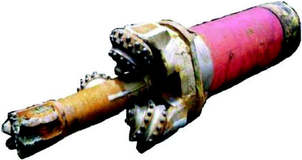
Reaming drill bit
-
3.
The selection of pilot bit type As reaming was conducted under the precondition that the quality of the original borehole was up to standard thus there did not exist the problem of borehole deviation control. Because the pilot bit only served the functions of piloting, breaking the large pieces of fallen stone and clearing away the settled sand, tungsten carbide structure should be used for the pilot bit (see Fig. 2.17).

2.11 Drilling Fluid Technique and Solid Control Program
2.11.1 The Main Technical Problems Should Be Considered
-
1.
The selected treating agent should reduce as much as possible the influence on the analysis of formation fluid The addition of any treating agent will exert influence on the analysis of formation fluid. Treating agent with less influence should be selected for use under the precondition that safe drilling can be guaranteed.
-
2.
Scaling at inner wall of drill rod The well known scaling forms include extended scaling, scaling at vortex area, filtration scaling, eccentric scaling and spiral scaling, among which the extended scaling exerts the largest influence. Scaling at inner wall of drill rod is mainly produced by drilling tool rotation, concentration and size of solid grains in drilling fluid, and surface adsorption of solid grains. Scaling at inner wall of drill rod will seriously affect the smooth uplifting of wireline core barrel.
-
3.
High circulating pressure consumption results from small annular clearance The annular clearance for wireline core drilling is only 5–8 mm and this annular clearance will become even small in case of filter cake existence, causing very high annular circulating pressure drop, rock avalanche at fractured zone caused by high suction pressure and formation leakage caused by high surge pressure.
-
4.
Solid control As the most harmful solid in drilling fluid, cuttings will affect the properties of drilling fluid in the whole process of drilling, increasing density, viscosity, yield point, filter loss, mud cake, abrasiveness, glutinousness and flow resistance of drilling fluid, decreasing drilling speed and increasing rotary table torque. In wireline core drilling, the increase of cuttings will accelerate scaling at pipe wall.
-
5.
Formation leakage and borehole wall sloughing High stress metamorphic rock zone would be drilled in this borehole. Fault and fractured zone would easily cause lost circulation and borehole wall out of stable, resulting in complicated downhole situations. Spilling of formation liquid probably results in pressure kick or blowout. Thus in drilling process attention should be paid to leak protection and anti-sloughing, as well as blowout prevention.
-
6.
Drilling tool wear Small annular clearance and high rotary speed will easily cause an increase of the friction among formation, drilling tool and casing, thus accelerating the wear of drilling tool.
-
7.
High temperature 150 °C high temperature will exert unfavourable influence upon the flow pattern and oiliness of the most drilling fluids and upon the anti-scaling additives. The drilling fluid additive selected must stand a high temperature environment above 150 °C, with properties kept stable.
Basic requirements for drilling fluid:
-
1.
In coring, drilling fluid should have good anti-scaling property, oiliness and rheology property.
-
2.
In reaming drilling or non-core drilling, drilling fluid should also have good cuttings carrying capacity.
-
3.
In deep drilling, drilling fluid should also have good property of temperature resistance.
-
4.
Should be equipped with complete solid control equipment and appropriate measures.
-
5.
Technical measures for preventing and treating circulation loss and borehole wall sloughing should be available.
-
6.
Anti-brine contamination The employed drilling fluid system should maintain good stability under the condition of 10 % NaCl.
2.11.2 Design of Drilling Fluid Type
-
1.
Surface drilling (0–100 m, 444.5 mm hole size)
Drilling fluid system: common water base drilling fluid
Drilling fluid make-up and mud maintaining treatment agent: NV-1 artificial bentonite, PAC-141 thickening fluid loss reducer and NaOH
-
2.
Core drilling
Drilling fluid system: polymer drilling fluid
Drilling fluid make-up and mud maintaining treatment agent: LBM low viscosity extender, JT888 anti-sloughing fluid loss reducer, RH-3 lubricant, RH-4 cleaning agent, XY-27 thinner and NaOH
-
3.
Reaming/non-core drilling
Well depth: 0–3000 m
-
1.
Drilling fluid system: polymer drilling fluid
-
2.
Drilling fluid make-up and mud maintaining treatment agent: NV-1 artificial bentonite, PAC-141 thickening fluid loss reducer, RH-3 lubricant, SK-III thinner and NaOH
Well depth: 3000–5000 m
-
1.
Drilling fluid system: polysulfonate drilling fluid
-
2.
Drilling fluid make-up and mud maintaining treatment agent: NV-1 artificial bentonite, PAC-141 thickening fluid loss reducer, SMP anti-high temperature fluid loss reducer, RH-3 lubricant, SK-III thinner and NaOH.
-
1.
2.11.3 Solid Control
-
1.
Solid control equipment adopted in design included oscillating screen, desander, desilter and centrifuge.
-
2.
For surface drilling, 60–100 mesh oscillating screen was continuously utilized, and desander, desilter (with 200 mesh screen) and centrifuge were used.
-
3.
For core drilling, 200 mesh oscillating screen was continuously utilized, and desilter (with 200 mesh screen) and centrifuge were used.
-
4.
For reaming/non-core drilling, 100 mesh oscillating screen was continuously utilized, and desander, desilter and centrifuge could be intermittently used.
-
5.
Analyses of solid content and constituent must be made every day and then relevant measures could be adopted based upon the analytical results.
2.12 Well Cementation and Completion Program
2.12.1 Well Cementation Program
-
1.
According to the design of borehole structure, well cementation was to be conducted based on two programs; the first program denoted a design of five layers of casing run in a single borehole and in the second program which was a double hole program three layers of casing were to be run in the pilot hole (Table 2.11) and five layers of casing run in the main hole (Table 2.12).
Table 2.11 Design of casing program in the pilot hole Table 2.12 Design of casing program in the main hole -
2.
In design of cement slurry, the problems of leakage and improvement of slurry displacement efficiency in narrow clearance should be put into consideration (Figs. 2.18 and 2.19).
Fig. 2.18 
Cement slurry design for the pilot hole
Fig. 2.19 
Cement slurry design for the main hole
-
3.
Requirements for cement slurry total properties


It was required that 60 min should be added for cement slurry thickening time on the base of construction time.
It was required that cement slurry should have good rheology property because of the large friction drag in cementing and in cement slurry displacement resulted from small annular clearance in cementation of 127, 177.8 and 219.1 mm tail pipes.
For well cementation deeper than 3500 m with high formation static temperature (>110 °C) sand cement slurry system was to be adopted to prevent cement slurry from strength retrogression due to high temperature.
API filter loss of cement slurry for tail pipe cementation should be less than 100 ml.
Considering that leakage might happen in cementing in this borehole, the experiment of low density cement slurry system should be well made in advance besides the preparation of conventional density cement slurry system.
24 h compressive strength of the cement slurry should be larger than 14.0 MPa.
It was recommended that MTC cementation was to be used in 219.1 mm casing cementation in the main hole, based upon the technical requirement of small annulus cementation, in combination with the technical characteristics of drilling mud transforming into cement slurry.
2.12.2 Principle in Design of Casing String Strength
-
1.
Designed safety factor
Safety factor of tension (St): 1.8
Safety factor of collapsing (Sc): 1.125
Safety factor of internal pressure strength (Si): 1.1
-
2.
Calculation of external load
Calculation model for strength: two-dimensional stress model
Calculation method for buoyance: buoyance factor method
In calculation of effective external squeezing force, the following factors should be considered: (1) inside casing 50 % space was emptied (for 219.1 mm technical tail pipe and 177.8 mm × 4500 m moving casing, 1/3 was emptied). (2) Full hole saturated salt water (density 1.15 g/cm3) was used in calculation of fluid column pressure outside casing. (3) Mud density (1.05 g/cm3) was used for the pressure outside casing in calculation of internal pressure.
Calculation method of internal pressure: based on oil well kick.
-
3.
Other factors should be considered
-
1.
Under the condition that external load was satisfied, design should be made based upon the method of minimum cost.
-
2.
Selection of casing thread: TM thread was used for moving casing and 177.8 mm extreme-line casing and trapezoidal thread for other casings.
-
3.
As 156 mm drill bit was to be used for final hole drilling, in selecting the wall thickness of different casings the drift diameter must satisfy the requirement of drill bit diameter for next step hole opening.
2.12.3 Well Completion Operation
After well cementation with 127 mm tail pipe, to avoid the opened hole section being filled with some cement slurry and then long-term observation instrument could not be set down, the cementing techniques of casing packer + differential pressure stage collar was employed. The packer was to be set before cement injection and then the differential pressure stage collar at the top of casing packer was opened and cement slurry was injected at the top of casing packer. After 48 h curing cement plug was drilled out by using 73 mm oil tube + 89 mm drill collar × 110 m + 89 mm PDM + 108 mm drill bit, then the borehole was completed and with protection liquid injected.
The designed well head device for completion is shown in Fig. 2.20.

Well head device for completion
2.13 Design of Moving Casing
2.13.1 Necessity of Adopting Moving Casing Design
Because lots of undefined factors exist in rock formation, adequate casing program should be prepared in design of borehole structure, so as to deal with the complicated problems may happen. In practical drilling construction, however, drilling cost must be taken into account, thus casing program and setting depth should be adjusted according to actual situation. After running casing each time, drilling with small sized drill bit is conducted first and then reaming is carried on when complicated situation is encountered and casing setting is necessary. This construction method often brings about two harmful results: (1) the annular clearance (between inside wall of casing and drilling tool) at upper hole section is much larger than that (between opened hole and drilling tool) at lower hole section, the consumption of circulating pressure is large in wireline core drilling, discharge capacity is restricted, and mud flowing velocity at upper hole section decelerates. As a result, cuttings cannot be effectively carried out; (2) the drilling tool with high rotation speed is easily broken at the borehole position where hole size suddenly changes (the boundary area of opened hole and casing shoe).
To solve abovementioned problems, moving casing technique was adopted in design, i.e. after the larger sized casing is set another casing with inside diameter slightly larger than drill bit is set in the former larger casing, without cementation and can be retrieved when necessary. This is called as moving casing. In this way the cuttings carrying capacity under restricted discharge capacity at upper hole section can be improved and accident of drilling tool broken caused by collision of high rotation drilling tool against the inside wall of large sized casing can be avoided. Furthermore, as the bearing effect is produced by the movement between drilling tool and casing, accident of casing broken caused by serious wear of drilling tool to fixed casing in long time drilling process can be avoided. So the application of moving casing technique in core drilling in large diameter casing is very necessary and the experiences of scientific drilling in the former Soviet Union and in Germany indicated that this technique was necessary and feasible.
2.13.2 Fixing of Moving Casing
In this design two kinds of thread type single stage casinghead used for oil drilling, i.e. 339.7 mm (133/8 in.) × 177.8 mm (7 in.) and 273.0 mm (or 219.1 mm) × 177.8 mm were to be utilized to solve the problems of upper fixing, suspending and retrieving the moving casing (Figs. 2.21 and 2.22). At the middle position of the moving casing was to be used a rigid centralizer to improve the stability. At the lower position of the moving casing was to be utilized a special double cone casing shoe with large contact surface and water channels to prevent the moving casing from moving downwards. The weight of the casing was separately borne by the upper suspension and the lower holding in a certain proportion, at the initial stage of fixing the upper suspension bore more weight while the weight the lower holding bore would become more along with casing elongation resulted from the increased temperature as borehole was deepened. This variation was still within the design limits.

Fixing of moving casing in the second opening drilling

Fixing of moving casing after the third opening drilling
2.13.3 Safety Management of Moving Casing
Moving casing is under the condition of long-lasting impact and wear of high rotation drilling tool, thus feasible and reasonable precaution, accident treatment and safety inspection programs must be adopted to avoid casing accidents. Furthermore, strict casing safety management measures should be taken.
In the design strict measures were worked out for anti-sticking, anti-breaking and for accident treatment.
2.14 Time and Cost Estimation
2.14.1 Designed Construction Progress
According to the initial design, drilling construction for double-hole program needed 1138 days, in which the pilot hole drilling construction needed 242 days (Table 2.13; Fig. 2.23) and the main hole drilling needed 896 days (Table 2.14; Fig. 2.24). Moreover, the construction before drilling and drill rig moving and installation needed 25 days, and completion logging and geothermal gradient logging needed 20 days. The arrangement of the total construction progress of the whole project can be found in Fig. 2.25.

Construction progress of the pilot hole

Construction progress of the main hole

Overall arrangement of the construction progress of the CCSD project
2.14.2 Budgetary Estimation of Cost
Drilling engineering cost included the corollary tool cost, the construction cost for the pilot hole and the construction cost for the main hole (see Table 2.15). Drill rig daily cost was based on 35,022 RMB Yuan per day and thus the total budgetary resources reached to 96,454,000 RMB Yuan.
2.15 Change and Modification of Design
-
1.
Change of core drilling diameter
As the both ends of 139.7 mm wireline drill rod were upset to 146 mm and the diameter of drill rod sub was also 146 mm, the wall clearance for wireline core drilling was only 5 mm (the clearance at the position of upset ends of drill collar and drill rod, and drill rod sub) and 8.15 mm (the clearance of drill rod body). This clearance was too narrow. To further improve the hydraulic properties of down hole coring tool, decrease annular pressure drop and ensure safety for borehole, the diameter of drill bit was increased 1 mm, i.e. from originally designed 156 to 157 mm.
-
2.
Change of drilling method for the first opening (spudding-in)
Full hole coring was required for CCSD-1 Well to provide complete geological information such as full hole core for geoscientific study. According to this guiding ideology, core drilling method was adopted in the design of the first opening for the pilot hole. However, as many boreholes deeper than 100 m had been drilled in the surrounding area and CCSD-PP2 and test hole constructed near the well site of the main hole, lots of core and geological information were available for reference, cutting logging could be used instead of core, without any influence on geoscientific study. Moreover, by using non-coring method drilling program would be simplified, and drilling construction time and cost would be reduced. Also, non-core drilling in the first opening was beneficial to adopting technical measures to prevent hole deviation. Based upon this actual situation, in the 0–101 m hole section of the first opening (spudding-in), non-core drilling with 444.5 mm roller cone drill bit equipped with heavy collar was conducted and cutting sample was fished out every meter for geoscientific study, whereas the original design (core drilling first and then reaming in steps) was abandoned.
-
3.
Change of borehole structure and casing program
In the process of ascertaining the main materials before starting the construction, it was found out that in the design of the fourth layer of casing string 177.8 mm (7 in) thin wall (δ = 8.065 mm) extreme-line casing was to be employed, which could only be imported from Japan because it was an unconventional type and thus unavailable in China. Although the Japanese company was capable of producing the casing jet they were unwilling to because of our less quantity. In this connection, the borehole structure was appropriately changed by the designer at the request of China Continental Scientific Drilling Engineering Centre. The original third layer casing (244.5 mm drill bit × 219.1 mm casing) and the fourth layer casing (200 mm drill bit × 177.8 mm extreme-line casing) were combined into one layer casing, i.e. 244.5 mm (95/8 in) drill bit × 193.7 mm (75/8 in) casing. The changed hole structure is shown in Table 2.16 and in Fig. 2.26.

The changed design of borehole structure and casing program
Author information
Authors and Affiliations
Corresponding author
Rights and permissions
Copyright information
© 2015 Science Press, Beijing and Springer-Verlag Berlin Heidelberg 2015
About this chapter
Cite this chapter
Wang, D. et al. (2015). Drilling Engineering Design. In: The China Continental Scientific Drilling Project. Springer Geology. Springer, Berlin, Heidelberg. https://doi.org/10.1007/978-3-662-46557-8_2
Download citation
DOI: https://doi.org/10.1007/978-3-662-46557-8_2
Published:
Publisher Name: Springer, Berlin, Heidelberg
Print ISBN: 978-3-662-46556-1
Online ISBN: 978-3-662-46557-8
eBook Packages: Earth and Environmental ScienceEarth and Environmental Science (R0)