
Abstract
This chapter illustrates a practical radiation protection problem experienced at an installation of the second PET/CT equipment at a nuclear medicine department. It had to be installed in an existing building and where the choice of localities had to be done for reasons other than radiation protection. The process and the methods for calculations and measurements are described and references made to up-to-date reports describing shielding calculation methodologies for PET and X-ray facilities.
Access provided by Autonomous University of Puebla. Download chapter PDF
Keywords
These keywords were added by machine and not by the authors. This process is experimental and the keywords may be updated as the learning algorithm improves.
1 Introduction
Practical radiation protection can be quite challenging. An often-encountered problem is the installation of new equipment in existing buildings that are not well suited for the specific purpose. This chapter deals with some of the radiation protection issues that came up when installing a PET/CT system.
Diagnostic radiological equipment like a CT scanner only radiates in the room where the equipment is installed. This is different for nuclear medicine. Here, the patient is the source of radiation, and patients cannot be “shielded” or constrained to a single room. Therefore, the legislation covering radiological equipment is often more rigorous than the legislation concerned with unsealed sources in nuclear medicine.
The example presented here is inspired by the circumstances at Bispebjerg Hospital in Copenhagen, Denmark. The Department of Clinical Physiology and Nuclear Medicine had received funds for acquiring a second PET/CT system. A room was allocated for installation of the scanner, and additionally, another room was to be rebuilt as uptake room for patients administered with 18F-FDG. For the sake of understanding, the sample calculations here are simplified.
2 PET/CT System
The room for installation of the combined PET/CT system was chosen for reasons other than radiation protection. A PET/CT system is quite heavy (about 5 ton), occupies a lot of space (considerably more than 20 m2), relies on controlled and stable ambient environment (cooling!) while consuming a lot of electric energy (but heat dissipation is unevenly distributed over a working day), should be easily accessible for staff and patients, and much more. Radiation protection is usually secondary in negotiations with the management, architects, and entrepreneurs and often not considered beforehand. Similarly, the room to be used as uptake room was the only room of sufficient size that was available. Ideally, such a room is in close proximity to the scanner, but this was not possible here.
The second scanner was placed such that the operator room could be shared with the first scanner (see Fig. 9.1). For radiation protection purposes, two kinds of radiation (and sets of legislation) must be distinguished: 511 keV annihilation radiation from PET radionuclides (unsealed sources) and scattered radiation from the CT scanner (X-ray). In addition, relevant scenarios for occupational exposure must be selected.

Layout of the room for PET/CT #2 with adjacent rooms. The operator room is shared with PET/CT #1. For estimation of the dose contribution of the annihilation radiation, a radioactive source was placed in the “head” end of the patient bed (see radioactivity symbol) and the dose rate at the desk in the office measured. The thick orange line denotes the reinforced wall that was built to reduce the dose to the office staff
The neighboring rooms of the scanner include operator room, parking lot outside the building, office, and corridor. Applicable occupancy factors for these areas can be looked up [1]. Often, neighboring rooms can be left out in shielding calculations. That can be the case if these rooms are scarcely occupied or not occupied at all. However, care must be taken that regularly occupied rooms next to the ignored rooms are taken into consideration, for example, if there is a small litter room between the radiation source and an office.
2.1 Annihilation Radiation Around the Scanner Room
As the new scanner room is neighboring an office where secretaries work throughout the day, exposure should be estimated. A simple experiment was performed, placing a vial containing 200 MBq 18F-FDG in the scanner room (where the head of a patient would be placed when completely in the scanner) and measuring the dose rate at the secretary’s chair—which was about 6 μSv/h (Fig. 9.1). This clearly is an overestimation of the actual dose rate, as the activity is not concentrated in the head and the patient is most of the time further away from the secretary’s desk.
With an expected 1,500 patients/year, N, in that scanner, 400 MBq injected activity (having decayed to about 260 MBq, A, 1–1.5 h postinjection) and a transit time, T, of about 30 min, this would yield an estimated annual dose, D A, of about 6 mSv—clearly unacceptable for a secretary:
A reduction to 10 %, that is, accepting a maximum annual dose of 0.6 mSv, demands reinforcing the wall with 16 mm lead or 20 cm concrete [2]. The latter is actually feasible as an extra wall often can be raised without many problems (thick orange line in Fig. 9.1).
With respect to other areas around the PET/CT room, it should be noted that the distances to the patient are much larger, that is, the radiation field is much weaker or the occupancy much lower. Thus, all other areas were excluded from further calculations. The operator room also benefits from the required shielding against the scattered CT radiation, discussed in the next paragraph.
2.2 CT Radiation Around the Scanner Room
Legally imposed shielding requirements of a CT installation are usually fulfilled by ensuring 2 mm lead-equivalent shielding around the scanner. In this case, this was fulfilled at several places (due to sufficient wall thickness) but impractical at other places, so a more detailed investigation was required. However, measurement of scattered CT radiation with sufficient accuracy is often very difficult as the imposed radiation limits are very low.
Thus, shielding requirements were calculated based on the radiation scatter cart provided by the manufacturer and modeled transmission curves of scattered radiation from CT through lead [1]. An important parameter in this context is the CT workload, that is, the total radiation generated by the CT X-ray tube. Here, a workload of 4,000,000 mAs/year corresponding to more than 1,500 patients was assumed. The typical variety of CT protocols with the corresponding exposure settings (duration, current, and voltage) was investigated based on the experience from the first PET/CT system. For each area around the PET/CT room, occupational factors were considered.
The result was that extra shielding was only necessary between scanner and operators (2 mm lead equivalent) and at the entrance to the scanner room from the corridor (1 mm lead equivalent). During the rebuilding of the room, all doors were purchased with 2 mm lead equivalent anyway—as that option was less expensive.
2.2.1 Annihilation Radiation in and Around the Uptake Room
After injection with 18F-FDG, patients should rest about 1 h in a relaxing environment. The uptake room, which was established for that purpose, offers space for four patients. Adjacent rooms—having functions like server room, staff toilet, etc.—are in general not occupied by persons and are thus ignored in the further calculation because of their low occupancy.
The total dose D at distance d integrating over uptake time (t U) received from a single patient injected with activity A 0 can be estimated [2]:
Physical decay of 18F is taken into account by a reduction factor \( {R_{{{t_{\rm {U}}}}}} \). As “realistic” worst-case situation we take:
-
PET/CT systems with an annual workload of 2 × 1,500 patients
-
Two hundred and twenty workdays, that is, about 70 patients/week
-
Administered activity A 0: 400 MBq 18F-FDG (administered activity for a 70 kg standard patient is normally below 300 MBq)
-
One-hour rest/uptake (t U) after injection (decay: \( {R_{{{t_{\rm {U}}}}}} = 0.{83} \))
The necessary reduction factor of a shielding arrangement limiting the radiation to a maximum dose rate \( {\dot{P}_{{\max }}} \) (averaged over uptake time t U with an occupancy factor T) at distance d is
Likewise, the reduction factor for a given number of patients, N, over a certain time (e.g., 1 year) and a maximal dose P over the same time is given by
In [2], attenuation coefficients of various materials reducing radiation of 18F are plotted. These plots are of great help for estimation of the shielding potential of materials like lead, iron, and concrete.
With respect to the uptake room here, three relevant scenarios are considered:
-
(1)
A technologist sitting at the table doing some registration and paperwork should be protected from the radiation of the injected patients (Fig. 9.2).
Fig. 9.2 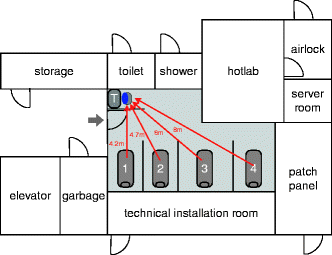
Layout of the uptake room with adjacent rooms. The uptake room provides space for four patient beds and a small desk for a technologist doing paperwork. Distances from the middle of the patient beds to the chair of the technologist (blue dot) are shown. Note that adjacent rooms have low occupancy (shower, toilet, etc.) or are areas with high dose rates (hotlab)
-
(2)
A technologist preparing the injection of the next patient should be protected from radiation of the other patients (Fig. 9.3).
Fig. 9.3 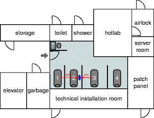
Layout of the uptake room with adjacent rooms. Illustrated is the position of a technologist (blue dot) preparing patient #2 for injection, while patient #1 and patient #3 are resting in their chairs after administration of the radiopharmaceutical
-
(3)
Staff working on the floor above and below the uptake room.


3 Scenarios
3.1 Scenario 1: Technologist Working at Desk
The individual patient areas are not shielded at the feet end of the beds, so radiation from the four patients can reach the desk where the technologist can do some paperwork related to patient handling during the uptake period. While working there, staff may not be aware of working in a radiation field; thus, the area around the desk must be shielded. Constant exposure at the desk must not lead to unacceptable exposure of staff. Accepting a total dose of 0.3 mSv/month accumulated during 20 7 h working days, the average dose rate must not exceed \( (0.3{\hbox{mSv/month)/}}(20 \times 7{\hbox{h/month)}} \approx 2\;{\hbox{\rm mu Sv/h}} \).
Each patient contributes during the stay in the uptake room with
The radiation field of each patient at distance d is thus
The distance of the middle of each patient bed to the desk was measured to be 4.2, 4.7, 6, and 8 m, respectively, yielding a total dose rate of 4.5 μSv/h. A reduction to 2 μSv/h (44 %) requires 6 mm lead (or 3 cm iron) in the shielding wall at the desk.
This calculation does not take into account scattered radiation from floor, ceiling, and walls. Reasoning from simple measurements with a vial containing 4.5 GBq 18F and some lead bricks, this contribution was neglected.
3.2 Scenario 2: Technologist Taking Care of Patient (Before 18F-FDG Administration)
The distance to the closest two patients is about 2 and 3 m, corresponding to a dose rate of about 8 and 4 μSv/h, respectively, that is, 12 μSv/h in total. Reduction to 2 μSv/h (16 %) demands 13 mm lead (or 5 cm iron) to be placed in the walls between patient beds. Again, scattered radiation is ignored.
3.3 Scenario 3: Staff on Floor Above and Below
The floors above and below the uptake room must not be forgotten. Fortunately, below the room, there is only storage space. Above the room, however, there are several offices. Depending on national legislation, occupational exposure of non-related workers must not exceed an annual maximum dose of 0.3 mSv.
We take the same hypothetic situation as above, that is, 3,000 patients evenly distributed over four beds, all injected with 400 MBq 18F-FDG. The distance from the bed to the ceiling is 2.2 m, the ceiling itself was assumed to be made of 15 cm concrete.
Considering the dose profile 2.85 m above the patient bed (in offices, people usually sit on chairs—see also [2]) and having distances between patient beds of 2, 3, and 3 m, the annual accumulated dose is just below 0.9 mSv for a person working at the “peak position” on the floor above during the same working hours as the PET technologists. This model takes into account the penetration angle of the radiation from the middle of the patient bed through concrete ceiling (Fig. 9.4).

Upper part: Plot of the dose profile on the floor above the uptake room. Lower part: Layout of the uptake room. Note that the x-axis of the plot corresponds to the dashed line in the lower part, that is, the dose rate for a person sitting on a chair in an office on the upper floor right above the green star will be exposed to the maximum dose (red star)
Reducing the radiation to 1/3 (i.e., accepting an annual dose of 0.3 mSv) would take about 8 mm lead or 3–4 cm iron of shielding in the ceiling. This is not very easy to handle, and other solutions for radiation protection should be investigated. Closer inspection of the ceiling revealed that it actually is 20 cm thick, reducing transmission by an additional 50 %. Also, the location of the offices on the floor above was inspected more carefully, revealing both an additional offset in relation to the middle of the patient beds, that is, the effective distance was actually longer by about 2 m. All in all, the additional reduction in exposure was considered sufficient. It also turned out that some of the offices were used for other purposes with much lower occupancies—but that should not be relied on. It is difficult to control the use of offices belonging to other departments.
4 Conclusion
Practical radiation protection is often difficult to perform. This chapter has listed some examples of somewhat realistic situations in which radiation protection principles can be applied.
References
NCRP (2004) Structural shielding design for medical X-ray imaging facilities. NRCP report no. 147. http://www.ncrponline.org/
Madsen MT, Anderson JA, Halama JR, Kleck J, Simpkin DJ, Votaw JR, Wendt RE III, Williams LE, Yester M (2006) AAPM task group 108: PET and PET/CT shielding requirements. Med Phys 33(1):4–15
Author information
Authors and Affiliations
Corresponding author
Editor information
Editors and Affiliations
Rights and permissions
Copyright information
© 2013 Springer-Verlag Berlin Heidelberg
About this chapter
Cite this chapter
Lonsdale, M.N. (2013). Examples of Shielding Calculations for a PET/CT Installation. In: Mattsson, S., Hoeschen, C. (eds) Radiation Protection in Nuclear Medicine. Springer, Berlin, Heidelberg. https://doi.org/10.1007/978-3-642-31167-3_9
Download citation
DOI: https://doi.org/10.1007/978-3-642-31167-3_9
Published:
Publisher Name: Springer, Berlin, Heidelberg
Print ISBN: 978-3-642-31166-6
Online ISBN: 978-3-642-31167-3
eBook Packages: MedicineMedicine (R0)