
Abstract
The craniovertebral junction is the region of the spine with the highest local mobility. With 40° of unilateral axial rotation, the C1–C2 joint is crucial for everyday head rotation. The large diameter of the upper spinal canal allows any physiological movement without compromise of the spinal cord. Strong ligaments like the transverse ligament of C1 and the alar ligaments of C2 combined with strong joint capsules ensure that the bony elements stay in position. When this system is disturbed, acute as well as chronic irritations of the spinal cord can cause neurological disturbances up to a transverse spinal cord syndrome. In most cases, instability triggers these symptoms. A minor symptom, indicating malfunction of the upper cervical spine, is neck pain, which can extend up to the occiput. Insufficiency of the transverse ligament, for example, in rheumatoid arthritis raises the risk of spinal cord compression during flexion of the cervical spine. Progressive destruction of C0–C1–C2 joints can be followed by a compressive myelopathy or a basilar invagination. Further nontraumatic causes of malfunction in the craniovertebral junction are congenital or developmental malformations, tumors, and infections or degenerative diseases.
Access provided by Autonomous University of Puebla. Download chapter PDF
Keywords
- Cervical Spine
- Transverse Ligament
- Transarticular Screwing
- Basilar Invagination
- Craniovertebral Junction
These keywords were added by machine and not by the authors. This process is experimental and the keywords may be updated as the learning algorithm improves.
1 Introduction
The craniovertebral junction is the region of the spine with the highest local mobility. With 40° of unilateral axial rotation, the C1–C2 joints are crucial for everyday head rotation [1]. The large diameter of the upper spinal canal allows any physiological movement without compromise of the spinal cord. Strong ligaments like the transverse ligament of C1 and the alar ligaments of C2 combined with strong joint capsules ensure that the bony elements stay in position. When this system is disturbed, acute as well as chronic irritations of the spinal cord can cause neurological disturbances up to a transverse spinal cord syndrome. In most cases, instability triggers these symptoms. A minor symptom, indicating malfunction of the upper cervical spine, is neck pain, which can extend up to the occiput. Insufficiency of the transverse ligament, for example, in rheumatoid arthritis raises the risk of spinal cord compression during flexion of the cervical spine. Progressive destruction of C0–C1–C2 joints can be followed by a compressive myelopathy or a basilar invagination. Further nontraumatic causes of malfunction in the craniovertebral junction are congenital or developmental malformations, tumors, and infections or degenerative diseases.
2 Diagnosis and Nonclinical Preoperative Evaluation
-
MRI is the best imaging modality for the identification of soft tissue changes as well as to detect indirect consequences to the spinal cord. With the additional application of contrast medium, this diagnostic tool is superior in all inflammatory diseases (Fig. 8.1).
Fig. 8.1 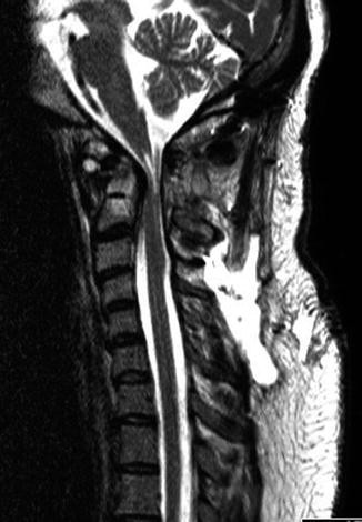
Midsagittal T2-weighted image (WI) of a patient with a high cervical myelopathy due to compression of the high cervical spinal cord by a rheumatoid arthritis (RA) pannus at the C1–C2 level
-
In cases with an indication for stabilizing surgery, CT scan with sagittal and coronal reconstruction of the craniovertebral junction is essential for preoperative planning. It can be used in particular to identify a high-riding vertebral artery in C2, which may have an influence on several screwing techniques. Osteoporosis and inflammatory destruction of the joints can also be evaluated with this imaging modality.
-
To avoid injury to a vertebral artery with an aberrant course, angio-CT or MRA should be done preoperatively [4].
-
X-rays in AP and lateral view will rarely give additional information. For evaluation of instability, flexion/extension X-rays should be performed (Fig. 8.2). The distance between the dorsal edge of the anterior ring of the atlas and the ventral edge of the dens can be measured as the atlanto-dental-interval (ADI). Normal values are distances of 3 mm. Distances up to 5 mm are suggestive for an insufficiency of the transverse ligament. Further increase of the ADI indicates an obvious insufficiency of the alar ligaments. If the ADI is above 10 mm, the transverse ligament should be considered to be ruptured [5].
Fig. 8.2 
Extension/flexion X-rays with increased atlanto-dental interval (ADI) highly suspective for a ruptured transverse ligament. Therefore, this condition should be considered as instable
-
Electrophysiology with SEP and MEP can give information about spinal cord involvement. Additional functional electrophysiology performed preoperatively with flexion and extension maneuvers of the cervical spine may show the dynamic component of intermittent cord compression.


3 Surgical Indications
In general, two surgical treatment strategies are pursued to treat diseases in this region. The first is decompression of the spinal cord by direct or indirect bone removal. The second strategy is stabilization, which addresses increased mobility in the craniovertebral region. In some cases a combined decompressive and stabilizing treatment is necessary (see Chap. 7). Due to its anatomical characteristics, a dorsal approach to the craniovertebral region is preferred. Furthermore, the morbidity of an anterior transoral approach is much higher, mainly due to the high infection rate. During surgery on the craniovertebral junction, it is clear that the approach itself can already induce additional instability. Fixation of the C1–C2 region will significantly reduce the rotational mobility. An occipitocervical fixation additionally reduces flexion and extension. The resultant loss in quality of life for the patient can be greater than what they initially suffered from their primary disease. Therefore, it is important to inform the patient preoperatively for this loss of motion and to adjust the head position in an acceptable direction so that the patient will still be able to face everyday life [6].
-
Atlantoaxial instability in rheumatoid arthritis
-
Craniovertebral arthrosis
-
Inflammatory destruction of the dens (RA, pannus)
-
Os odontoideum
-
Craniovertebral tumors (see Chap. 43)
-
Craniovertebral malformation
-
Chiari malformations (if decompression of the upper cervical spine is necessary or in cases of an assimilation of the atlas)
3.1 Contraindications
-
Atypical course of the vertebral artery
-
High-riding vertebral artery in C2
-
Small isthmus/pars interarticularis at C2
4 Surgical Technique
Technical prerequisites for occipitocervical and C1–C2 stabilizing procedures:
-
Preoperative 3D CT for planning the virtual screw pathways
-
Navigation system (optional)
-
Fluoroscopy
-
Mayfield clamp
-
Cannulated screws (optional)
-
Titanium wiring cable
4.1 General Considerations
-
Several different techniques have been described for successful C1–C2 fixation.
-
Posterior wire fixation according to Gallie’s sublaminar wiring and grafting method or by the Brooks method is widely replaced by screw fixation.
-
Biomechanically, the Magerl technique of transarticular C1–C2 fixation provides the best stability but is technically more demanding than the wiring methods as well as the C1 lateral mass and C2 pedicle screw fixation.
-
The C1 articular mass and C2 pedicle screw with rod fixation as described by Harms and Goel offer in some cases the possibility of C1–C2 rotation, after removal of the osteosynthesis material (once the pathology/fractures are healed).
-
There is no place for halo external fixation in neither of the abovementioned indications.
4.2 Planning, Preparation, and Positioning
Before starting the procedure, an intensive analysis of the craniovertebral region is essential to look for:
-
Congruence of the joints
-
Rotational dislocation
-
Size of the interarticular portion
-
Chondrosis of the joints
-
ADI distance
4.3 Patient Positioning
During the positioning of the patient, these factors have to be considered and adapted:
-
The Mayfield skull clamp should be fixed on the patient’s head while they are still in supine position. Ensure an adequate distance between the clamp and forehead as well as the nose of the patient. Be sure that the patient has not had a previous craniotomy. The transportation stretcher with the patient is positioned beside the operating table. Four people are needed to roll the patient onto the operating table. One should hold the Mayfield clamp and the head. One should stand at the chest and one on the opposite side so that the patient can be rolled on his/her arms for further adjustment on the operating table. The fourth person should stay at the feet of the patient. To reduce the risk of spinal cord compression due to potential instability, keep an external orthosis until the patient is lying safely on the operating table.
-
Derotate accurately the cervical spine (by fluoroscopic control), before fixing the Mayfield clamp at the operation table. This will prevent unnecessary muscular trauma during the incision and will reduce intraoperative bleeding. If there is an increased atlanto-dental interval (ADI), one can try to reduce it already during the positioning of the patient. But keep in mind that flexion in the craniovertebral region means a potential spinal cord compression. On the other hand, extension of the cervical spine might hinder the surgical approach. If flexion is necessary (which will increase the ADI), a maneuver pulling the cervical spine backwards will prevent a compression of the spinal cord.
-
After final positioning of the cervical spine, an AP and lateral fluoroscopy should be performed. Use these to check the estimated drilling directions, because anatomical variations like a prominent kyphosis of the cervicothoracic region may limit the surgical access. The best way to control the positioning will be a 3D scan at this moment. You can use this to evaluate the potential reduction of an increased ADI or dislocated joints. You will have the opportunity to further correct the positioning as well as to decide whether a transarticular or a C1–C2 Harms-Goel technique will be the appropriate stabilization method. If you are able to adjust the ADI completely by preoperative positioning, the Magerl technique can be preferred. If ADI remains elevated, the Harms-Goel technique should be preferred. With this latter technique, you have the opportunity for an additional intraoperative reduction at the time of the rod fixation. Both these techniques will be described later.
-
When the cervical spine is fixed sufficiently, pull the shoulders down slightly and elevate the chest (inverse Trendelenburg position). This will reduce intraoperative venous bleeding [7]. Also, this maneuver may reduce basilar invagination.
5 Tips and Tricks
-
Patients with rheumatoid arthritis often suffer from corticoid-induced skin damage. Avoid direct taping of the skin. Wrap the arms with cotton wool before.
-
After positioning the patient prone with the head fixed by the Mayfield skull clamp, any anesthetic emergency will be difficult to treat. Agree with your anesthetist how you will turn the patient over in an emergency.
-
Leave the transportation stretcher within spitting distance.
-
Because the patient is mostly covered by sterile drape, intraoperative manipulation by the anesthetist is difficult. Therefore, use both invasive blood pressure measurement and the measurement by blood pressure cuff.
6 Surgical Technique
6.1 Approach
-
A midline posterior skin incision and subcutaneous incision are made from the occiput (Inion) to as far distal as necessary, but down to the spinous process of C3 or C4 is seldom necessary (Fig. 8.3).
Fig. 8.3 
Illustration of the midline skin incision and the additional skin incisions lateral to the midline and caudal to C7, if necessary for percutaneous C2 pedicle drilling
-
For occipitocervical arthrodesis, the external occipital protuberance should be exposed with full thickness; lateral and subperiosteal dissection of the muscular attachments of the trapezius and semispinalis capitis muscles should be done. Caudally, cut the subcutaneous tissue as far as the nuchal ligament. Care should be taken to identify and dissect within the nuchal ligament to prevent damage to the underlying muscles and excessive bleeding. Release the splenius and semispinalis muscles from the spinous processes by monopolar electrocautery (Fig. 8.4).
Fig. 8.4 
Anatomical situation after resection of the M. rectus capitis posterior and M. obliquus capitis inferior
-
Dissect bilaterally the lower part of the obliquus capitis inferior muscle and identify the arch of C2.
-
Remove the rectus capitis minor muscle insertions from the dorsal arch of C1. Using blunt dissection, the lamina can be further dissected (Fig. 8.4).
-
Stop when you identify the sulcus of the vertebral artery, at approximately 1.5 cm from the midline. Any attempt to proceed more laterally will cause excessive venous bleeding from the periarterial (vertebral) plexus.
-
When wiring of C1 is planned, remove the atlantoaxial membrane subperiosteally with a sharp dissector.
-
To expose further landmarks, identify the inner cortical border of the isthmus of C2 inserting carefully a nerve hook.
-
For occipitocervical arthrodesis, release the inserting muscles from the lamina of C2 and C3 until you identify the C2/C3 and C3/C4 facet joints.


7 Tips and Tricks
-
The upper cervical muscles insert at the spinous processes. If necessary, you can cut them directly at the bone. Avoid sharp cutting on other places. Respect the tissue layers to minimize tissue damage and bleeding. On the dorsal surface of the lamina, you should carry out a blunt dissection.
7.1 C1–C2 Transarticular Screw Fixation (Magerl) (Fig. 8.5)

(a) Postoperative lateral X-ray after transarticular C1–C2 screwing (Magerl technique) with additional apposition of an autologous bone graft fixed with a titanium wire. (b) Artistic impression of the same condition in lateral (upper) and AP view (lower)
-
For transarticular screwing [3] (Fig. 8.5a, b), the starting point of your drilling is 2–3 mm cephalad to the lower border of the C2 inferior facet joint and 2–3 mm lateral to the medial cortical border of the C2 isthmus (Fig. 8.6).
Fig. 8.6 
(a) Starting point in AP view. (b) Drilling direction for transarticular C1–C2 screwing in lateral view. (c) Screw position at the end of procedure in AP view
-
The entry point can be opened by an awl or, by preference, by a high-speed drill. In cases of high instability, opening with a high-speed drill is most preferable to avoid any additional pressure on the unstable segment (Fig. 8.7).
Fig. 8.7 
Details of the surgical anatomy. The desired screw placement is just lateral to the edge of the spinal canal. It will transverse the isthmus of C2 and the C1–C2 articulation
-
Under lateral fluoroscopy, a guide wire is drilled toward the superior aspect of the anterior C1 ring (Fig. 8.8).
Fig. 8.8 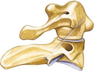
Drilling direction for transarticular C1–C2 screwing (Magerl technique)
-
Depending on the trajectory for this drilling, sometimes an additional percutaneous skin incision at the C7 level is necessary (Figs. 8.3 and 8.9).
Fig. 8.9 
Measurement of the screw length
-
The drilling direction is orientated slightly medially and parallel to the inner wall of the isthmus of C2. The correct direction should be controlled by positioning a nerve hook attached to the inner wall of the isthmus.
-
Screws with a length between 38 and 50 mm are inserted after threading the borehole (Figs. 8.10, 8.11, and 8.12).
Fig. 8.10 
Drilling (With permission of Aesculap AF, Tuttlingen, Germany)
Fig. 8.11 
Tapping and introducing the transarticular screw in the lateral view (With permission of Aesculap, AG, Tuttlingen, Germany)
Fig. 8.12 
Introducing of the transarticular screw in the AP view (With permission of Aesculap AG, Tuttlingen, Germany)


8 Tips and Tricks
-
Chondrosis of the C1–C2 joint will hinder the passage of the guide wire. Drilling with reduced pressure will help. Use continuous fluoroscopy to see that the guide wire keeps the correct trajectory.
-
Keep the guide wire in place, until the screw passed the joint. If you have to reduce a luxation, it will be nearly impossible to recover the burr hole in C1, without the guide wire in place.
-
After the guide wire is positioned transarticularly, use a 3.5 mm drill. The drilling should be done under continuous fluoroscopic view to ensure that the guide wire inside the drill is not moved forward.
-
The transarticular screwing will give a biomechanically very stable construct that will prevent C1–C2 rotation, but flexion will be less controlled. This will result in increased forces on the screws with the risk of implant failure. Therefore, this technique should be combined with an interlaminar fixed bone graft [8, 9] (see below).
8.1 C1 Articular Mass Screw-C2 Pedicle Screw (Harms-Goel)
8.1.1 C2 Screw
-
In the C1–C2 Harms-Goel technique [10], the starting point for the C2 pedicle screw is in the upper part of the pars interarticularis more laterally than the entry point for the transarticular screwing. At the sagittal midline of the C2–C3 facet joint, 3–5 mm cranial to its caudal articulation (with C3), you find the perfect entry point (Fig. 8.13).
Fig. 8.13 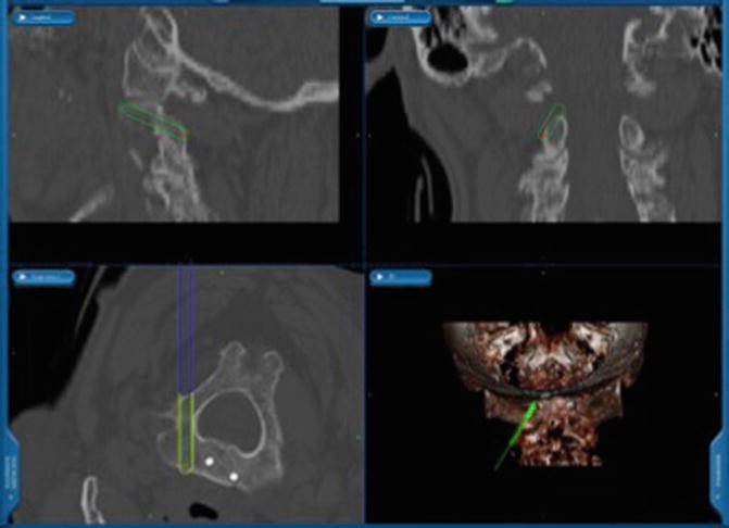
S7 neuronavigation unit (Medtronic, Memphis, USA) view in three planes of the projection of a C2 pars screw. At the axial view (lower left), one can appreciate the spinal canal as well as the vertebral artery
-
After opening the cortical bone, a burr hole is drilled under lateral fluoroscopy.
-
The drilling should be done 20–30° cranially and 20–25° convergent.
-
Alternatively, the starting point for the C2 pars screw is 2 mm superior and lateral to the C2–C3 facet articulation. Then drill in a craniocaudal trajectory and aim at the base of the dens axis in lateral fluoroscopy or use the navigation image on your station (Fig. 8.13).
-
Usually, polyaxial screws with a length of 22–26 mm are inserted.

8.1.2 C1 Screw
-
The C1 screw is a lateral mass screw.
-
Usually, you find the starting point below the posterior lamina of C1 (Fig. 8.14). The starting point for the C1 screw is in the middle of the junction of the C1 posterior arch and the midpoint of the posterior inferior part of the C1 lateral mass (Fig. 8.15).
Fig. 8.14 
Landmarks for the C1 screw insertion, right-sided three-fourth view. Note how far lateral the dissection and the entry point should be done (With permission of Aesculap AG, Tuttlingen, Germany)
Fig. 8.15 
S7 neuronavigation unit (Medtronic, Memphis, USA) view in three planes of the projection of a C1 pars screw. At the axial view (lower left), one can appreciate the spinal canal as well as the vertebral artery. Virtual projection of the screw (yellow) gives an impression of the correct positioning. Existing tip of another screw in the dens axis
-
Coagulate slightly to shrink adhesive tissue. Be careful because damaging the very thin wall of the venous plexus will cause excessive bleeding.
-
The C2 nerve root can be retracted in a caudal direction before drilling or screw insertion.
-
Identify the uppermost point of the dorsal convexity of the lateral mass, as this point often corresponds with the perfect starting point.
-
A drill guide will protect the surrounding tissues (Fig. 8.16).
Fig. 8.16 
Opening the cortical bone by using a bone awl through the guiding tube, lateral view (With permission of Aesculap AG, Tuttlingen, Germany)
-
Drill a guide wire into the lateral mass. This will help you to recover the burr hole even if there is heavy bleeding from the venous plexus. The drilling direction is slightly cranial and one should aim to the middle posterior edge of the anterior C1 arch. In the axial plane, the drilling direction is straightforward.
-
Use a cannulated drill and try to open the anterior cortex to achieve a bicortical screw fixation. Be careful, however; violation through the pharynx may induce infection.
-
The usual longitudinal diameter of the C1 lateral mass in adults is 20 mm.
-
To avoid any damage to the C2 nerve in the C1–C2 foramen by the threads of the screws, partially threaded polyaxial screws can be preferred in the C1 lateral mass. The total length of the screws mostly varies between 28 and 34 mm. The usual width is 3.5–4 mm.
-
To fix the construct, a rod is inserted between C1 and C2 (Fig. 8.17).
Fig. 8.17 
Rod insertion into the variable screwheads of the C1 and C2 screws, lateral view (With permission of Aesculap AG, Tuttlingen, Germany)
-
Using a rod reducer, a C1–C2 luxation can be adjusted.
-
Place the rods in the polyaxial screws and tighten slightly the nuts. By doing so, the polyaxial screw behaves like a monoaxial one. Then, reduction, compression, or distraction can be achieved.


9 Tips and Tricks
-
While exposing the C1 lateral mass, you may cause significant bleeding in this region. Be prepared to this and have some local hemostatic products aside.
-
Electrocautery rarely solves the problem. Use local hematostatics combined with mechanical compression and patience.
-
The venous bleeding usually stops after inserting the screw.
-
To recover a burr hole during venous bleeding is difficult. Therefore, use cannulated screws if possible.
-
To avoid damaging the venous plexus in the interarticular region of C1–C2, an approach through the C1 lamina into the lateral mass is possible. But beware of the pars horizontalis of the vertebral artery.
-
In transarticular screwing as well as in the Harms-Goel technique, the vertebral artery can be damaged while drilling the burr hole. Arterial damage is indicated by a massive pulse synchronous bleeding out of the hole. This bleeding will be stopped by closing the hole with hemostatic agents like Tabotamp (Ethicon, Germany). In these cases, unilateral screwing together with bone graft apposition will give sufficient stability. After surgery, one should perform an angiography to confirm or exclude any damage to the violated vertebral artery.
9.1 C2 Laminar Screws Placement [11]
-
In combination with C1 lateral mass screws, an additional method for treatment of C1–C2 instability is the use of translaminar screws. Intralaminar screws are used as a rescue technique especially in cases with a high-riding vertebral artery or an implant failure in C2. Its advantage is the lack of risk to damage the vertebral artery.
-
The entry point is at the base of spinous process of the C2 lamina.
-
Before you start drilling, you should expose the inner edge of both C2 laminae with a nerve hook to identify the trajectory and to get alerted, once the drill perforates the inner cortex of these laminae.
-
Open the cortical bone with a high-speed 2 mm drill in the cranial third of the base of the spinous process.
-
Repeat this procedure on the opposite side, opening the cortical bone on the caudal third of the base of the spinous process.
-
Manual intralaminar drilling is preferred to a depth of 25–30 mm, heading toward the contralateral C2–C3 facet joint.
-
Use 3.5 mm polyaxial screws with a typical length between 25 and 35 mm.
-
Insert C1 lateral mass screws like described above and connect them with the intralaminar screws by a rod (Fig. 8.18).
Fig. 8.18 
Fixation of the rod into the screwhead by securing the nuts, lateral view

10 Tips and Tricks
-
Drill carefully with low speed through the cancellous bone of the lamina without pushing too much. This will prevent a perforation of the lamina.
-
Leave the nerve hook inside for identification of the inner edge of the lamina during the drilling.
-
While drilling the C2 laminae, fluoroscopy is not helpful. Skip the fluoroscopy during this step to reduce radiation exposure for everyone.
-
Because the position of the screwheads is located medially and outside of the line for subaxial lateral mass or pedicle screwing, this technique might be more helpful in short distance C1–C2 stabilization techniques, rather than for longer constructs. The screwheads at C2, although multiaxial, will never be in line with the others, making rod insertion troublesome.
-
Be careful by the removal of the cortical bone for later bone grafting. The intralaminar screw can be exposed.
-
The reduction of the range of motion (ROM) in this construct is equivalent to the one when using C2 pedicle screws [12].
-
The pullout strength is equivalent to screws placed into the pars interarticularis of C2 [13].
10.1 Occipitocervical Fixation [14] (Fig. 8.19)

Postoperative AP (left) and lateral (right) X-rays after occipitocervical fixation
-
One occipital plate should be used, which can be fixed in the midline of the occiput due to the thickness of the internal crista (Fig. 8.20). Midline screws offer the best bone purchase. Bicortical screws have 50 % greater pullout strength than either unicortical screws or wires.
Fig. 8.20 
Positioning of the occipital plate (right-sided three-fourth view) (With permission of Aesculap AG Tuttlingen, Germany)
-
Additional lateral screw fixation of the plate should be done to resist the rotational forces on the construct. Size the appropriate plate. Plate size should depend on the rod connection to suboccipital screws. Avoid medial-lateral rod bending to meet the C1–C2 screws by appropriately sizing the plate.
-
During the drilling, give counter pressure to the forehead to avoid its pullout from the Mayfield clamp.
-
There should be some remaining occipital bone between the foramen magnum and occipital plate for decortication and later bone graft attachment.
-
For the connection between the occipital plate and the cervical spine, you can insert polyaxial screws using various techniques, which were described previously (pedicle screws, lateral mass screws, C2 translaminar screws) (Fig. 8.21).
Fig. 8.21 
Complete construct after extended occipitocervical fixation (right-sided 3/4 view)
-
The rod must be bent to connect the screws with the occipital plate. Make sure the rod is bent in a way; the patient not all the time will be forced to see the floor or the sky!
-
Because of its sharp bending angle, C1 is usually difficult to include within this construct.
-
If it is necessary to include C1 to the instrumentation, a transarticular C1–C2 screwing technique can be performed, with additional C1–C2 wiring and grafting (Gallie or Brooks).


10.2 Bone Grafting
In cases of nontraumatic instability, an additional bone graft [15] (Fig. 8.22) is mandatory to obtain fusion.

Midsagittal CT scan 10 month after bone grafting showing a perfect posterior C1–C2 fusion
-
You will achieve the best results by autologous bone graft.
-
Remove the cortical bone for implantation from the C1 and C2 laminae. In the C1 lamina, a small notch at the caudal edge will prevent a graft protrusion toward the spinal cord.
-
The bone graft should be notched to hold onto the spinous process of C2 (Fig. 8.23).
Fig. 8.23 
Illustration after transarticular fixation and wiring C1/C2 with additional bone graft between the arch of C1 and C2 (With permission)
-
For fixation of the bone graft, a titanium cable loop is inserted. It passes beneath the dorsal arch of the atlas in the midline caudally to cranially. The loop is then fixed under the lamina of C2. By tightening the cable, the bone graft is clamped between both laminae. Additional cancellous bone graft chips can be used to cover the remaining decorticated areas (Fig. 8.23).
-
To ensure a tight fixation of the wire, it is necessary to partially remove inserting muscles (e.g., interspinous and multifidi muscles) from the spinous process of C2. This is a disadvantage, which can be avoided by adopting the Brooks wiring technique which uses titanium cables that pass on each side beneath the arch of C1 and the lamina of C2 [16].
-
In cases of occipitocervical fixation, parts of the occipital bone as well as laminae and facets should be decorticated. Additionally, the joint capsules are opened.
-
Bone graft chips are attached to all decorticated bony sides.

11 Navigation
Intraoperative 3D navigation is recommended to reduce the risk of vessel damage as well as malpositioning of screws (Fig. 8.24). Also improving safety, navigation provides a less invasive approach with reduced exposure and violation of the intrinsic neck muscles [17, 18]. The reference clamp has to be fixed before starting the instrumentation procedure. For the upper cervical spine, the best position to fix this clamp is the C2 spinous process. To anticipate the orientation of the surgical instruments, the navigation reference frame should be directed cranially. For the transarticular C1–C2 technique, additional fluoroscopy is necessary for the observation of the passage through the joint space and the anterior C1 lamina. When using navigation, be constantly aware that your surgery is being carried under the guidance of a virtual reality. Reality checks at all steps, especially when in doubt, are mandatory.

Intraoperative 3D images performed with the O-arm (Medtronic, Memphis, USA) showing a high-riding vertebral artery in the C2 vertebra on the left side (the center of the green cross)
Editor’s Note on Evidence
Studies regarding surgical treatment of the craniovertebral region can be graded into evidence levels 2 C, D. Multicenter randomized controlled trials at level A have not been published yet.
Conservative treatment with external orthosis will give temporary stabilization but will not solve the problem of persisting instability. Furthermore, this treatment has a high mortality in the elderly, especially after trauma.
Nonrigid fixation techniques relying on cable and wire fixation will give only limited stability at the craniovertebral junction. Dorsal wiring will stop flexion motion but extension as well as lateral bending or rotation will not be reduced sufficiently [2]. The persisting movement in this highly mobile area will be followed by implant failure and nonunion.
A stable fixation at the craniocervical junction has to stop movement in all three planes, which is only possible by constructs with screws and sufficient bone grafts on properly prepared bony structures [3].
References
Maiman D, Yoganandan N (1991) Biomechanics of cervical spine trauma. Clinical neurosurgery. Williams & Wilkins, Baltimore, pp 543–570
Vaccaro AR, Lim MR, Lee JY (2005) Indications for surgery and stabilization techniques of the occipito-cervical junction. Injury 36(Suppl 2):B44–B53
Magerl F, Seeman P (1987) Stable posterior fusion of the atlas and axis by transarticular screw fixation. In: Kehr P, Weidner A (eds) The cervical spine. Springer, New York
Abou Madawi A, Solanki G, Casey AT, Crockard HA (1997) Variation of the groove in the axis vertebra for the vertebral artery. Implications for instrumentation. J Bone Joint Surg 79:820–823
Menezes A, Van Gilder J (1990) Anomalies of the craniovertebral junction. In: JR Y (ed) Neurological surgery. WB Saunders, Philadelphia
Winking M (2014) The rheumatic spine. J Neurol Neurochir Psychiatr 15:82–88
Winking M (2012) Posterior transarticular C1/C2 screw technique. In: Grochulla F, Vieweg U (eds) Manual of spine surgery. Springer, Berlin, pp 187–194
Haid RW Jr (2001) C1–C2 transarticular screw fixation: technical aspects. Neurosurgery 49:71–74
Weidner A (1990) Spinal fusions in rheumatic dislocation of the cranio-cervical transition. Neurochir (Stuttg) 33:50–53
Harms J, Melcher RP (2001) Posterior C1–C2 fusion with polyaxial screw and rod fixation. Spine (Phila Pa 1976) 26:2467–2471
Wright NM (2004) Posterior C2 fixation using bilateral, crossing C2 laminar screws: case series and technical note. J Spinal Disord Tech 17:158–162
Gorek J, Acaroglu E, Berven S, Yousef A, Puttlitz CM (2005) Constructs incorporating intralaminar C2 screws provide rigid stability for atlantoaxial fixation. Spine (Phila Pa 1976) 30:1513–1518
Lehman RA Jr, Dmitriev AE, Helgeson MD, Sasso RC, Kuklo TR, Riew KD (2008) Salvage of C2 pedicle and pars screws using the intralaminar technique: a biomechanical analysis. Spine (Phila Pa 1976) 33:960–965
Dickman C, Douglas R, Sonntag V (1990) Occipitocervical fusion: posterior stabilization of the craniovertebral junction and upper cervical spine. BNI Q 6:2–14
Dickman C, Sonntag V (1993) Wire fixation for the cervical spine: biochemical principles and surgical techniques. BNI Q 9:2–16
Brooks AL, Jenkins EB (1978) Atlanto-axial arthrodesis by the wedge compression method. J Bone Joint Surg Am 60:279–284
Kraus M, von dem Berge S, Perl M, Krischak G, Weckbach S (2014) Accuracy of screw placement and radiation dose in navigated dorsal instrumentation of the cervical spine: a prospective cohort study. Int J Med Robot 10:223–229
Luther N, Iorgulescu JB, Geannette C, Gebhard H, Saleh T, Tsiouris AJ, Hartl R (2015) Comparison of navigated versus non-navigated pedicle screw placement in 260 patients and 1434 screws: screw accuracy, screw size, and the complexity of surgery. J Spinal Disord Tech 28(5):E298–303
Author information
Authors and Affiliations
Corresponding author
Editor information
Editors and Affiliations
Rights and permissions
Copyright information
© 2016 Springer International Publishing Switzerland
About this chapter
Cite this chapter
Winking, M. (2016). Posterior Fixation of the Craniovertebral Junction in Nontraumatic Instability. In: van de Kelft, E. (eds) Surgery of the Spine and Spinal Cord. Springer, Cham. https://doi.org/10.1007/978-3-319-27613-7_8
Download citation
DOI: https://doi.org/10.1007/978-3-319-27613-7_8
Published:
Publisher Name: Springer, Cham
Print ISBN: 978-3-319-27611-3
Online ISBN: 978-3-319-27613-7
eBook Packages: MedicineMedicine (R0)