
Abstract
Large organizations today face a growing challenge of managing heterogeneous process collections containing business processes. Explicit semantics inherent to domain-specific models can help alleviate some of the management challenges. Starting with concept definitions, designers can create domain specific processes and eventually generate industry-standard BPMN for use in BPMS solutions. However, any of these artefacts (concepts, domain processes and BPMN) can be modified by various stakeholders and changes done by one person may influence models used by others. There is therefore a need for tool support to aid in keeping track of changes done and their impacts on different stakeholders. In this paper we present an approach towards providing such support based on a semantic layer that records the provenance of the information and accordingly propagates impacts of changes to related resources, and illustrate the applicability of the approach via an illustrative example.
Access provided by Autonomous University of Puebla. Download conference paper PDF
Keywords
1 Introduction
Large organizations today face a growing challenge of managing heterogeneous process collections containing business processes that correspond to various practices and domains. When growing by acquisition or indeed by diversifying in new areas, new business processes need to be added to the company portfolio and it is often extremely difficult to match and preserve their semantics in the context of the existing practices.
Explicit semantics inherent to domain-specific models can help alleviate some of the management challenges and as [1, 2] argue, it is essential that domain-specific models be the starting point in business process design. Starting with concept definitions, designers can create domain specific processes and eventually generate industry-standard Business Process Modelling Notation BPMN [3] for use in BPM Software (BPMS) solutions. These various business process modelling layers are illustrated in Fig. 1.

SOA modelling layers in relation to business processes
These layers can be connected through a layer that we call the Inter-Layer Connection Bridge (ILCB), as illustrated in the left-hand side of Fig. 2 and detailed in [4].

Overview of proposed components
In such an approach, the connectivity layer is responsible for taking modelling artifacts (process files, organizational structures, process activity properties) from a variety of tools in their respective form, and generating related artifacts used by other tools. For instance, the process definition from a domain specific editor can be transformed into a BPMN process definition for any BPMN2 editor. This is needed because the various viewpoints in a business process modelling suites require different representations but they fundamentally pertain to the same elements.
Any of these artefacts (concepts, domain processes and BPMN) can be modified by various stakeholders. For instance when a business process needs to be improved, domain experts may enact changes on the domain process level. Any such changes in any layer may or may not influence models used in the other layers. Whether or not changes propagate to other layers (and how much) is determined by the transformation semantics between layers. However, today when looking at a large collection of processes it is almost impossible for various stakeholders to understand problems with process evolutions, changes, differences or inconsistencies with business goals. There is therefore a need for tool support to address their questions based on their own concerns and perspectives (business vs. architect vs. technical…).
In the rest of the paper we present an approach towards providing such support based on a semantic layer that records the provenance of the information and accordingly propagates impacts of changes in any of the related resources in one or more of the presented layers.
2 Overview of Proposed Solution
This paper presents a solution to the above-mentioned problems by externalizing the required information in a semantic space. This space has three main roles:
-
Storing all the transformation traces, when they occur.
-
Using inference to generate useful knowledge about process models in their various representation forms (domain-specific, BPMN).
-
Responding to queries about process models, at any level and returning results associated to the various points of view of the various stakeholders.
Figure 2 illustrates the semantic space proposed in this work (i.e. the green vertical boxes to the right-hand side of the image).
The semantic space includes a Semantic Representation System (SRS) and an associated Query and Reporting System (QRS) as explained in the following sections.
3 Semantic Representation System
The SRS preserves a consistent representation of all the main artefacts in the various business process modelling layers (left part of Fig. 2) as well as their interrelations. The source of information for the SRS is the Inter-Layer Connection Bridge (ILCB) presented in Fig. 2, which sends relevant data each time a new transformation occurs. Upon receiving such data, the SRS checks the consistency of the data and infers new facts.
The artefacts that constitute the backbone of the SRS system are generated based on the following:
-
1.
a direct mapping of information that can be extracted from the ILCB Metamodel (Fig. 3) to a Semantic Model,
Fig. 3. 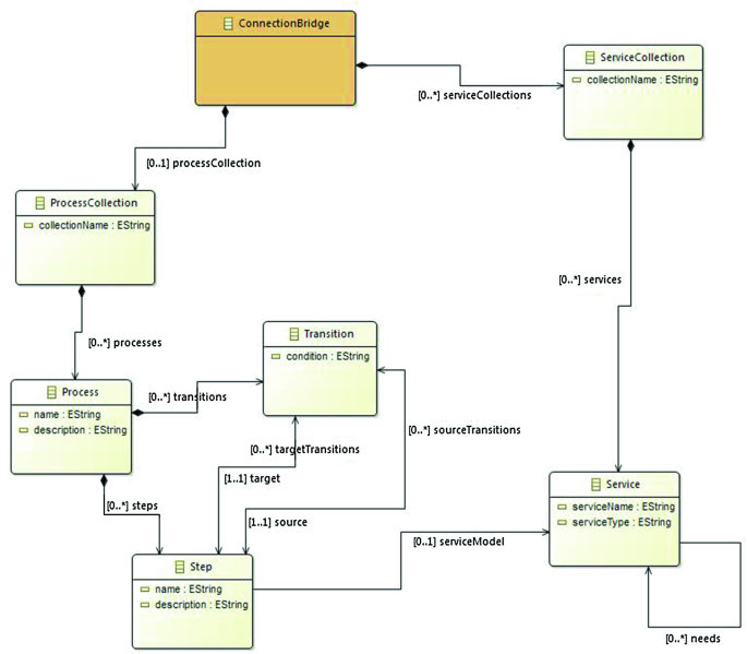
Inter-Layer Connection Bridge metamodel.
-
2.
additional semantic information that aid in inferring new facts,
-
3.
a representation of the different layers presented earlier in this paper and a corresponding mechanism to manipulate the objects in the SRS space accordingly.

In the remaining part of this paper, OWL2 [5] and SWRL [6] will be used as modelling languages, with the corresponding terminology. However, other formalisms could also be used as long as they allow the operations described below.
3.1 From the Inter-Layer Connection Bridge Metamodel to a Semantic Model
The data manipulated in the ILCB layer are modelled based on the ILCB metamodel presented in Fig. 3. Please note that the ILCB metamodel pictured here is only an example of what could be used. We have experimented with such models and there is some variety in them based on different needs, but the main elements required for the contribution of this paper are always the same. The metamodel itself is not a contribution that we claim for this paper, rather its existence is a prerequisite (easily achieved). In fact for this work we have experimented with a version of such a metamodel from the Eclipse MangroveFootnote 1 project. The ILCB metamodel is transformed into a semantic model in this step. This includes the UML classes, associations, attributes, and cardinality constraints presented in Fig. 3. Taking as an example OWL2 the following transformations are carried out:
-
the UML classes Step, Transition and Process are modelled as classes in OWL2,
-
the directed associations steps, transitions, targetTransitions, sourceTransitions, target, and source are modelled as object properties, having as domains and ranges the corresponding classes,
-
the attributes name and description are transformed in datatype properties,
-
we model constraints on cardinality 0…* as standard object properties in OWL2. The cardinality constraint 0..1 is modelled as a functional property (object or datatype one according to whether it is a relation or attribute in the UML diagram). For the cardinality constraint 1..1 we use maxCardinality with the limitations explained in [7].
Figure 4 includes a visual representation of a part of the resulting semantic model.

Part of the semantic model.
3.2 Enrichment of the Semantic Model
The semantic model allows us to perform semantics-based inference that was not possible only with the ILCB metamodel. We therefore assume that in addition to the information available from ILCB, other definitions can be inserted in the SRS component (it makes sense here to allow only users with appropriate profiles/rights to be able to add such definitions). For example, the temporal ordering of tasks can be represented in terms of binary predicates between subsequent tasks. In that case the expression.
could mean that Task1 has to take place before Task2 (an example would be the constraint that all payment operations must be done after processing invoices corresponding to the operation). The binary predicate before in the above example could have more semantic properties attached to it, such as transitivity, which could be used by a reasoning engine to infer additional information. Of course, the possible expressivity and inference power would be related to the chosen formalism adopted for implementing the semantic model.
3.3 Representation of the Business Process Modelling Layers in the Semantic Model
As presented in the previous sections, there are different modelling layers in the “non-semantic” space of our system. To keep the provenance of the objects (in terms of the layer in which they originated) in the semantic space, the notion of context is introduced. Each layer is represented as a separate context, that we will call local context, in the semantic space. For example, to assert that S1 has as a source transition T1 in the context CON, we denote that.
All local contexts are disjoint with each other. The SR dataset is then a union of the information that is in all local contexts plus a context that we will call global context and has the role of a transcending space, meaning that objects that are in different local contexts can also belong to the global context. We will call the operation of mirroring an object that belongs to a local context to the global one, lifting. When lifting an object we have to perform the following operations: first create a new object, link the initial object and the new one via a predicate (mapsTo) that preserves provenance, and place the new object in the global context. The last two operations could for example be performed via the following rule:
Binary (or n-ary if the formalism allows such a representation) predicates can also be lifted but in that case at least two of the objects that participate to the relation should also be lifted.
We have to note here that we allow objects to be lifted only if they are also represented in the ILCB metamodel (as they are the ones that can transcend contexts by design) or if they are added in the semantic space as explained in the previous section.
3.4 Coupling the Semantic Representation System with the Global Architecture
We consider two distinct possibilities with different pros and cons. The first one requires strong interaction between the SRS and the components that modify the models. Typically, such components are “SRS aware” and use an API to exchange information with the SRS, so that the SRS can update its internal representation in a consistent way, and/or react directly to any problems potentially induced by components.
The other possibility is a weak coupling, where the SRS analyses the products of model transformations (typically data structures encoded according to dedicated formats such as XML), and extract change descriptions or analysis reports by using dedicated algorithms. The interest here would be having weaker assumption about the compatibility of plugins, hence minimizing the impact on existing components.
Both approaches can be combined and chosen in accordance with the applicative domain relevance.
4 Query and Reporting System
The SRS maintains an RDF store and an OWL representation of the semantic model instance. It can be queried using standard technologies (e.g. SPARQL) and its consistency can also be verified by existing inference engines. Dedicated properties (depending on the applicative models) can be elaborated and checked through specific inference mechanisms or queries. The QRS can then be used as the backend for powerful business process workbenches where various users can launch queries pertaining to their own domains of expertise.
5 Illustrative Example
In this section we illustrate the steps described above with an example.
As a first step we transform the sample travel process, from the platform-independent form to the semantic form. Figure 5 (generated with Protégé 4.2 [8]) includes an example of that with the step Notify of information. As shown, the step “Notify of information” is transformed in an instance of the class Steps in the SRS space. The corresponding transitions are also transformed into instances (of a class called Transitions that is not shown here) and each transition is linked with the step instance through corresponding OWL2 object properties (i.e. sourceTransitions and targetTransitions in Fig. 5). It is important to note here that the local context to which this information belongs is also represented by the isInContext object property.

Example transformation of a Step from platform-independent to semantic space representation
As a second step in the we decide to add the following semantic relations to represent the ordering of the steps in the semantic model:
-
directlyBefore - to represent when a step is directly before another one in the sequence,
-
directlyAfter– the inverse of directlyBefore, represented as the triple (directlyAfter, inverseOf, directlyBefore) in the SRS space,
-
before – to represent when a step is before another step. This property is defined as transitive. Every directlyBefore property is actually a specialized before property denoted in the SRS space as (directlyBefore, subPropertyOf, before),
-
after – the inverse of before, represented as (after, inverseOf, before) in the SRS space. This property is transitive. Every directlyAfter property is actually a specialized after property denoted in the SRS space as (directlyAfter, subPropertyOf, after). When two steps are linked with a before property they cannot also be linked with an after property, defined in the SRS space as (before, disjointWith, after),
-
inParallel - denotes that two steps are taking place in parallel. For the purpose of our example we will say that when two steps are linked with the before or after properties they cannot be also linked with the inParallel property. This is defined in the SRS space as (inParallel, disjointWith, before) and (inParallel, disjointWith, after).
To infer when the semantic relations defined above hold between two steps in the SRS space we define a rule, in this case as follows (we use the SWRL formalism):
which in relation to the transformation done above help us infer that in our example:
Based on the definitions of the relations we have introduced above we can also infer that Notify_of_information_Mang_1 is before the Review request step and after the Check Address step, as shown in Figs. 5 and 6, in addition to other semantic relations (inference done with Hermit [9] in this case and visualized with Protégé).

Automatic explanation of inference leading to fact “Notify of information step is after the Check Address step”
In the third step of the process we define which individuals and subsequent relations we want to lift. Assume that we lift the first and second Notify of information steps in the DSL part, the Dispatch to organization and Check Address steps, and that we also lift the predicates that link them (namely (Notify_of_Information_1_DSL, directlyBefore, Notify_of_Information_2_DSL)). Then we have instances created in the global context that are linked through mapsTo predicates to the corresponding ones in the DSL context. Using the same inference rules as before, we also have in the global context information inferred, as shown in Fig. 7.

Inferred information for the first Notify of information step in the global context (before, directlyBefore, after predicates)
As explained in the previous sections, the different contexts are kept separate until a user with appropriate rights decides that he wants to lift to the global context specific parts of the information.
At this point in our example, we know that, because of the information lifted from the DSL local context to the global context, Notify of information 1 is before Notify of information 2 in the global context.
Assume that a user that operates in the BPMN domain specific layer then decides to modify the relation between the two tasks in the BPMN context, denoting that they actually happen inParallel. If the elements of the BPMN model are then lifted to the global context an inconsistency will be detected. That is because the information coming from the DSL context has asserted that Notify of information 1 is before the Notify of information 2 step while the information coming from the BPMN context asserts that the same two steps are inParallelFootnote 2. However, the predicates directlyBefore and inParallel have been defined as disjoint beforehand. Figure 8 illustrates the inference process leading to an inconsistency.

Inconsistency detected in the global context based on information coming from two different local contexts
The example above illustrates how the global context can help us keep a consistent state across different layers. This can be very useful when powerful business process graphical editors are used because it would simplify automatic validations (with errors shown on the graphical model).
6 Related Work
In [10] a mapping of BPM notations into OWL ontologies is presented. The purpose as explained by authors (see below) is to gain some semantic capabilities:
“Today, BP editor tools support modelers in building correct diagrams only from the syntactic point of view. Enriching them with ontologies may bring many advantages, that go from the possibility of applying advanced reasoning techniques, aimed at the identification of contradictions and mistakes in the model specification, to the possibility of organizing BP models repositories, with advanced search and retrieval facilities”.
However, the key idea of dealing with the various knowledge levels and associated languages is not addressed (hence, considering an OWL-based solution to deliver semantic interoperability, is not considered).
The so called semantic federation is another big trend where RDF-based ontologies are expected to play a key role [11]. Here, the interoperability problem is focused on building a common semantic representation of heterogeneous data objects (which were represented differently ab initio). Again, this significantly differs from our idea, which focuses on harmonizing different representations of semantically similar objects (those differences being the consequences of technical artefacts and possibly uncontrolled/decoupled evolution processes).
Another, less related trend is organized around translating BPEL definitions into OWL-S ontology, to foster compositionality of business processes [12]. The OWL-S ontology (see [13], not officially endorsed by W3C) was a proposition to facilitate the combination of services based on a semantically rich description of operations.
Some works focused on providing a more precise and explicit semantics through a “pure” translation of BPMN graphical representation into dedicated OWL ontologies [14] (this is roughly an attempt of bringing some operational semantics to syntactic representation). Again, the goal here is not to build some semantic interoperability between heterogeneous representations, but rather to describe one semantic applicable to all BPMN business process descriptions [14].
In [15], the authors present an ontology that models artefacts of the Oracle Business Process Management Suite. The ontology enables them to discover implicit relationships in data and find implicit and explicit relationships with pattern matching queries. However, they do not deal with different modelling layers as is our case. Crucially, they do not take into account domain-specific process models, which is key to our approach since we want to keep domain-knowledge in sync with generic BPMN and other notations (including SOA-related). In addition, they do not present a general methodology for transformation of diverse modelling artefacts in semantically coherent objects.
7 Conclusion and Future Work
In this work we have presented an approach towards the management of heterogeneous process collections containing business processes that correspond to various practices and domains, a challenge that large organizations face today.
More specifically, we believe that this work contributes an essential step towards the systematic management of business artefacts (domain-specific concepts, domain processes and BPMN) which are at the core of our vision for BPM. It does so by introducing a unified semantic layer (and hence inference capabilities) on top of domain-specific concepts as well as external concepts inherent to BPMN-based tools, which intrinsically do not allow this kind of principled representation. We envisage that such an approach will provide the foundation for novel search capabilities as well as consistency checks across the organisation’s business processes, in ways that could not be achieved with current approaches without laborious and ad hoc human work, not scalable at the enterprise level. An illustrative example was provided that demonstrated the applicability of our approach.
Semantic-based management of business process artefacts should eventually enable to manage and qualify business processes for consistency at the enterprise level. Corresponding searchable repositories of business artefacts would provide up-to-date view of the organisation’s business processes to all concerned stakeholders.
Actually, we consider this work as the initial foundational brick that will enable further advances towards broader business architecture governance, as we anticipate that the semantic mechanisms introduced here can be further enriched, in order, for instance, to embed semantic bridges towards the IT layer (hence enabling search and inference mechanisms not restricted to business concepts but involving business concepts and IT capabilities altogether). Another path towards reinforcing the governance capabilities based on this approach would consist in enriching the proposed inter-layer connection bridge with execution information so as to consider evolutions in the overall business description enabled by this work.
Notes
- 1.
- 2.
It is important to note that the mapping of the two instances coming from different local contexts to the same instance in the global context is achieved through the ILCB layer that has this information.
References
Mos, A.: Domain specific monitoring of business processes using concept probes. In: Toumani, F., et al. (eds.) ICSOC 2014. LNCS, vol. 8954. Springer, Heidelberg (2014)
Suri, K., Mos, A. Human task monitoring and contextual analysis for domain specific business processes. In: International Conference on Software & System Engineering (ICSSEA 15), Paris, France, 27–29 May 2015
Object Management Group, Business Process Model and Notation. http://www.bpmn.org/
Mos, A., Jacquin, T.: Improving process robustness through domain-specific model transformations. In: Enterprise Distributed Object Computing Conference Workshops (EDOCW 2013), Vancouver, BC (2013)
W3C (OWL Working Group).: OWL 2 Web Ontology Language Structural Specification and Functional-Style Syntax. W3C Recommendation, 27 October 2009. http://www.w3.org/TR/owl2-syntax/
Horrocks, I., Patel-Schneider, P., Boley, H., Tabet, S., Grosof, B., Dean. M.: SWRL: A semantic web rule language combining OWL and RuleML. W3C Member Submission, 21 May 2004. http://www.w3.org/Submission/SWRL/
Zedlitz, J., Jörke, J., Luttenberger, N.: From UML to OWL 2. In: Lukose, D., Ahmad, A.R., Suliman, A. (eds.) KTW 2011. CCIS, vol. 295, pp. 154–163. Springer, Heidelberg (2012)
Stanford center for biomedical informatics research, 2013. Protégé Project, May 7, 2015, from Protégé: http://protege.stanford.edu
Shearer, R., Motik, B., Horrocks, I.: HermiT: A highly-efficient OWL reasoner. In: Ruttenberg, A., Sattler, U., Dolbear, C. (eds.), Proceedings 5th International Workshop on OWL: Experiences and Directions (OWLED 2008 EU), Karlsruhe, Germany, October 26–27 (2008)
Lezoche, M., De Nicola, A., Di Mascio, T., Taglino, F.: Semantic lifting of business process models. In: Workshops Proceedings of 12th International IEEE Enterprise Distributed Object Computing Conference (EDOCW 2008), Munich, Germany, 16 September (2008)
Aletheia project consortium. Aletheia – semantic federation of comprehensive product information (2010). http://www.aletheia-projekt.de/
Aslam, M.A., Auer, S., Shen, J., Herrmann, M.: Expressing business process models as OWL-S ontologies. In: Eder, J., Dustdar, S. (eds.) BPM Workshops 2006. LNCS, vol. 4103, pp. 400–415. Springer, Heidelberg (2006)
OWL-S: semantic markup for web services. W3C Member submission November 2004. http://www.w3.org/Submission/OWL-S
Rospocher, M., Ghidini, C., Serafini, L.: An ontology for the business process modelling notation. In: Proceedings 8th International Conference on Formal Ontology in Information Systems (FOIS2014) September, 22–25, 2014, vol. 267, pp. 133–146. IOS Press, Rio de Janeiro, Brazil (2014)
Prater, J., Mueller, R., Beauregard, B.: An ontological approach to oracle BPM. In: Pan, J.Z., Chen, H., Kim, H.-G., Li, J., Wu, Z., Horrocks, I., Mizoguchi, R., Wu, Z. (eds.) JIST 2011. LNCS, vol. 7185, pp. 402–410. Springer, Heidelberg (2012)
Author information
Authors and Affiliations
Corresponding author
Editor information
Editors and Affiliations
Rights and permissions
Copyright information
© 2015 Springer International Publishing Switzerland
About this paper
Cite this paper
Lagos, N., Mos, A., Vion-Dury, JY., Chanod, JP. (2015). Preserving Consistency in Domain-Specific Business Processes Through Semantic Representation of Artefacts. In: Abramowicz, W. (eds) Business Information Systems Workshops. BIS 2015. Lecture Notes in Business Information Processing, vol 228. Springer, Cham. https://doi.org/10.1007/978-3-319-26762-3_4
Download citation
DOI: https://doi.org/10.1007/978-3-319-26762-3_4
Published:
Publisher Name: Springer, Cham
Print ISBN: 978-3-319-26761-6
Online ISBN: 978-3-319-26762-3
eBook Packages: Computer ScienceComputer Science (R0)