
Abstract
Nature has developed solutions for itself over time through complex networks. This strategy can be confirmed as successful in comparison to more technical, “linear” optimizations. On the contrary, natural optimization succeeds through reproduction, mutation, recombination, and selection, as well as the use of failures as a means of improvement.
Access provided by Autonomous University of Puebla. Download chapter PDF
Keywords
These keywords were added by machine and not by the authors. This process is experimental and the keywords may be updated as the learning algorithm improves.
Nature has developed solutions for itself over time through complex networks. This strategy can be confirmed as successful in comparison to more technical, “linear” optimizations. On the contrary, natural optimization succeeds through reproduction, mutation, recombination, and selection, as well as the use of failures as a means of improvement.
The examples of biomimetics in this chapter cover realized examples as well as studies and idea sketches. The biomimetic method of abstracting a biological example for technological usage should be comprehensible and replicable. The examples in this book can never definitively show the possibilities of biomimetics and are considered more as stimulae and inspiration for one’s own work.
It has become recognized that biomimetics is to be understood as a tool, as a resource, one that can stand alongside other classical design and development tools. To architects, planners, builders, and designers it will depend on obtaining an optimal result. Whether one uses only one method or combines multiple methods is for the end product the same. “Purely biomimetic” results will be shown in the following paragraphs, as well as results that merely represent analogous developments in technology and nature and do not follow the pure definition of a biomimetic process.
Above all we are convinced that the world of architecture is too complex and therefore no “biomimetic architecture” can theoretically exist. However, individual construction elements and materials or functions from nature can be interpreted in technology. A complex building consists of many elements, spaces, and functions that arose from a background of norms, traditions, and technological requirements. The German VDI guideline 6220 and the VDI guideline 6226 for the area of construction have already specified that a product can be only defined as biomimetic if its essential elements are developed biomimetically. Therefore a term like “biomimetic building” is clearly not consistent. We refuse the question as to whether or not a “biomimetic building” can exist, despite the debate of whether this or that building is biomimetic being present in varying publications. The term is often only used as a marketing strategy or arises from a general misunderstanding. Small structures, for example pavilions, can be accepted as exceptions to the principle that no true biomimetic building exists. Such examples will also be introduced in the following pages. Therefore, the limits of biomimetics are not to be misunderstood: We are convinced that biomimetics has its place and is due to achieve a prominent meaning through the use of development potentials.
Biomimetics is justifiably depicted as a cross-section of disciplines, which will become clear in the following examples. Scientists often work beyond their subject area of knowledge, leading to expedient combinations of technological developments and biomimetic inspirations. Biomimetics is in many cases an integrative working tool.
In summary, the reader should be able to obtain with the help of the following examples an impression of the possibilities and depth of biomimetic approaches to design and be inspired to one’s own ideas. The reader should also recognize where parallel developments on a technological foundation have already led to success without nature having had stood by as direct mentor.
The chapter begins in the first subsections with an extensive, though not all-encompassing, recount of the course of biomimetics research, showing possible development tracks through history and then discussing the results. The descriptions are kept relatively comprehensive, so that the research depth necessary for biomimetics is recognizable. However, despite the comprehensiveness of the descriptions they cannot entirely depict the scope of research, as they would overstep the possibilities within this book. In relation to the research examples, various exemplary developments and ideas in biomimetics will also be introduced, each limited to two pages of each subsection to simplify the comparison to one another. These sections begin with the biological precedent, clarifying the process of abstraction to technological realization and the possibility of utilization. The analogous developments of technology and their biological functioning counterparts will each be shown in the same manner. Further information about the authors, photography credits, and addresses for further research about the given examples are gathered in the end credits.
6.1 Biomimetics on the Basis of Algae, a Biological Example
Algae serve as the source of nutrition for many ocean dwellers and represent among other forms of life the lowest level of the food chain. Discolorations found in ocean water known as algal blooms are a well-known effect of this organism. Lesser known is that the single-celled algae are co-responsible for atmospheric carbon dioxide production on Earth, playing a larger role than the rain forests, for instance. The number of single-celled organisms in our oceans is compared with the number of celestial bodies in the universe and is estimated at 10²². The pigment composition responsible for the coloration of the oceans is less interesting for biomimetics as are the microscopic and extremely manifold construction of the algae themselves. The fine structure of the exoskeleton and its abutting plasma layer separates the cell contents from the ocean water .

Fossil marine diatoms from the Oamaru-Deposit in New Zealand (late Eocene), arranged by Alfred Elger, circle diameter ca. 500 µm
These skeleton-like structures are built up through the use of different structural principles and various materials: coccolithophores use calcium carbonate (CaCO3); diatoms, radiolaria, silicoflagellates use silicates (SiO2*n H2O). Complex geometric structures are built by Foraminifera through the use of calcium carbonate, by Acantharia through the use of celestine (SrSO4), and by Radiolaria, also with the use of silicate. The diatoms form the largest group with approximately 25% of the total. The shells of the diatoms have developed a highly geometrical complexity (Fig. 6.2), upon which the individual types differentiate themselves, the number of which is projected at 100,000. Their rib, honeycomb, and pore structures have sizes of about 1 µm, 150 nm, and 20 nm and shape the body mass into a triangular, cylindrical, needle-like, or into other further geometries, in often fractal, self-repeating structures. Many prominent scientific investigations are currently underway, which is important also for the further research in biomimetics.

Typical representative of the diatoms with clearly visible petri dish form: Actinoptychus
The discovery of the attractive forms of the microscopic diatoms and radiolaria (Fig. 6.1) led to their use in academic salons in the nineteenth century, where educated society was able to view the preserved specimens in microscopes and philosophize about the beauties of nature (Fig. 6.1). Around this time the widely read, although today antiquated work of Jena Biologist Ernst Haeckel appeared: “Art Forms in Nature.” In the 1970s and 1980s academics such as architect Frei Otto , known for his light, tent-like structures, botanist Johann-Gerhard Helmcke, and plant physiologist Anne-Marie Schmid further analyzed the origins of the forms of diatom husks (Fig. 6.3).

Different exterior forms and symmetry relationships of diatoms
In the meantime, knowledge of this subject was able to be refined and exacted. Present-day scientific insights have shown that the shell structures of diatoms fulfill the high demands of static stability and mechanical load-bearing capacity. Furthermore, the shells are optimized against attacks from Copepods (Copepoda) and their silicate-coated oral apparatuses. For protection, the diatoms use a hard, though delicate, shell of bio-silicate that is so finely structured that the smallest pores in the silicate hull occupy the same semipermeable characteristics as a membrane: Certain particles of matter are allowed into the cell body, whereas others are excluded.
6.2 Pool Research as Biomimetic Method in Application
The shell formations of diatoms are ideally suited as subjects of investigation for lightweight constructions, a subject that G.P. has concerned himself with for years .
The informational and investigational material of G.P. at the Alfred-Wegener-Institute in Bremerhaven from the research activity by PlanktonTech is available here. In the frame of the international research project PlanktonTech, a virtual institute of the German scientific Helmholtz Society, biologists occupy themselves with the basis research on plankton as well as architects and engineers with the question of technological feasibility of products in the areas of architecture and design. With the biomimetic method “Pool Research” scientific insights were collected, evaluated, and supplied to the direct prototypes from the research series PlanktonTech (compare: COCOON_FS, introduced in another chapter of this book) and made available to the industrial wood construction development within the framework of BOWOOSS (BOWOOSS is a biomimetics research project on the use of shells in wood construction).

Construction schema of a diatom shell
6.3 Pool Research: Abstraction Through the Classification of Biological Precedents
6.3.1 Classification of Diatom Species
Diatoms consist of two interlocking shells, the hypotheca and the larger epitheca, that surround the smaller hypotheca. The shells link together in the connective region, known as the girdle band, to form a larger mass known as the valve (Fig. 6.4).
The focus of the classification of diatom types led by research project BOWOOSS rested on the investigation of particularly outstanding examples (Fig. 6.5), which were considered to have particular application for the construction industry. With the help of this classification, the researchers were able to successfully isolate and compare different solutions in nature with structural problems.

Extract of classification of diatoms
The foundational organizational shapes were divided into categories based on radial or ctenoid appearance, according to Round et al. This division appears insufficient in light of the present knowledge; as a supplement to those categories diatoms with perforation are also included (Fig. 6.6) .

Fundamental forms of diatoms
The classification relates overwhelmingly to morphological and topological characteristics of the valve, because for some the girdle bands are often only fragmentarily or not at all present (something that admits inferences to the stability of the connection), and for others the structural constitution of the girdle bands is considered as relatively modest. Correspondingly, the taxonomic ordering is most successful when based on the observations of the valves (Fig. 6.5).
The large variety of types of living and fossilized diatoms (estimates range from 10,000 to 150,000, compare: IL 28 S. 42) and the consequent variety of shapes and structures could be suitable for wide-ranging approaches for their interpretation in architecture.
6.4 Pool Research: Analysis and Evaluation
The ability to analyze the morphological construction of diatoms lies in the observation of their shell structures (Fig. 6.6). In related investigations, distinctive features have been recognized for their similarities to structural members of architecture .
Hierarchical Ordering of Members
Diatom shells consist of several differently scaled structures connected with one another. The hierarchical ordering (Fig. 6.7) of these structures is an essential noteworthy aspect in the shell structural system. This term depicts the dissolution of a load-bearing structure to a system of individual elements that are in turn always further subdivided into a substructure. This subdivision often follows a diminishing, self-repeating pattern. The corresponding increase of surface moment of inertia and the reduction of weight and material usage can be considered efficient when compared with “monolithic” structures. Often closed, honeycomb-structured cavities called “bullulae” (i.e., in Aulacodiscus) are encountered, which produce a foam-like substance (compare: II 28 DIATOMEEN I, p. 56). Also to be found are spherical pockets and two-dimensional mesh networks (IL 28, p. 80).

Isthmia
Strengthening Ribs
Many diatoms, in particular those belonging to the type Pennales, exhibit on the underside of the valve a pronounced rib structure, often consisting of a parallel or radial system, to which the lesser members are connected. Reinforcement on the outer edge is present in virtually all types in order to absorb tension forces on the shell (i.e., Figure 6.8 Arachnoidiscus) .

Arachnoidiscus
Symmetry
Equally striking is the observed symmetry in the specimens. The Centrales consists of a radially symmetric structural system of mostly round or polygonal shells. As opposed to the pattern of Pennales the substructure of Araphidineae has a pronounced dual-axis symmetry.
Separated Shells
In many types (i.e., Actinoptychus Figs. 6.9, 6.10, 6.11) it is to be noted that their shells are constructed from two morphological and completely differentiated layers, whose structures seemingly bear no relationship to one another (compare: IL 38. DIATOMEEN II, p. 90 ff.).

Actinoptychus

Actinoptychus

Actinoptychus
Parallels to Architecture
The similarity to architectural construction is particularly noticeable in centrally chambered diatoms. The individual elements of the shell, namely the outer boundary layer, the lateral boundary layer, and their interstitial connecting members, can be easily compared with the architectural terms overtruss, web, and undertruss. Similarities with double-layered frameworks are obvious (IL 28, p. 288 ff.) in more decomposed shells. The rib structures can also find a counterpart in architecture. The comparison is most clear in Arachnoidiscus, whose shell recalls a cement-ribbed vault, thanks to meridial ribs and sublayered concentric ribs .
6.5 Pool Research: Abstraction of Geometric Principles
The significance of exploring more complex geometries of morphological building methods lies upon the notion that avoidance of geometric complexity in technological developments has up to now been the rule. However, complex structures of biological systems have already proven a superior performance .
These types of structures require developments in support systems, connections, and overall complex production and assembly chains for the supply of building parts to be used for architecture . The further investigations of diatoms within the framework of BOWOOSS and the translation of the developed forms into computer-aided design (CAD) models require an abstraction of the discovered principles. In light of their symmetrical characteristics, the simple constructions of the Centrales and the Pennales appear to be especially advantageous for the task of abstraction and translation into architectural forms (Fig. 6.12).

Organism and abstraction
6.6 Pool Research: Translation into CAD Models
In the later stages of the research project BOWOOSS the first translated patterns were investigated to verify the suitability for later implementation. In the first instance, potentials were sought that could be realized in wood construction. The interpretation of the three-dimensional (3D) models, though within the limits of CAD’s “drawability,” yielded recognizable forms that could already be discerned for their use for later production .
6.6.1 Structuring of a Free-Form Surface Analogous to the Centrales
For this CAD model a regular, repeating hexagonal structure following the precedent of the diatom was applied to a free-form surface. The orientation of members follows a polar coordinate system, which lead however to a heavy distortion in the polar region, affecting the breadth of the struts (Fig. 6.13).

Models of geometric abstractions
6.6.2 Structuring of Free-Form Surface Analogous to the Diatom Species Craspedodiscus
The basic form of this CAD model is a completely asymmetrical, double-contorted free-form surface. The structure is inspired by the spiral-patterned openings of Craspedodiscus; similar patterns can be found on the flower heads of sunflowers (Fig. 6.14).

Models of spiral abstractions
6.6.3 Segmented, Radially Symmetric, Double-Contorted Free-Form Surface
By structuring this surface with a concentric pattern many meridial members meet together in a center, resulting in an unrealistic “fusion” of members at the intersecting point. This problem could be evaded by a tapering of these members, but high costs would be expected for a constructable implementation (Fig. 6.15) .

Models of radially symmetric, segmented abstraction
6.6.4 Structuring of a Free-Form Surface Analogous to the Pennales (Araphidineae)
A right angle-derived, dual-axis symmetrical free-form surface, whose direction of curvature differs along the length of the surface, was used as the basis for the following variants. The CAD models were processed for calculation and optimization with the FEM Program SOFiSTiK. The size of the building members and the thickness of the structure were assumed to be for a comparatively small structure (Figs. 6.16, 6.17).

Abstracted free-form surface analogous to the Pennales Araphidinae

1–8 Models for free form surface abstractions. 1 Rhombus-shaped lattice, oriented on internal surface coordinates. 2 Arch construction with diagonal bracing. 3 Projection of a regular rhombus-shaped lattice in plan view. 4 Like 3 with additional arches along the sectional axis. 5 Regular orthogonal lattice along the uv-coordinates. 6 Hexagonal pattern along the uv-coordinates. 7 Projection of a concentric pattern in plan view. 8 Orientation of a concentric pattern along the uv-coordinates
The high demands on the manufacturing and engineering of these components are already obvious with these first, simple computer models, even without the inclusion of assembly details. Even if these models were to be divided into individual elements for production, each element would still be curved along the two axes. Such building elements could only possibly be prepared with the means of a costly 5-Axis CNC mill (Fig. 6.16).
6.6.5 Evaluation
Nature as structural precedent can be modeled with the means of CAD programs, but in reality this method ensures that the developed geometries can be constructed only through the use of complicated methods. For example, the radially symmetric models, whose meridial members meet at a central point, could only be realized as load-bearing elements if they behaved similar to nature, that is, tapering or fusing together. The common technological practice of producing prefabricated parts and assembling them in construction reaches its limit. More advantageous would be freely formable, literally growing structures. The synthesized abstraction efforts for free-form surfaces (Fig. 6.17) based on the analysis of diatom structures only illustrate the "directly" translated ideas .
6.7 From Pool Research to Applied Research
Data Processing for Analysis and Construction
The insights supplied from the Pool Research at this stage could have been further developed on various different tracks; however, in this case the focus lies on the utilization of the data for a CAD–CAM (computer-aided manufacturing) process. The processing of the data by the FEM program (SOFiSTiK) runs parallel to its construction in the DXF or IGES format. The translating process was prepared for eventual CNC-driven fabrication (Fig. 6.18) .

Process scheme of data preparation for analysis and construction
6.8 Generative Design
The technical possibilities offered by computers and software increasingly influence architectural design. With the means of generative design, a CAD process can use the capabilities of modern data manipulation. Parameters describe functional or geometric contexts or requirements and connect the specifications together in such a way to aid the user with design decisions; simply stated, a linking of design, mathematics, construction, and also function. Therein lies the ability to quickly consider and experiment with many iterative variations of development; the number of which depends only on what the user considers to be a sufficiently executed study. As a rule, parametric design tools are used to find optimal solutions or to weigh different design variations. However, these instruments of generative design are not only implemented in the design and concept process, but have also found usefulness in later planning phases, for the visualization of different conditions, and successions of different variations. The parametric descriptions allow a high variability within the dependencies of the given conditions, in which nearly limitless possibilities are generated. For example, path routes can be simulated, spatial confinements described (i.e., building gaps or building space), or static, use-conditioned (necessary free openings, passage ways, etc.), as well as zoning requirements integrated with each other, serving as a "specification guide" for the project model. Further capabilities could be considering various load-bearing systems for a structure, observing different effects of daylight and building transparency, or comparing facade designs and skins (Figs. 6.19, 6.20, 6.21).

Inzell speed skating hall

Inzell speed skating hall: typical study of daylight intensities

Inzell speed skating hall: typical study of rainwater flow
For the recently constructed speed skating venue in Inzell (Figs. 6.19, 6.20, 6.21) the project team of Behnisch–Pohl Architects developed a large, cantilevered roof form with the use of generative programming and, in cooperation with lighting specialists from Bartenbach Lighting Lab and climate engineers from Transsolar, were able to optimize daylight penetration and indoor climate.
A further example of the use of generative design tools is the competition project for a new convention center and neighboring train station in Luxembourg (Figs. 6.22, 6.23). Pohl Architects parametrically programmed 3D iterations to weigh different functional optimizations and design appearances, whose process is described next.

Convention center train station in Luxembourg, parametric model of column placement relating to transportation surfaces

3D model of Luxembourg convention center and convention center station
Parametric 3D Design for the Development of Constructional Principles
The roof support system for the exhibition hall of the convention center in Luxembourg is based on a 6 m raster, which could be adapted to the grid pattern of the entire complex as well as to grid of the roof envelope itself. This envelope and its geometric formation had to support the overall design concept of “Solar Plus” pertaining to solar energy production for the complex. Its folded form is a result of the exploration of specific parameters (Fig. 6.24, 6.25), so that the roof surfaces with embedded solar panels are placed at the optimal angle with respect to the Sun; at the same time enabling the opposite, skyward surfaces to allow the most glare-free, indirect light into the interior. The multifunctional folding shape functions equally as part of the structural system while retaining geometric developability and regularity, so that the outer sealing could be economically implemented and with a high degree of prefabrication. The parametric optimizations defined the final dimensions and slopes of the folds and their basic configuration, owing in part to the fold principles of Japanese engineer Miura. The transition from the horizontal roof to the vertical facades was likewise parametrically modeled and developed in 3D (Fig. 6.25).

Luxembourg convention center, parametric programming of the envelope

Luxembourg convention center, parametric development process for the envelope folds
An undulating facade for the envelope of a planned high-rise structure as part of the convention complex was also determined using parametric constraints. With the capabilities of the parametric tools, the designers could achieve a unique, shifting facade despite demands of structural loads and the economic feasibility of reproducibility and fabrication. The entire building volume was reshaped by these rigorous constraints.
Parallel to the convention center building construction, the user requirements of the neighboring train station, that is, track beds, train platforms, escalators, and footbridges, needed to be mapped and modeled as well, in order to find possible positions for vertical supports for an efficient structural system (Fig. 6.22). In this manner tree-like branching columns under a crinkled roof landscape were designed, which despite their regular placement managed to correspond with the irregularity of the interior activity and the form of the roof itself.
6.9 Physical Models
Following the technical experiments, simple methods were imagined for the realization of biomimetic constructions through the means of physical modeling and without the aid of computer technology, that is, drawing materials, cardboard, scissors, and glue. Contrary to computer models, whose graphic visualization only simulates structure, physical models give immediate feedback to this property. The materials to be implemented for a future building often demand further constraints (i.e., material-immanent characteristics, accessibility, production and assembly costs, limitations and realities of transporting large elements, behavioral tendencies, durability, etc.); however, abstracted physical models are well suited for first approximations of these requirements (Fig. 6.26).

Simple modeling attempts of different forms and assemblies
The implementation of biomimetic discoveries into physical models was executed within the framework of a student workshop at the B2E3 Institute for Efficient Building at the School for Architecture in Saarbrücken, shown in these images. The students were tasked with the development of a skin structure for a small pavilion following a precedent in nature. They were to test biomimetic work methods and develop new creative potentials, while researching and abstracting inspirations from biology. Simple designs of physical, analogous structures were then drawn by hand and fleshed out in models of cardboard, wood, or fabric.
The accumulation of insights that underlies this process also suited for students is found in the discovery of “natural” solutions, without the background knowledge in technology. The biological examples offer recurring design stimulae, give clues to new methods, and are partners in the struggle for creative stimulation.
In the next step, the hand-drawn and modeled discoveries were translated into CAD models. The computer modeling simplified the process of building of complex, 3D physical models. The advantage of this step lies on being able to identify realistic and feasible proportions on the computer and then comparing and considering them with actual, physical models .
This potential of modern CAD systems for developing and testing prototypes was not available for Frei Otto’s early fabric and textile models of experimental tent constructions at the Institute for Lightweight Structures in Stuttgart: The modeled form was photogrammetrically displayed and replicated onto further modeling attempts up to the final 1:1 construction. The geometry revealed itself retroactively (6.27 c,d).
As shown in the student work at B2E3 Institute in Saarbrücken in Figs. 6.26 and 6.27a, b and 6.28 and 6.29, biomimetic-inspired building elements were developed for a wood skin. Their complex structures were worked out from simple cardboard models and hand drawings, as well as from intricate 3D CAD models, whose ability for complexity further intensified the designs (Figs. 6.27, 6.28, 6.29).

a–d (above to below) a and b (above): Working on simple physical models. c and d (below): Model by Frei Otto for an experimental structure at the Institute for Lightweight Structures at the University of Stuttgart

a–c (above to below) a (above): Model of bent paper strips for a free-form structure. b (below): Paper strip model of an irregularly woven, dome-shaped skin. c (below): Model of offset wood panels

a–d (above to below) a (above): Sclerenchyma of an Opuntia. b (above): Vein structure of a dragonfly wing. c and d (below): Implementation of a skin structure from the precedent of the dragonfly wing: paper model and computer model
6.10 Biomimetic Potentials: Ribs and Frames
The additional skin studies are based on the considerations of how a dynamic, flowing form could be produced from individual, planar pieces. Wood was chosen as a construction material. The form and structure recall a curved conch or snail shell.
Despite the twisted form, all rib members are able to be milled from wood panels and are simple to fasten together, as all of the ribs cross at right angles. The ribs in sectional direction are laid parallel to one another; in cross-section the ribs are laid radially around a middle axis. Because of this pattern, the rigidity against twisting is increased .
In architecture there is a series of examples for this type of construction process, though, as a rule, they are often built of ribs perpendicular to each other, as for example in the project “Metropol Parasol” in Sevilla by architect Jürgen Mayer H. In this example, a modeled volume was sliced with an even grid in plan view. With this so-called “egg slicer” method the fiber direction of the wood is often not taken into account, resulting in less correlation between structure and form (compare: Kraft and Schindler 2009. Digital carpentry in: Sabine Kraft et al. (pub.): ARCH + 193: Holz, September 2009, pp. 94–95.) (Figs. 6.30, 6.31, 6.32).

Cutout patterns

Biological precedent: Ribs and framework of Arachnoidiscus

Ribs and framework for a roof structure
6.11 Biomimetic Potentials: Rectangular Frames
The basic form for this construction is patterned according to tortoise shells, which are built up from two layers: the outer layer of scales and the underlying bone plate. The stability of the shell is reliant upon this layering (see: Westheide, W./Rieger, G. (pub.), 2010. Spezielle Zoologie. Teil 2: Wirbel-order Schädeltiere. Heidelberg: Spektrum, p. 365). For a constructable interpretation two or more layers of slotted, square frames were linked together to form a stable structure pattern, of which many variations could theoretically exist. Models of some different variations were tested in CAD and cardboard models. The patterns were able to range from nearly regular to chaotic systems. The structure consists of the same elements throughout; the variation lies in the changing positioning of slots that connect neighboring elements. The CAD models were generated partially with the help of "Paneling Tools": Because the panel connection slots intersect at complex angles, a 5-Axis CNC mill is necessary for production, as otherwise the production effort and cost would rise because of increased manual labor. The square frames are then mounted in complete assembly and connected by means of biscuit joints and screws (Figs. 6.33, 6.34, 6.35, 6.36).

Fragment built of similar square modules

Biological precedent: shell of a marsh turtle, left scales, and right underlying bone plate

a–d Application of the structures to a free-form surface

Dome-shaped shell of similar square modules
6.12 Biomimetic Potentials: Layered structures
This structure consists of a further development of the earlier described systems. The essential difference here lies in the pieces being bent perpendicular to the surface. The arrangement of the elements in two layers on top of one another allows the surface moment of inertia to be increased. Similarly, the pretensioning of the elements and the layering of two hexagonal grids heightens the stability of the system. For materiality, curvable strips of material, that is, plywood, were considered. The individual parts could be produced with minor expenditure with a 3-Axis CNC mill; however, the issue in this experiment is the application of the system to free-form surface, because each part is slightly different. Although it is possible to develop multi-curved parts—as represented in the following study—a manual assembly would prove to be too costly. An automatized scripting process would lend itself, in this instance, to designate the parts in a comprehensive manner, thereby preventing confusion during assembly. For the first considerations to this functioning paper model principle the connections are kept as simple as possible for implementation in small-scale models. The elements are fixed at the nodes with screw joints; the entire form then automatically conforms itself to the most efficient structural position, a particularly important step for curved surfaces. Only when the structure finds this position can it be glued together. The use of this structure for planar surfaces beyond architecture is imaginable, such as in the construction of layered flooring systems, vibration protection of HVAC systems, and soundproofing in sport complex (Figs. 6.37, 6.38).

Abstraction and model

Biological precedent: layered structures with regular geometries in Isthmia
6.13 Biomimetic Potential: Offset Beams
The study of offset beam constructions follows the precedent of Staurosirella diatoms. The first generated forms were made possible with the help of the Paneling Tool in Rhino. A 3D basis module is generated on a previously given free-form surface. With the input of a duplication with a certain factor (here four) and the establishment of the X- and Y-axes, an offset of the elements along the surface is possible. An earlier constructed parallel surface determines the depth ( Z-axis) of the basis elements and, in turn, the structure. A previously defined raster dimension (here points on the surface) determines the dimension of the grid. After several studies a particular variant was chosen to further investigate its structural capability and rigidity in model (Figs. 6.39, 6.40).

Offset beam structures in the diatom Staurosirella

a–f Offset surface structures are applied in a truss-like system—abstracted and e–f implemented in the model
6.14 Biomimetic Potentials: Incisions and Curvature
The precedent of the diatom species Synedrosphenia form the basis for the experiment sequence of bent planar elements. Similar to the other experiments, variously shaped modules were developed and generated on a determined model surface. Using the bent elements, a space defining structural system was created, whose load-bearing members mutually support one another. The surfaces can be constructed from plywood strips and acquire a structural stability with appropriate dimensioning and connections with the neighboring surfaces, as well as through the geometric curvature (Figs. 6.41, 6.42, 6.43, 6.44).

Forked structural system in the diatom Synedrosphenia

a and b (above, below) Model of abstraction of forked and bent surface-forming structural elements

3D model of a three-dimensional structural system from curved surface elements

a and b (below) Model in plywood
6.15 Biomimetic Potentials: Curvature
The subsequently described structure is based on the sclerenchyma skeleton of the Opuntia, a cactus species. This form is built principally from parallel longitudinal members connected to sinusoidally curved braces, formed from elastically deforming parts that can be held in position by the parallel elements. Particularly well-suited for the modeling of this form is birch plywood, which exhibits a strong rigidity in curvature. This building method is recognizable in many natural structures, notably in fibrous structures, which contain pressure-resistant cells between their tension-resistant fibers and form supporting “pillows” of fluid (Figs. 6.45, 6.46).

a and b Opuntia as precedent for curved elements: right, an intact stem; left, sclerenchyma skeleton

a–d Curved structural members. b Paper strip model. a, c, and d Modeled in computer on a free-form mass
6.16 Biomimetic Potentials: Hierarchical Structures
The diatom species Actinoptychus is well suited as a precedent for hierarchical structures. In this example, ever finer substructures (secondary and tertiary structures) diminish from a larger primary structure. In the biological precedent these structures, on the one hand, take on the role of separating the cell body from an outside medium (sea water), on the other hand the role of mechanical (protection against natural enemies) and static functions (general body structure). The bio-silicate used by the diatom is efficiently implemented and represents an astoundingly stabile framework with a complex spatial 3D structuring (Figs. 6.47, 6.48, 6.49, 6.50).

Hierarchical structuring of the diatom Actinoptychus

a and b Biological precedent. Abstracted above. Below 3D model of a roof support system with hierarchical construction, technologically interpreted from the abstracted precedent

Model of abstraction: hexagonal structures form support elements in a sandwich plate

Roof construction modeled in 3D with the use of hierarchical structures
6.17 Biomimetic Potentials: Fold Systems
Folding is a widespread principle found in nature for increasing the rigidity of surfaces. For example, folding structures are to be found in insect wings, tree leaves, and sea shells. Cactuses often have folded forms for, among other reasons, the increasing of surface area.
With the construction of free-form surfaces in a folding system, that is, the technological interpretation of biological precedents, a geometric problem presents itself, which naturally growing structures do not to need negotiate: the surface must be fragmented into planar shapes. The fragmentation of a surface with a regular pattern (tessellation) occurs without problem with the use of triangles, because a plane can always be constructed from three points in space. Various 3D formats are based on this principle. However with four-sided shapes the points do not automatically lie on a plane. With help from the plug-in “Paneling Tools” for the CAD software “Rhinoceros” it is possible to approximately describe a multi-curved surface with quadrangular planes.
The forming of the individual panels represents the next problem. The edges here would exhibit irregular angles to one other, shapes only technically producible with the aid of a 5-Axis CNC mill. This aspect and the building joints in general were disregarded in the subsequent models. The model in this instance merely describes the outer surface of the skin (Figs. 6.51, 6.52).

Foldings in leaves

a–e Paper strip models are able to be developed with the aid of triangle structures. The folded masses are more or less irregularly formed and consist of planar individual surfaces, thus easing a technical realization
6.18 Translation and Technological Implementation in the Example of the BOWOOSS Research Pavilion
Before the potential for biomimetic-inspired solutions can be tested in larger, complex systems, it is necessary to experiment with differently suited building elements in a smaller scale. Simple, single functioning spaces, similar to the first small-scale physical models, are qualified for this task, such as pavilions. These spaces serve the investigation of appropriate design tools and interfaces through the production, selection, and testing of materialities, as well as feedback to their preparation, transportation, and construction, and their overall capability. The test structure is an enterable and experiential ambassador for experimental construction.
The research project and the BOWOOSS Pavilion is a joint project under the funding guidelines of the German Ministry for Education and Research BMBF (Bundesministerium für Bildung und Forschung der Bundesrepublik Deutschland). The research emphasis of biomimetics was promoted by the national government as a high-tech strategy for sectoral drivers of innovation in environmental technologies under the title “BIONA—bionische Innovationen für nachhaltige Produkte and Technologien” (“Biomimetic Innovations for Sustainable Products and Technologies”). In this frame of research, within which the overlapping disciplines of biology, architecture, civil engineering, industrial design, various scientific disciplines of technology, including process engineering and optimization strategies, economic sciences, sociology and other research subjects all converged, renewable raw materials and lightweight constructions played a special role in the area of architecture. The focus on resource-saving building methods was highlighted in all submitted research projects as a special emphasis. Within this context, the subsequently described research project BOWOOSS investigates the subject matter of sustainable building systems of biomimetically inspired wood shell constructions.
6.18.1 The Research Project BOWOOSS as Example for Research and Development
The acronym BOWOOSS stands for “Bionic Optimized Wood Shells with Sustainability.”
The research project occupied itself with the implementing of insights from biomimetics for sustainable wood shell structures. Project partners are B2E3 Institute for Efficient Constructions at the HTW Saar, Germany, University of Applied Sciences, chair of building construction Göran Pohl, chair of structural planning at the Bauhaus University Weimar, Germany, Jürgen Ruth and the firm Stephan-Holzbau, as well as Alfred Wegener Institute Bremerhaven and the Lightweight Construction Institute Jena, all based in Germany. For the implementation of biomimetic discoveries the following preliminary considerations were set forth (excerpt from the description of the research project BOWOOSS):
In view of the growing demands on the CO2 and energy balance and on the recycling capabilities of construction, building materials and parts from renewable raw materials will become more important. Keeping pace with the climbing number of requests for renewable building materials, the price of these materials will also climb; the availability will be limited by the renewable potential. Material efficiency is becoming one of the prominent themes in the research of lasting building systems .
Currently, the construction industry uses essentially heavy and bulky building parts. This can also be observed in construction with renewable raw materials, such as wood construction. Materially economical building parts are supplied a lesser role, demand a complex developability, and, in the end, are defeated by conventional products as long as the material savings are so cost intensive.
In contrast, contemporary architecture increasingly orients itself on shell-like and biomorphic structures. Along with difficulties of replicating their forms, high production, assembly, and construction costs associated with current shell construction methods are seen as too extravagant and exceed the value of cost savings of conventional building methods.
Material efficiency is in nature the effective intercourse with “expensive” to obtain metabolic products. Nature has developed particularly effective lightweight shell and fold constructions and elements that can grow and are stable nonetheless. Their potential is to be fathomed for technological use. Examples are shell constructions of muscles, urchins, etc., but also fold constructions of surface structures in leaves: hornbeam, various types of palms, etc.
The research capabilities with help of biomimetic approaches have the aspiration to attain translatable technological solutions in construction of wood shells and to durably and economically realize them in the marketplace. Modern form generation and optimization tools are to be applied within the research approach. The numerical translation of these results for fabrication will be likewise computer based (CIM) directly on the basis of the optimized result. An optimizing and complex approach can be recognized with shell constructions in nature and will be modeled and investigated as biomimetic potential for technological derivation.
The building material of wood carries an interesting potential within these considerations both in view of its possibilities in curved volumes and in its material characteristics.
6.18.2 Process Method of the Biomimetics Research Project BOWOOSS
The preliminary considerations were implemented in research project BOWOOSS in the following modules:

Isthmia with rib and pore structures

Isthmia nervosa with clearly visible hierarchical structuring

Arachnoidiscus with hierarchical structuring of the primary and secondary ribs
Biomimetic Inspiration
The basic form is inspired from many comparative studies and the basis of research insights into the variants of shells in nature and their technological implementation of the diatom species Isthmia nervosa, Actinoptychus, and Arachnoidiscus. The previously gained insights into the biological examples of folding, rib structure, and hierarchical structure appear to be better suited among the other insights for a translation and implementation (Figs. 6.53, 6.54, 6.55).

Form–structure–space–stability: model studies of volumes with the use of folding methods
Envelope—Functions
The envelope provides protection against environmental influences. It is a filter that regulates internal illumination, ventilation, and visibility. An extensive weather protection is, however, not provided in this experiment; the research project is to be developed as a summer pavilion.
Form
The form emerges from the basis of the parameters: number of inhabitants–usage–area–height of space. After various form studies a mirror-symmetrical basic volume was developed for the BOWOOSS Pavilion. BOWOOSS is symmetrical, outward sloping, and tapered in plan .
System
The shell retains an entrance at the widest point. The halves were pushed apart from one another and completed with barrel vault shell modules. BOWOOSS is flexible in its dimensioning (length) and can be adaptably used and built .
Cost Effectiveness
The highly varying members of the end sections require complex fabrication. A component of the research effort is to gain insight into the interfacing of CAD with CAM, often referred to as “design to production.”
Translation to Computer Model
The volume/function studies of plan variations in the computer led to further envelope variations. The resulting, geometrically complex form followed from the background research goal of gaining insights into the realization of geometrically free-formed volumes (Fig. 6.61).
Investigation of the “Ideal” Fold Structure
The simplification of the curving volume into planar surface pieces should bring about repetitions in pieces, thereby easing the fabrication process. Nevertheless, it is expected that a wanted complexity for the computer data generation will remain thanks to the myriad of geometrically different pieces (every fourth piece is identical) and the myriad of differently angled chamfer joints. The generation of various, generic, fold typologies occurs in light of later investigations with respect to structure and functionality (Figs. 6.57, 6.58).

a–d Form studies of the BOWOOSS Fold Pavilion: development series from a to d

Form studies of the BOWOOSS Fold Pavilion: development series
Functional Comparisons
Water drainage and water stagnation are subject matters to be investigated, even though the pavilion is not to be weather protected in the actual sense and only used as a shade structure and accessible space (Fig. 6.59).

a–g (from top to bottom and bottom left) Parametric studies of folding systems for water flow and removal. Thanks to these studies, the problematic instances were localized and improvement strategies discussed (red: partial elevation). In result the folds were overall better optimized for water removal. Bottom left, the direction of flow of water determined with a computer simulation
Physical Models
In the next steps the computer model developed basis volume was compared with test models. For this purpose computer-aided section models were generated. Different folding patterns on the basis volume were subjected to static calculations and comparison studies for vibration behavior (natural frequency) (Figs. 6.56, 6.60).

a–i Model studies for various opening patterns

Computer model
6.19 BOWOOSS Research Pavilion: Methods and Results of Building Biomimetics
With much iteration an integrated structure and envelope system was developed within the frame of the comparative analysis and according to the previously discussed biological precedents of Synedrosphenia, Actinoptychus, and Arachnoidiscus. Of the calculational models, one particular combination and spatial arrangement of major and minor ribs was proven to be the most effective. Originally, a “traditional” process of pure structural planning favorited a parallel rib construction (conventional frame construction), but was discarded after screening and investigation of the biological precedents and testing of their verifiable system improvements. The rib supports consist of shaped, laminated wood elements, which form the main and subsupport beams yet also work in spatial harmony. Each beam is tapered in the middle; those in the area of most strain, at the crossing points, are more heavily formed. This principle follows from natural flexion-optimized growth forms. The “organic” ribs are coupled to the folded shell with 30-mm laminated veneer lumber. Thus a rib-supported, folded shell emerges in a hierarchical network (Figs. 6.62, 6.63).

a and b Structure and envelope system form an integrated shell

Computer model showing interior space
The hierarchical system is, like Actinoptychus and Arachnoidiscus, multilayered: pores, which can boast several levels in living precedents, were formed after the arrangement of the rib system. The complex system of BOWOOSS follows the principle of structure and envelope united, as in the biological precedents. The openings in the wood folds of the pavilion are generically determined and optimized: material can be removed in the nonstructural surface areas. The openings allow air circulation and reduce structural load and material, which reveals itself clearly in the lessened weight of transportation and assembly. The sizes of the openings between the ribs were established after static-structural tests. The openings are rounded out for avoidance of stress points, in which maximally sized openings with minimal rounding was submitted to a “mock-up” to test visibility through the structure (Fig. 6.64). An oval opening was found to be the most aesthetically pleasing and structurally sensitive form .

1:3 scale mock-up

Seating structure of leftovers from cuts

a and b (below) Transporting
The cutout oval pieces were further reused for interior seating in the pavilion, thereby keeping material waste to a minimum (Fig. 6.65).
The development of the biomimetically inspired support structure and hierarchical system of the BOWOOSS Pavilion led to improvements in methodology. Important were the experiences gained from a computer-generated production of complex 3D data and their further use in CAM fabrication. A frictionless data delivery from the 3D digital basis to the material world of fabrication had needed to be developed and tested; afterward was able to submit to iterative improvements. Production processes for fabrication engineering and fabrication technology experienced a valuable impetus for the future development of software and collaborative education as well as methodology and fabrication technology themselves, which, next to the technological advancements, is seen as high profit. The ability to produce and use demandingly complex geometries was proven time and time again against the backdrop of this experiment. Changes to the final construction were able to enter into the design process on the basis of fabrication, which, instead of compromising and complicating the process, led to an efficient result .
Through biological inspiration the planning process discovered new sources and potentials, which flowed directly into the development of the BOWOOSS Pavilion and will positively influence other working methods. With the biomimetic method “Pool Research,” an immeasurable wealth of ideas was gained, whose worth can only be properly appreciated in the implementation of future projects. This wealth certainly affected not only design inspirations, but also in greater measure the knowledge of nearly infinite approaches to solutions for structural and constructional problems in building envelopes. Application lends itself primarily not only to small and large spanning structures, but also to facade structures and in the process of design development. With the goal of a material-efficient lightweight structure and consideration of biological precedents, the research method led to many construction approaches, which bred, combined, mutated, recombined, and selected prior developed “species” according to a generative design process. The result is in no way indebted to a linear development process, instead emerges from the basis of the biomimetic discoveries. The material and weight optimized lightweight construction tested by BOWOOSS managed without the aid of steel members, representing an enormous knowledge gain for future shell projects (Figs. 6.66, 6.67, 6.68, 6.69, 6.70, 6.71, 6.72).

Biomimetic-inspired foldings and hierarchical structuring lead to a perforated envelope. Folding, structure, and opening all guarantee stability. Construction and lighting are integrated members of a materially justified building form

Looking into the structure

Volume of the BOWOOSS Pavilion amounts to l = 16 m, b = 8 m, and h max = 4 m

View at night

Interior

Folding
6.20 Building Biomimetics in Examples: Biomimetic and Analogous Developments
Now that the preceding sections have addressed what biomimetics can be and demonstrated with a concrete example the process and the ramifications of biomimetic working methods, the following subsections will detail the references stated prior. The contents of these sections are structured in such a manner so that the optimization methods are elucidated first, followed by the subsequent results of research on the subject with examples illustrated by contextual, large-scale projects, and also individually standing, small-scale systems. These subsections unfortunately cannot grasp the entire breadth of biomimetic research. Each quintessential example of a biomimetic development and idea is limited to one double-sided page on account of better summary and comparability. The upper half of each topic is devoted to a brief characterization of the biological precedent, followed by its subsequent abstraction and description of its technological interpretation. In most cases suggestions will be included as to their further development for potential products and tools. The analogous development in technology is likewise illustrated. Importance was laid on succinct visualizations for the retention of clarity. All collected information for further study of the topics as well as authors and photo credits can be found in the appendix (Figs. 6.73).

Giant water lily Victoria regia has inspired English architect Paxton to biomimetic developments, in the construction of a greenhouse especially for this species of water lily (1837) and subsequently in the construction of the Crystal Palace (1851) for the World Exhibition in London
6.21 Structural Optimization

Structurally adaptive tree growth

Human femoral bone: a edge conditions, b structural load, and c visualized structure functions (trajectories of major tensions, red pressure, and black tensile)
Structurally Adaptive Growth of Human Femoral Bone
Bones form themselves through adaptive mineralization. It is a materially optimized process: They can strengthen and build themselves up, or likewise reduce mass in particular regions to favorably reduce the weight of the overall bone without compromising the structure (Figs. 6.76, 6.77, 6.78).

Effect of structural load on a root section of a tree. Equal tension (a) leads to radial growth, unequal tensions bring irregular growth. High tensions produce a thicker root in section (right). (From KIT, C. Mattheck)

By SKO optimized hooks, student work at the University of Magdeburg-Stendal, Germany

Process of optimization on a heavy-duty hook, student work at the University of Magdeburg-Stendal, Germany
The “Soft Kill Option” method (SKO method) from Claus Mattheck was developed at the Karlsruhe Institute for Technology (KIT) , Germany, and simulates this principle of adaptive bone mineralization: Heavily burdened regions have increased rigidity; less burdened regions are reduced in mass. By now this method has been acknowledged in science and technology and is used in engineering to develop structurally optimized, lightweight tools and structures with less mass .
At the University of Magdeburg-Stendal under A. Mühlenbehrend , and in cooperation with Sachs Engineering, industrial design students developed designs for consumer goods, optimized using the SKO method. The results, as here illustrated with designed hooks by S. Biller (Fig. 6.77–6.78) , distinguish themselves from conventional design approaches through the considerable savings of material, weight, and cost.
6.22 Self-Organization

Tortoise shell
The researchers P. Green, Stanford University, USA, and A. Newell, P. Shipman, University of Arizona, USA, showed how macrostructures in the tissues of plants can emerge through self-organizational processes and how they can be simulated with mechanical calculations (based on the Karmansche equation). Comparable approaches can be discovered in nonliving nature, which can be described through mathematical and physical laws. Self-organizing processes arise through the emergence and overcoming of instabilities, so-called bifurcations; they develop then macrostructure formations in the thin-walled shells. The German researcher Frank Mirtsch had already in the 1970s suggested the increased stability characteristics of vault structuralizations and developed the technology for their use. He performed an experiment, whereby a pipe section was supported on the inside by a rigid spring and applied pressure from the outside. This action resulted in regular, offset, quadratic structures in the pipe wall (Fig. 6.80). If instead of the rigid spring an elastic support element was used, hexagonal bulges (Fig. 6.81), called “vault structures,” would emerge following the principle of minimalization of energy within the thin and smooth walls. In the technical vault-structuring process the unavoidable impurities of material and material thickness must be compensated by a special backing in order to achieve a regular pattern and structure (Figs. 6.80, 6.81, 6.82, 6.83).

Basis principle of self-organizing, quadratic bulge structuring

Macrostructure formation in fine sheet metal—vault and cube structures

Utilization potential for vaulted sheets: Dr. Mirtsch GmbH

Utilization potential for vaulted sheets: roofing sheet metal for an athletic complex in Odessa, Ukraine
The calculation of the biological macrostructures in comparison to the technological rests on the same nonlinear differential equations. The essential characteristic shared by natural and technological structural vault formations consists in the occurrence of only flexion and pressure membrane forces on the basis of energy minimizing and self-organization in relation to stiffening fold structures. The necessary membrane pressure for self-organizing vaults in a shell is generated in biology by an enzyme (a harder shell grows faster than interior tissue) and in technological vaulting techniques by a prestressing of smooth material by excess pressure on the outside. In the result the material is, however, not thinned or weakened by the manipulation process, but actually highly strengthened even while retaining its surface area properties. Therefore, long-fiber-reinforced materials can potentially be three-dimensionally strengthened without danger of thread tears in this process that is found both in nature and in technical applications. With such arising technological macrostructures in forms of thin, vault-structured, level or warped walls, applications emerge for surface-refined sheet metal (diffuse, low-glare, light reflecting sheet metal) as well as for sheet metal with stabilizing or tension-equalizing vault-structuring, all without damaging the surface area properties .
6.23 Evolutionary Design

Indian rhinoceros
Evolutionary Computer Tools
A high creative potential develops itself for design with the use of specific computer tools with generative and generic algorithms. The dynamics of reproduction, mutation, competition, and selection, utilized as strategies of design, find solutions like the natural precedents, that is, broadly capable or niche-adapted. “Morphogenetic Design Experiments” at the Institute for Computer-based Design (ICD, A. Menges) of the University of Stuttgart, “research for the furthering of evolutionary computer tools for the development of performative material and construction systems. Similarly lies the emphasis on the investigation of certain efficiency and behavior patterns, which develop themselves automatically in population systems, potentially over several generations.” (Achim Menges, Morphogenetic Design Experiments) . The studies dealt with the development of a pneumatic module system. Starting from a pneumatic module on a trapezoidal base and constant conditions for pneumatic forms, different ability-criteria were defined. After 600 generations adhering to all of the pneumatic conditions, the evolution process resulted in a number of different systems, thus confirming the creative potential (Figs. 6.85, 6.86, and 6.87).

Complexity through versatile morphology with a constant basis

Variants through evolving computer methods

Pneumatic structure
6.24 Morphogenetic Design

Actinoptychus senarius
Morphogenetic design is the development of structure and form with consideration to differentiations such as shape, subdivision, and fine detailization. Diatoms, such as the species Arctinoptychus senarius studied at the Alfred Wegener Institute in Bremerhaven, show morphological peculiarities in their bio-silicate structures. These peculiarities result in astoundingly stable, yet lightweight structures that exhibit most significantly a material-saving construction even in the details. The accumulated silicate in the skeletons of diatoms must be produced at the cost of food ingestion; therefore, better material efficiency is an evolutionary advantage for the life-forms. The crystalline hulls protect against hunters and are therefore designed especially stable: The more stable the hull, the more protection it offers. The best performative characteristics occur in the combination of the highest protection with the least material consumption. Building elements in architecture, provided that they are predominantly load bearing and must fulfill protective functions, can profit from knowledge about morphological features of natural structures. In frame of the international research network “Planktontech” of the German Helmholtz Research Association, researchers of the Lightweight Structure Institute Jena (Leichtbau Institut Jena) and practitioners from Pohl Architects abstracted the natural precedents of diatoms and translated them to building elements. The goal was to develop lightweight envelope structures that yield maximal stability for building envelopes with minimal material expenditure. For the realization, fiber-reinforced plastic offered itself as particularly useful, as it is ideally suited for anisotropic construction. The research teams processed the geometric constraints and the materially immanent specifications by computer and iteratively refined them, out of which Julia and Göran Pohl developed the prototype COCOON_FS, an accessible exhibition space, as well as landmark conceptualized for application in various outdoor spaces. COCOON_FS (FS stands for “floating system”) has been offered ever since in low volume production for art and exhibition purposes (Figs. 6.89, 6.90) .

Isthmia nervosa, detailed capture of the structural membering. (Courtesy of Christian Hamm, Alfred Wegener Institute, Helmholtz Centre for Polar and Marine Research)

COCOON_FS
The steps of morphogenetic design break down into the following echelons: (a) structural morphogenetic design (Fig. 6.91: generic development steps of the hierarchical facade and envelope structure) and (b) constructional morphogenetic design (Fig. 6.92: Material and fabricational optimization)

Structural morphogenetic design

Constructional morphogenetic design
6.25 Geometric Optimizations: Sectional Optimization

Column cactus
Collectors in the eighteenth century were so fascinated by exotic cactuses, that some greenhouses were erected solely for their accommodation. A large, ball-shaped species with the description “Mother-in-Law’s Cushion” (Echinocactus grusoni) was named after the cactus collector Hermann August Jacques Gruson of Magdeburg, who allegedly possessed the largest collection of cactuses in Europe. In South America, cactuses were used for everyday applications (fishing hooks made from thorns) and still today for medicinal purposes and consumption; dead cactuses found application as building material. The Aztecs performed sacrificial rituals on large cactuses.
Today cactuses, with their tall growth and corresponding wind exposure, are of particular interest for scientists in aerodynamics. The species known as “Column Cactuses” can reach above 20 m in height. Sections through the plant show a middle ring of vascular tissue (xylem). From the inside out, the centrally located water-retaining tissue (in barrel cactus up to 1 m) is followed by the chlorenchyma (responsible for photosynthesis); the under-skin (hypodermis) lends the skin a high sturdiness and the over-skin (epidermis) excretes a wax layer (cuticula). Their morphological construction and the form lend the cactus stability (Figs. 6.94, 6.95).

Geometric abstraction of the sectional shape of column cactus

Section of a column cactus in the wind channel model

Burji al Khalifa in Dubai (SOM). The geometric structuring of the 828-m tall building was defined following the results of wind tunnel studies and shows similarities to the geometric disposition of the column cactus: The arrangement of the building results in a branching of the tower that in turn forms wind eddies to minimalize the occurring wind forces
In the investigation of the column-shaped cactuses scientists under Mike Schlaich at the University Berlin have found that these cactuses behave particularly well in wind on account of their rib-like formation. The ridges cause boundary layer turbulence in the wind and beneficially influence the formation of eddies and thus the vibration behavior without increasing wind resistance. The sustained wind forces, which the plant structure must endure, are thus minimalized through the geometric form of the plants. These characteristics can be translated for instance to the cladding tubes of cables for cable-stayed bridges to reduce the susceptibility to vibrations. Scientists are also researching, alongside the application to steel cables, the possibilities of application for high-rises that are minimally affected by wind (Fig. 6.96).
6.26 Hierarchical Structures

Rib structure in Arachnoidiscus is compared in literature with rose windows of gothic churches. This “artistic similarity” is a product of lightweight constructions

Rib structures of Actinoptychus
In many diatom species (Fig. 6.98), the hierarchical structuring of the silicate shell shows hexagonal ribs or round openings in a very geometrically patterned construction in hierarchical gradations.

Abstraction, geometric transformation

Train station roof, Luxembourg, Cessange
The investigation of this type of functional construction discovered a strong integration of all substructures for the benefit of a reduced number of main ribs. The abstracted translation to a technical building part is exemplified in the following structure (Fig. 6.99).
The sketched technological interpretation shows the development of a support and envelope structure for a large-spanning canopy following the example of the hierarchical structuring of diatom shells. This roof, developed by Pohl Architects and SteinmetzdeMeyer Architects with Knippers-Helbig Advanced Engineering in a competition for the design of a roof system, is modularly constructed, so that the size of the roof can be flexibly extended for program demands. A hexagon module provided the basis for the roof system. The span-lengths are negotiated by efficient dimensioning of crossbeams; over-dimensioned, heavy building parts are avoided. Simultaneously the hexagon module enables the flexible geometric adaption to the alternating track and platform distances. Primary and secondary structures shaped spatially to a dome form, so that a pressure-resistant shell structure emerges (Figs. 6.100, 6.101).

Development of a structure and envelope
6.27 Evolutionary Urban Planning

Design process of evolutionary urban planning
Achim Menges of the Institute for Computer-based Design (ICD) at the University of Stuttgart, Germany, describes the development of an evolutionary and climate-oriented design process at the scale of the city block: “At initialization approximately 40 random ‘genetic individuals’ are generated and studied in consideration of climatic criteria as well as the provision of infrastructure. The climate analysis investigates the natural air circulation within the block and individual living spaces as well as the solar entry into the use clusters. Furthermore, the quality of public space is evaluated in consideration of sunlight and protection against precipitation. Concerning the infrastructure, the accessibility of the individual units is tested over infrastructure cells. As a result, the structure of the infrastructure here evolves, instead of resorting to common typologies. Additionally, the number of usable units are evaluated and compared with an initial freely definable goal value. On the basis of this evaluation the provided variants are assessed and correspondingly sorted to their fitness in consideration of the described criteria.” (Figs. 6.103, 6.104)

Result of a block with different use-cells, following the climate-oriented conditions

Evolutionary generations of different “individuals”
6.28 Exterior Surface Effects

“Funnel” of the carnivorous pitcher plant
In the meantime, it is already conclusively known in technical applications, that the smoothest surfaces possess the lowest coefficients of static friction. In the 1970s, the botanist Wilhelm Barthlott of the Nees Institute for Biodiversity of Plants at the University of Bonn, Germany, discovered the self-cleansing capabilities of the leaves of the Asiatic marsh plant Nelumbo nucifera (“Lotus”) through images and experiments with a scanning electron microscope, only to be confronted with incomprehension to his assertion of finding a plant surface that is smoother than a Teflon-coated steel panel. Consequently, the now highly endowed scientist had to accomplish long years of work convincing the others of his discovery, so that it could succeed in being technologically translated. Since then the surface properties under the brand name “Lotus Effect” have been an economic success.
Not all self-cleansing and anti-cling properties are inspired by the lotus plant. In nature there exists an entire series of alternative surface structures with comparable qualities (Figs. 6.106, 6.107). All of these effects are interesting for different industry fields and their products, when it comes to the lowest possible adherence to surfaces. Use of these properties exists for ship construction, the air and space industry, the automotive assembly, in building construction, and also generally for the pigment industry (for pigments and coatings). Similarly material scientists have attempted to design surfaces with microstructures for the least amount of friction.
The trap of the carnivorous pitcher plant is equipped with tiny bumps upon which a liquid film clings. Insects then slip on this surface from the brim of pitcher plant mouth into the interior, where it is digested in a nutrient solution. This characteristic inspired Joanna Aizenberg and her group of material scientists at Harvard University in Cambridge, Massachusetts to develop self-cleansing surfaces. According to the precedent of the lotus flower these surfaces should be theoretically superior: The researchers moistened finely dimpled surfaces with fluorinated fluids that can mix with neither water nor oil .
Ingo Rechenberg and Abdullah Regabi El Khyari in the subject area of Biomimetics & Evolutionary Technology at the Technical University Berlin demonstrated with experiments on the “sandfish” (Scincus albifasciatus) that its skin exhibits a lower friction than glass or Teflon-coated surfaces: The sand slid off the technical surfaces at a slope angle of 28°–30°; off the preserved skins of the sandfish at 21°. In investigations of shark skins, paleontologist and zoologist Wolf-Ernst Reif noticed under the microscope that the scales possess fine longitudinal grooves that run in the direction of flow. These so-called “riblets” have the resulting effect: The finer and distinct they are, the faster the shark can swim. In the 2010 America’s Cup the BMW-Oracle Team competed against the Swiss Alinghi Team. The winner was the American sailboat whose hull was coated with a riblet film. In 1996, the 700-m² riblet film was adhered onto an Airbus A320. A test flight resulted in about 1.5% reduction in fuel consumption, but the films were however not (yet) sufficiently durable .

“Lotus Effect” on a blade of grass

Modeled scales of shark skin
6.29 Fundamentals of Resource-Efficient Facade Technologies

Growth rings of a tree stump, with which moist (nutrient-rich) and dry (nutrient-poor) seasons are recognizable
With the research project “BioSkin” at the AIT, Austrian Institute of Technology, research potentials for biomimetic-inspired, energy efficient facade technologies were developed as the basis study within the frame of the promotional program “House of the Future.” Susanne Gosztonyi , AIT, stated the difference between technological and natural systems: “Sensory and actuator technology, adapting and filtering characteristics, etc. are the inherent qualities of biological organisms […]. With adaptive growth and the capability of self-organization […] a highly complex function system of an organism is developed, which remains in permanent communication with the environment in order to reach an optimal functionality.
Technological systems are, on the contrary, composites of monofunctional, singular components, which form themselves in closed systems […]. Formation and function cannot react self-adaptingly to changes in conditions.”
For the BioSkin study, abstracted interrogations were developed on the basis of conditioned function characteristics for energy efficient and adaptive facades. Analogies in nature were sought to their abstraction for development of technological concepts. The partial results of all stages of development were assembled in catalogs as the basis work for further research and development.
The results of “Bioskin” demonstrated that the methodology of “Pool Research” occupies an important position among biomimetic work methods. The foundation gained by the research project does not need to immediately lead to application; the principal purpose is to deliver a solid starting point for later developments. This type of “groundwork research” delivers the pool as such for other future product developments to use (Figs. 6.29.2 and 6.29.3) (Figs. 6.109, 6.110).

Pool research with BioSkin project

Bio-inspired concepts
6.30 Daylight Usage

Orange puffball sponge Tethya aurantia in section

Silicate threads running in bundles as light distributors in the orange puffball sponge Tethya aurantia
In the frame of BioSkin at AIT, the sponge Tethya aurantia was identified as a potential precedent for day light usage on building facades and tested for possible application areas for building design. The sea sponge uses funnel-arranged, bundled silicate fibers for the collection of light on its outer surface (Fig. 6.111). Silicate fibers in clusters lead and emit light in the interior of its body (Fig. 6.112). The fibers appear to function as a high-pass filter or, respectively, a low-pass filter (Fig. 6.112c).
On the basis of the biological function principles of the orange puffball sponge, a 3D knitted fabric of fiber-based material with light directing capabilities should be able to provide for an even and extensive distribution of natural light (Figs. 6.113, 6.114, 6.115). As shown in Fig. 6.114, component 1 collects daylight on the building surface. Facade integrated concentrators consisting of a combination of highly reflective surfaces and concentrated lens system can be responsible for the collection of light.

Selection of biological principles and precedents for daylight usage

Conceptual idea, light distributing tissue

Analysis of the radiance of fiber structures
These concentrators can, when formed as a sun protection system, represent a multiuse function as well. Component 2 is the actual light leader, consisting of already developed, high-efficient, optic fibers from the textile or optics industry, which directs the daylight over the required distance. Component 3 provides for an extensive and consistent light distribution in the interior space and could even be multifunctionally constructed in a best-case scenario. Further functions like acoustic absorption and heat transfer for thermally activated building parts could be assumed by these fibers .
6.31 Shading

Self-shading in cactuses with ridges
A good surface area to volume ratio does not only have influence on building energy efficiency, that is, the measure of the compactness of a building mass, but also on the shading of the surfaces. The overheating of a building can be countered through the optimization of this ratio and its envelope structure.
At the AIT Austrian Institute of Technology, the potential of cactuses was investigated as a biological precedent for geometric optimization of building envelopes with respect to their self-shading qualities. It was determined that the ridged shapes of cactuses function as shading devices for neighboring elements during the day and cooling ridges at night (Fig. 6.117). The thorns or hairs affect the airflows around the plant. The system of ridges, needles, and hairs provides a thermally effective boundary layer for the regulation of temperature exchange.

Variations of different building geometries with ridge shapes for shading analyses
The studies showed that the shading and energy conversation are substantially influenced by volume geometry. Figure 6.118 visualizes the result of a variation study for self-shading of basic geometries and facades with ridge forms. A translatable potential for building forms and facades of high-rises is sought-after .

Investigations of basic geometries and facades with “cactus geometric” ridge forms: The potential for interpretation in building forms of taller construction is apparent
The results of the calculational analyses for solar energy potential on different facade surfaces are
-
Total irradiation per meter square and year (Wh/m2a): a lower total irradiation is shown by cactus forms than by geometrically simple volumes (lower solar exposure per meter square)
-
Yearly total irradiation (GWh/a): The yearly total irradiation is higher by cactus forms than geometrically simple and “not south-oriented” building envelopes (higher solar irradiation over the year)
-
The ratio of total exposure/irradiation per meter square each year is more advantageous with a ribbed exterior surface (cactus forms) and south-oriented forms than with classical geometric forms
Potentials of the Study for Building Development
The insights from the studies for self-shading cactus forms can be effectively applied in predominantly hot climate regions.
The cooling effect at night is more efficient, based on the enlarged surface area.
Irradiation during the day is lower on a cactus because of its self-shading ridges than by common building geometries.
The studies were able to prove that geometric base forms have a major influence on solar gain/shading. Cactuses efficiently use these effects. The translation of ridge structures of cactuses to facade surfaces of buildings can lead to climatically ambitious folding facades, especially for buildings in hot and sunny climate regions.
6.32 Shading and Solar Energy Production

Solar energy production in a fern: the leaf arrangement avoids self-shading

Shading and solar production with various panel arrangements

Elevation, section, perspective

Shading for a south-facing facade. A simulation was performed for the morning and midday Sun positions of each day
Researcher Lidia Badamah, from the research group of U. Knaak at the TU Delft, the Netherlands, recognized the essential organizational characteristic of this system (Table in Fig. 6.123). The adjustable shading system developed by Badamah is adaptively independent of a surface geometry and consists of individual shading panels, which are fixed with an attachment device. The leaf-like elements are arranged on a grid allowing their free movement to follow the Sun’s position. The system produces a highly effective shade and at the same time can allow high to maximized solar gain .

Position, orientation
6.33 Shading and Light Utilization 1

Leaf surface

Sketches of the function processes of leaves. Abstraction and transformation of the system

Facade system

Detail studies
A double-layered facade corresponding to the stomata system of plants could be constructed, with outer layer “guard cells” and movable elements applicable for controlling light and heat transmission .
In the frame of an international student workshop “Facade Design & Performance” at the University of Melbourne, Australia, an adaptive facade concept was developed by H. Jin under the guidance of Eckhart Hertzsch and Göran Pohl to depict the application potential of natural envelope structures and also to recognize their complexity (Figs. 6.125, 6.126, 6.127, 6.128).

Temperature management through adaptivity of the building envelope
6.34 Shading and Directing Light 2

Barnacles, Chthamalus stellatus

Functioning system of barnacles
In the frame of the student workshop “Facade Design & Performance” for bio-inspired facade systems at the University of Melbourne, Australia, a segmented and interactive facade was suggested by D. Pullyblank that is oriented to the precedent of the barnacle. The facade envelope is organized in module clusters. Each cluster is constructed of several layers; the inner layer consists of bowed slats (louvers), which can react to environmental conditions and direct or prevent light into the interior space. The depictions 6.132–6.134 visualize the phases of the facade adaptation in relation to Sun’s position.
With diffuse light, (Fig. 6.132a) the louvers are completely open to allow maximum light entry. With direct, low-angle sunlight (Fig. 6.132b) the upper louvers are closed and prevent glare. The lower louvers are partially opened to let in a diffuse light. With direct, high-angle sunlight (Fig. 6.132c) both upper and lower louvers are sloped to angles in order to direct the light deep into the interior space. The middle elements are closed to reduce glare (Figs. 6.130, 6.131, 6.132, 6.133, 6.134).

a–f The concept of module clustering of barnacles is applied as the solution for a segmentable and reactive facade system

Phases of the facade adaptation in relation to Sun’s position: a diffuse light, b direct, low-angle sunlight, c direct, high-angle sunlight, d heat emission, e heat entry and dissipation in the fall, and g heat emission

Louvers completely closed

Louvers partially opened
6.35 Color without Pigments 1

Play of colors in a butterfly wing
“Artificial wings” for Facades
Scientists in the USA have artificially replicated the coloring structures of a butterfly wing. The copy, as with the natural precedents, consists of many small diffraction gratings, which reflect white light as blue from a particular angle position. German architect teams have attained similar effects with other methods. At the University of Applied Sciences, Cologne, Germany they developed so-called holographic-optic elements (HOE) . The scientists hope in the future to be able to replace inks and pigments with more imperceptible and permanent methods.
The optics expert Mool Gupta and his colleagues at Old Diminion University in Virginia produced an artificial version of the structures of butterfly wings using electron beam lithography. In this process, an electron beam breaks down the carbon bonds of an organic surface. With directed deflection of the beam, the surface can be furnished with a fine structure as wished. Each hexagon of the structure provides a different alignment of the provided diffraction pattern. The “wing,” as produced in this manner by Gupta and his colleagues, consists of tiny diffraction gratings in a hexagonal honeycomb pattern. The diffraction patterns of side-by-side hexagons are additionally rotated from one another—a structure that is encountered in the wings of numerous species of butterflies. The surface structures alone are only 125 nm (millionth of a millimeter) thick and 220 nm wide. When light beams are directed at the artificial wing, the blue portion of the light is reflected back in various directions of view . (Fig. 6.136)

Technology of a facade system used by holographic-optic elements (HOE)
In 1947 an optical imaging tool was introduced by Denis Gabor, which seemingly reproduced a 3D object on a flat projection screen. This type of imagery is called a hologram. An analogous development can be seen in the technology known as “HoloSign Eyefire” developed by Michael Bleyenberg with the German research community in Bonn. The development uses holographic-optic elements (HOE) that diffract white light into its spectral components (Fig. 6.136), producing illuminated images on the facades of a building.
The developed facade system of Pohl Architects for the central building of the faculty of Media at the Bauhaus University Weimar, Germany, uses optical effects for producing color (Fig. 6.137). In this case, the same technology that provides coloration also provides solar production. Using holographic-optic elements light is scattered on the facade. Common insulating glass panes consist of two or more panes with an air- or gas-filled intermediate space. The panes developed from the precedent of the butterfly wing consist of a bound structure of two panes with a microstructured film incorporated in between, which scatters the light onto a pane behind the interspace, on which a thin-layered light absorption sheet is pressed. The light scattering elements concentrate the light on the photovoltaic elements similar to a lens to produce photovoltaically supplied energy. The diffraction grating affects the redirection of light waves, which ensues only for the determined angle. This technology provides a play of colors, enabling different variations by reflecting light in different directions with the physical effect of diffraction, comparable to other optical tools such as mirrors, lenses, and prisms. In architecture, holographic-optic elements can be used for various applications, such as light redirection, graphic and artistic facades, and shading.

HOE colored facades at the media center of the Bauhaus University Weimar by Pohl Architects
6.36 Color without Pigments 2

Hercules beetle Dynastes hercules
Solaradaptive Envelopes
The phenomenon of color adaptivity in insects (Dynastes hercules, rhinoceros beetles, tropical rainforests, Peru, Ecuador, and Cyphochilus beetles, Southeast Asia) has inspired research groups to study the applicability of the systems for the purposes of color changing facades. In the frame of an international research workshop for biomimetic-inspired facade constructions at the University of Melbourne, students under the leadership of E. Hertzsch and G. Pohl investigated this phenomenon closer and developed different scenarios for its use.
In the project BioSkin under the leadership of Susanne Gosztonyi at AIT in Austria, the potential of color changing facades was likewise understood.
The research teams came independently to the following conclusions:
Color change in winter (dark) and in summer (light) can generate—applied to facades—different degrees of light reflectivity and absorption and are able to differently warm the materials behind with daylight: with darker colors the facades heat up faster with sunlight, with lighter colors slower. These properties can lead to the development of a solar adaptive envelope for seasonal changes, a condition to which building envelopes in large swathes of the Earth are exposed. The envelopes would not remain uniform for longer than each atmospheric condition; they could adapt themselves and therefore save energy and reduce CO2 emissions.
Within the frame of BioSkin, as well as within the frame of the research workshop in Melbourne, they concluded
-
Based on the precedents in nature, color change on facades cannot be dependent on pigment if it is to function lastingly.
-
Color change can correlate to energy-saving effects with changing temperatures in winter/summer and therefore to a reduction of heating/cooling necessities (Figs. 6.139 and 6.140).
Fig. 6.139 
Adaptive facade surfaces—passive thermoregulation
Fig. 6.140 
Brainstorming in the frame of BioSkin (AIT) for the formation and application of solar adaptive envelopes


6.37 Complex Climate Systems 1: New Buildings

Termite construction in the Australian Outback with illustration of the chimney effect in the air passages
Analogous Technological Methods
Some termite species possess, in addition, the capability to sense the CO2 concentration in their passages and, with too high concentrations, increase the cross-section of those passages to gain better air circulation. Many termite species are able to form chambers in the center of their nest to allow air from the ground-level openings to circulate upward. They lay leaves in these chambers, which are moistened by ground water, thereby cooling the entire structure with evaporation.
Termite hills can grow to several meters in height. They consist of a cement material that becomes rock-solid; soil and sand particles, cemented together by glandular secretions. Nonetheless, the material exhibits a certain porosity, additionally enabling the exchange of gasses .
Abstraction and technical interpretation of termite structures generate important insights for new thermoregulating components of buildings. The research results of thermoreactive structures of animals were systemized by Pohl Architects and used within the frame of an EU research program for the design of a technology center in Erfurt and subsequently evaluated for several years. (T = Termite construction, N = Application for new construction) (Figs. 6.142 and 6.143)
-
Passive ventilation from a vacuum-funnel effect (T,N)
-
Passive ventilation from a chimney effect (induction) (T,N)
-
CO2 and heat detection (T,N)
-
Evaporation (T,N)
-
Active closing of openings by rain to prevent cooling (T,N)
-
Active change of the vein systems for thermoregulation to meet consistent requirements (T), application as controllable concrete core cooling with circulating fluid heat exchange system in the solid building parts (N).
-
Gas exchange enabled by material selection (T) without definite application
-
Use of earth storage masses for heat exchange (T,N)
-
Pre-convecting ventilation with ground-level collector pipes (T,N)
-
Insulation, light direction, and scattering in a transparent fiber system in the curved building envelope (cf. polar bear fur, N)
Fig. 6.142 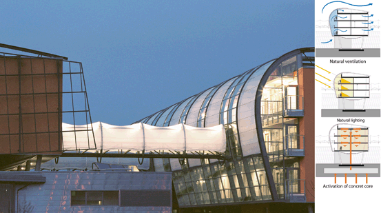
Facade view, technology center in Erfurt
Fig. 6.143 
Scheme of chimney effect (above right, from above to below). Air circulation, solar production, and thermal system


6.38 Complex Climate System 2: Building Reuse

Prairie dog
Potential Ideas from Nature
For the search of possibilities of the influence and thermal capitalization of present materials for a building, organisms in nature that connect passive currents with an activation of a “building part.”
The hills of the mole Talpa europaea are variously designed and/or laid on a slight slope so that they lie at different heights. The moles ventilate their connecting passageways as such using the Bernoulli principle. Naturally ventilated tunnel structures are built by sea inhabiting lugworms of the family Arenicola with particularly designed openings that funnel air in. Around one opening of their tunnel they form a hill; on the other opening an indentation. With this configuration, they fulfill the conditions for a pressure differential, a small “tidal power plant.”
Ideal and natural functionalities are
-
Passive ventilation with a “tidal power plant” (vacuum and funnel effect),
-
Passive ventilation with a chimney effect (induction),
-
Activation of thermal storage masses of present material environment, and
-
Active closing of openings
The functional principles and the adaptations to specific given environments based on these precedents were adapted by Pohl Architects to a preexisting building at the Bauhaus University Weimar. For a former brewery building with thick walls in the basement level a complex thermoregulating system (Figs. 6.145, 6.146, 6.147) was developed that is functionally comparable to the natural precedents, in consideration of

Bauhaus University Weimar: a former brewery building and b with thermoregulating facade

Building section with illustration of the air and temperature flows

Detail of elevation with facade flaps
-
The integration of cross ventilation sluices for passive air circulation;
-
The use of the vertical draft effect with a specifically constructed updraft facade: it forms a vacuum, providing for ventilation as well as serving as a warm buffer when air sluices and facade flaps are closed;
-
The use of the natural topography and temperature differential of a cool (north-facing) street side to a warm (south-facing) back side to achieve cross flow for cooling (summer);
-
The use of preexisting storage masses in the basement and ground levels: over 1 m thick stone walls store and buffer heat; and
-
The detection of warmth and air quality, activation of thermoregulating elements.
6.39 Spatial Panels

a Sea urchin shell “sand dollar.” b REM Image of the interlocking teeth of individual plates of the sea urchin shell

Computer simulation and structural calculation
The plate members of the sea urchin shell are generally joined together by bracing elements in each cell. This idea was applied to the structure of a pavilion at the University of Stuttgart. Computer-based, robotic fabrication enabled the precise production of the individual members. Plywood panels 6.5-mm-thin were joined into spatial shell elements. The research group of the ICD and ITKE institutes at the University of Stuttgart, under the leadership of A. Menges and J. Knippers respectively, managed to use only 1.6 m³ of wood for 200 m³ of total interior space. (Figs. 6.149, 6.150, 6.151, 6.152, 6.153, 6.154, 6.155)

Robot fabrication

“Finger joint” connections

Bird’s eye perspective

Night view

Interior view

First structure element
6.40 Spines

Spine in comparison to a ship’s mast, which is stabilized with riggers (crossbeams) and shrouds (cables)

Individual vertebrae of the structure for a 260-m-free-spanning roof
“Extensive studies on the architecture of the vertebrae of humans and various animals have led the author (1874) to the conclusion, that human as well as animal spines represent a framework construction. The framework was and is the only mechanically possible construction for an entity such as the spine, not only of man but also of animals, for the most varying roles: connecting a pair of extremities to the other, providing the main framework for the entire body of a vertebrate, carrying the bowels, the head, and the extremities, and can support itself on both pairs of extremities or only one pair… . The main difference between the human and animal spine resides in the fact that, with the former, the corresponding, supporting, perpendicular cross-beams come to the fore due to the predominantly upright position. The spine of the quadruped is a truss system, as it is with our modern, iron railroad bridges….” (from Real-Enzyclopädie der gesammten Heilkunde, Medicinisch-chirurgisches Handwoerterbuch für praktische Aerzte, 1893–1901)
Frei Otto has already concerned himself with the structural system of the spine and exhibited a series of comparison studies, that relate the spine with frame structures and tensioned, freestanding masts. In his early work, on the basis of the foundational studies of Frei Otto’s galloping crocodiles, Göran Pohl developed a structure of poured and cast elements that are strung together and articulated like the vertebrae (Figs. 6.157, 6.158, 6.159). Instead of the muscles, tendons, and ligaments used in anatomy, he used steel cables, which are integrated in pre-tensioning and retained in their pre-tensioned condition by an electrohydraulic tension system. The spine system, as interpreted in architecture, is tensioned in the longitudinal as well as in the radial and counter-radial directions of the arched support beams. The construction consists of altogether ten beams arranged in a fan with each beam consisting of up to 26 individually strung vertebrae. With the tensile structure strung between, it spans 260 m unsupported. Pohl further developed this structure and later implemented it in a competition entry for a new design of the natatorium and velodrome in Berlin during Berlin’s application for the 2000 Olympic Games (Fig. 6.158, 6.159).

Section from a model of the spine-supported structure

The model shows the dominant spine supports and the delicate net structure of the roof
6.41 Spatial Structures of Curved Modules 1

Sclerenchyma skeleton of an Opuntia
Curved, free-form surfaces for architectural application: roofs, envelopes, and facades can be developed from the abstraction of the Opuntia structure (Figs. 6.161, 6.162, 6.163, 6.164, 6.165).

Geometric abstraction of the sclerenchyma structure of an Opuntie

Free-form shell model with spatially curved modules

Envelope form in a 3D model

Model attempt of a free-form shell following the precedent of the sclerenchyma of Opuntia

Model
Planar elements of relatively long length and thin section assume the function of the major and minor supports. During assembly the minor supports and in turn the major supports are elastically deformed; they adjust themselves to an equal distribution of weight and stress, an effect that leads to a stable structural form of a shell. With observation of the system of forces in section, lateral forces due to the horizontal portions of stress are found to emerge at the bottom of the structure.
Malleable building materials can be joined together into spatially complex entities. At the SAS, School for Architecture of Saarland, Göran Pohl with his B2E3 Institute for Efficient Buildings developed concepts using curved wood strips that yield a free-form envelope structure with higher stability.
6.42 Spatial Structures from Curved Modules 2

Curved elements yield stable structures for nest constructions of weaver birds
An analogous, architectural development uses the braiding method in a similar manner to the precedent in nature: The ICD, A. Menges and the Institute for Building Structures and Structural Design (ITKE), and J. Knippers of the University of Stuttgart realized the idea of curved building modules in a temporary research pavilion using wood . Computer-based design, simulation, and production processes enabled this structure. The experimental construction consists of elastically curved plywood strips that were joined together into a complex support structure. With the curving of 10-m long, 6.5-mm-thin birch plywood strips the self-stabilizing structure is set under its own tension. The soft plywood strips then join themselves into a rigid structure (Figs. 6.167, 6.168, 6.169, 6.170, 6.171).

Construction of a support of thin, curved elements

Computer-based design and simulation results from above to below: data model for fabrication (a and b) and curved model (c and d)

Top view

Interior

Computer-driven robotic fabrication of the individual plywood strips
6.43 Layered Tissues

Layered tissue of the sclerenchyma skeleton of an Opuntia leaf
The structural tissues can become pressure-resistant and rigid in their cell walls through the process of lignification (i.e., trees). Collenchyma is the name of the structural tissue of growing and herbaceous plant parts. These cells are capable of dividing and growing, therefore not lignified. In contrast, the lignified sclerenchyma consists of dead tissue, which is formed out of thick-walled, narrow cells. Sclerenchyma does not however appear in young plants, only in matured ones; sclerenchyma fibers are one example.
In a similar manner to the layered tissues of sclerenchyma, as they have been demonstrated in the natural precedents, the product designer Jens Otten developed a chair as his diploma thesis at the Kunsthochschule Kassel that focuses on lightness instead of material mass. The surfaces are extremely porous and form only an “interface” between the sitter and the chair legs (Figs. 6.173, 6.174, 6.175). The shell of the seat is constructed from three layers of airplane plywood each with 1.5 mm thickness, glued together at connection points. The construction method entails a spatialized framework in its essence, a highly resolved plywood shell, in which succeeding veneer layers change their direction per layer. The main direction of wood grain is in each case arranged in the lengthwise direction of the individual strips. The shell consists of 60 individual strips and weighs 1013 g. Jens Otten refined this build typology in the frame of his activity at the School for Architecture, Saar within the research project BOWOOSS under Göran Pohl , and translated it to free formable building facade parts (Fig. 6.176).

Generation of a shell from thin, curved individual elements

(above) Detail of the seat shell

(below) Chair model

Further development for free formed building facade parts (model)
6.44 Pneu

Unfurling of the poppy flower due to the increase of turgor pressure in the flower petals. The flower unfurls as a pneu
The pneu is an air- or liquid-filled system that is subject to a pressure difference (Figs. 6.178 and 6.179). It consists of a flexible and tensile membrane that contorts in the direction of a less dense medium in a pressure differential and therefore stabilizing its surface. The built-up internal pressure of air or liquid affects the outer membrane, which in turn builds up a resistance force to this pressure because of its material rigidity. Additionally, a resistance pressure is produced from the medium (air or water) surrounding the pneu. In a pneu there always exists a relationship between internal pressure, the geometric constraints, the stability of the membrane, external pressure, and the resulting form of the pneu. For the nonmoving parts of the pneumatic structure, the air or liquid medium becomes a support medium and support element with the absorption of the outer loads in a closed system. A consistent pressure differential is required for the stabilization of the membrane, which must be sustained by a control system that adapts to changing conditions of the environment: If one of the conditions changes, then the geometric form also changes. This necessary regulation, used as an actuator, enables wanted movements in a structure and relates to the pneumatic and hydraulic actuators of nature.

Air structure in soap bubbles

Pneumatic system, prototype from student work developed under the direction of Göran Pohl for a media skin at the School for Architecture Saarland

Pneumatic lifting device
Pneus are not only used as structural elements in nature, but also as initiators of movement. For this purpose there exist the most diverse applications (Fig. 6.180); the basic principle for movement always rests on form change because of the uptake or removal of air or fluid (fly wings, spider legs, earthworm, flower petals, Mimosa, …)
Pneumatically supported structures are predestined for movable and thus transformable structures because of their lightness (Fig. 6.181). These kinds of structures, which admit changes to their shapes and carry out movement from inside out and not rigidly moved as solid entities, are the goal of the research at the TU Berlin under the leadership of Mike Schlaich and Annette Bögle (HCU Hamburg) .

a and b Utilization of a pneu for moving roof systems at the TU Berlin, Mike Schlaich
6.45 Solid, Efficient Load-Bearing and Heat-Insulated Lightweight Structures

Supporting skeleton of the sea sponge as precedent for gradient optimized building materials
The biological principle of optimized, stress-bearing, solid lightweight structures and optimal heat insulation stand at the focus of the research activities of the universities in Stuttgart and Berlin. The research teams have produced concrete of a particular mixture and set with expanded clay aggregate and can be poured into light wall and roof building members (Fig. 6.183).

Support structure, detail of a test body for gradient concrete, produced at ILEK, University of Stuttgart
The principle of such lightweight building methods can be explained in nature with the construction of bone. In a bone, the areas with higher stress receive more strength and exhibit increased production of spongy bone (Spongiosa), whereas areas with less stress exhibit in relation many pores and cavities. With the increase of rigidity in bones, the organic mass also increases. Similarly the other way around, with decreasing structural bone material the rigidity decreases.
In concrete it was attempted to induce focused strength by varying the amount of porosity throughout a form. The reduced weight of more porous concrete also reduces the load-bearing capacity of the material and vice versa. Using this characteristic, monolithic building parts were successfully produced according to the direction of loads with improved heat-insulating properties. To achieve the improved insulation, highly porous aggregates are added, resulting in so-called infra-lightweight concrete .

Gradient concrete floor with differently treatable fields, developed by Pohl Architects and Lightweight Construction Institute (Leichtbauinstitut) Jena
A research team of Mike Schlaich at the University Berlin and specialists of the ILEK, Institute for Lightweight Structures and Conceptual Design at the University of Stuttgart under Werner Sobek, developed the infra-lightweight concrete further under the label “Gradient Concrete” and were able to vary the solidity and heat-insulating ability over a section of concrete (Fig. 6.183). High-stressed zones of structures can be located with computer-supported calculations and, with precision, structurally strengthened. Therefore, less structurally important regions can be completed with infra-lightweight concrete , leading to other positive effects (Fig. 6.184 and 6.185): with gradient concrete, well-insulated exterior walls can be finished without additional insulating layers, resulting in building parts that are reduced in overall weight, easier to transport, and more efficient in their raw material consumption (Figs. 6.185 and 6.186). The decreased raw material usage correlates to a reduced carbon footprint of the building material.

Stress distribution of FE model of a floor deck under its own weight

Gradient concrete, implemented in a floor deck with varying distribution of the infra-lightweight concrete
6.46 Sonar

Bats recognize their environment using sonic waves
The echolocation of bats provided inspiration for the design of the pavilion for the National Garden Show (BUGA 2011) in Koblenz. The structure originated under the leadership of Mandfred Feyerabend and Markus Holzbach of the Fachhochschule Koblenz and codeveloped by students .
The echolocational call of the noctule bat, a species of bat indigenous to the area, can be made audible for humans with the aid of sound technology. Using a music editing program the sound waves of the calls were visually represented as an oscillogram (Fig. 6.188a). The resulting graphic illustration of the sound pressure level of the bats’ echolocation with relation to time was translated to the layout of the future pavilion (Fig. 6.188b). For its basic form the structure is designed according to naturally occurring catenary curves, for example in spiderwebs, interpreted as supporting arches. In order to finish the structure using small wood members, the surfaces had to be divided into parallel sections of three planes. These three planes stand each at 60° to one another, so that a spatially stable triangle and hexagonal grid is produced, as it occurs with beehive honeycombs in nature. The spatial network of small wooden rods, which consists of an overtruss, undertruss, and diagonal connecting members, was implemented following a continuous digital work process. The 3D basis data of the complete frame for the pavilion described ca. 6000 members and all their connections. The oscillogram of the noctule bat’s echolocation was then projected on the floor of the pavilion structure with the use of LED light strips; the human-audible echolocation calls were emitted over loudspeakers (Figs. 6.189, 6.190).

a and b Echo calls of bats are translated into a structure layout

Sonar pavilion at the National Garden Show in Koblenz 2011

Detailed images
6.47 Fiber Composite Sensors

Fiber bundle and composite of a bamboo root
In relation to the seeing, hearing, and tasting capabilities of natural organisms, engineers are trying to produce “perceptions” in our technology that could be achieved using new techniques, such as building sensors into lightweight-fiber composite constructions. At the Technical University (TU) Chemnitz new methods are being pursued for the steering of complex systems that are comparable to natural systems both in their generation and in their function .
Composite structures, which exhibit an optimum of efficiency, functionality, precision, adaptivity, capability for self-repair, and lifespan, stand at the focus of this development. Fiber and textile strengthened plastics offer particular advantages because of the high variability in the adjustments of a desired characteristic profile and their high potential for lightweight structures. An interdisciplinary cooperation of scientists, of the Competence Center of Lightweight Structures (Kompetenzzentrum Strukturleichtbau, SLB) e.V. at the TU Chemnitz with the professorship of lightweight construction and plastic manipulation under the leadership of Lothar Kroll and the professorship of circuitry and system design, successfully developed so-called direct material control (DMC) system regulation (Figs. 6.192, 6.193, 6.194, 6.195, 6.196). Active structure concepts have the ability to adapt their behavior and characteristics to a multitude of outside influences. The high flexibility in the structural design and technological execution of fiber–plastic composites primarily allows active structures to be outfitted with integrated sensors and actuators and to connect to intelligent and complex systems with an appropriate control strategy in combination with a capable signal manipulation .

Schematic construction for the integration of sensors

Wire sensor stitched into a textile

Sensor embedded in cement mortar

Integrated measurement and data acquisition

Results of the integration of sensors in fiber-strengthened concrete: Both the strengthening fibers and the concrete expand and contract with rising and falling temperatures
The first stitch sensors developed at the SLB e.V. were given their first application in the innovative DMC system. The textile-like fabricated sensor is an element of a variably constructed lightweight composite structure and serves to generate the controlling signal, that is, for a robot. The system commands self-adapting and evaluating electronics, which on the one hand allows adaptation to outside requirements and on the other realizes a standardized output of data. The further development of intelligent fiber composite materials leads, based on the integration of information, sensory, and actuator technology, to complex function-oriented systems. Up to now the most diverse materials have been available, that is, piezoelectric, fiber-optic fibers (so-called fiber Bragg grating) , also shape memory alloys and prefabricated information elements, that is, strain gauge strips. From these components active composite materials or “smart composites” can be produced with targeted characteristics that are particularly suited for application in stressed building parts consisting of fiber composites. An example of an application in architecture is the ability to determine the amount of moisture in cement-bound systems with means of stitch sensors. Further applications occur for the measurement of strain in fiber–plastic composites or in fiber-based probes .
6.48 Reactive Envelope Structures

Spruce cones, right opened (dry conditions) and left closed (wet conditions)
Technical Application
Reactive envelopes following the precedent of conifer cones have incited researchers of the ICD under the leadership of Achim Menges at the University of Stuttgart to develop systems that can react to weather conditions without motors. A. Menges and Steffen Reichert executed studies for this purpose: “This anisotropic elongation was used to develop an air humidity-driven veneer composite. A thin cut of maple wood veneer was utilized, as it exhibits a relatively high tangential elongation with comparably low modulus of elasticity. A change in the relative humidity from i.e. 40–70 % leads to a quick change in size of the veneer, which is translated to a notable change in shape: from an originally flat form to a highly warped one. The veneer composite element uses the reactive material characteristics in surprisingly simple building part that is at once an integrated sensor, energy-less actuator, and modulating flap. An integrated functionality of this type on the material level allows complex, decentralized behavior patterns without any control units. Each veneer composite element reacts to its specific location, functions completely independent from the others and forms in combination a highly robust, decentrally driven, adaptive system” (Figs. 6.198, 6.199, and 6.200)

Reaction of the veneer elements to humidity

Opening mechanism of a roof structure: left closed (wet conditions) and right opened (dry conditions)

Computer-based generation for the translation to CNC cut patterns of the roof surfaces
6.49 Ventilation Systems for Breathing Envelopes

Lung—bronchial anatomy
Technical Interpretation
The technology of breathing components developed by Lidia Badarnah at the TU Delft (Badarnah and Knaak 2007) translates the active principles and methods of natural respiratory and circulation systems to elements for building envelopes (Figs. 6.202 and 6.203). The biomimetic-inspired breathing envelope for buildings functions on the following principles:

a–d Construction of the basic components of a breathing envelope

a Arrangement in an envelope system. b Elevations and section
-
1.
Generation of pressure gradients with the movement of building parts
-
2.
Extension and contraction of volumes for the generation of “suction” and “exhaust”
-
3.
The system is hierarchically membered
-
4.
The air exchange is controlled by the shape of the surface form.
The respiratory organ, and the ventilating system as a whole, is an active system and forms the protective envelope for the building. The envelope consists of singular active components that are arranged similar to cell walls. The macro-arrangement of the cells as well as the microsystem within the cells react dynamically .
The cells are constructed of membranes of different porosity and result in gas exchange. They are partially gas permeable, half-permeable to impermeable. The inner membrane elements form, using a double membrane system, lung-like chambers as central respiratory organs and are similar to air supported expanding structures. These chambers are coupled to sensors and can elongate themselves with piezoelectric signals and change in volume. They are outfitted with openings and simple flap mechanisms that intake air with expansion and remove air with contraction. The complex system can simultaneously “inhale” and “exhale”: While certain chambers allow for the intake of air, others provide for the outflow. Air then cannot flow in the opposite direction. With development of new materials, a self-adaptive facade technology is proposed that can adjust itself intelligently to changes .
6.50 Thermoregulating Envelope Structures

Birds and mammals have developed physiological traits that enable necessary heat insulation and body temperature regulation for thermoregulative function
Technical Interpretation
Living nature contains an uncountably large number of organisms that could act as the model for the technological development of thermoregulatory processes. The unique strategies of natural thermoregulation enable an adaptation behavior of the “envelope” as the answer to variable temperatures in the environment and inside the organisms. The various species are individually adapted to different climate regions with certain temperature ranges within which the organism can survive. The examples in nature selected here for observation were chosen due to their having developed strategies and mechanisms for a constant body temperature that it can adhere to despite variable climates (Figs. 6.205 and 6.206).

a and b Cooling facade: integrated irrigation system for water evaporation in the building envelope

Functioning principles that were used for the development of the cooling facade
Thermoregulating systems of living nature were more closely investigated at the TU Delft by Badarnah et al. They focused themselves particularly on the following systems and functions:
-
Termite hills—passive ventilation
-
Tuna fish—heat exchange
-
Human skin—transpiration
-
Birds—Cooling by means of larynx vibration
The group at the TU Delft (Badarnah et al. 2010) compiled a classification (Fig. 6.206) of possible applications for building envelopes and discussed primary interpretations of these systems. These interpretations included an evaporation-cooled wall for application in arid regions (Fig. 6.205). Figure 6.207 illustrates a system for warm, arid, or humid regions using an envelope with an enclosure system that, when moist, allows air to flow inward and during dry and hot weather conditions allows air to flow outward. The system consists of four integrated modules (Fig. 6.206, courtesy of Lidia Badarnah). (1). “Stoma Brick”: the functional part of the thermoregulation system consists of an outer filter with filter hairs (filter for debris) and a “venous” enclosing flap that enables opening and closing in relation to air moisture. A large part of the inner layer is spongelike to absorb moisture for evaporation. (2). “Mono-brick”: contains the irrigation mechanism. (3). Steel frame. (4). Inner layer: HEPA filter for air purification or acrylic glass panels for window openings .

View of a cooling facade for an arid region
6.51 Modifiable Surface Elements 1

Strelitzia
The movement of the Strelitzia flower does not occur autonomously but dependent on an outside influence. The reversible elastic deformations require no additional “mechanics” and can function with a nearly endless number of uses. The Plant Biomechanics Group at the University Freiburg (Prof. T. Speck) investigated the function morphology of the Strelitzia and confirmed that the flap mechanism retains its reversible functionality even after over 3000 uses (Fig. 6.209).

a and b Flap mechanism of the flower and c measured displacement

Reduction of the stress at the fold through biomimetic optimization of contour lines
At the University of Stuttgart through the Institute for Building Structures (ITKE; J. Knippers) and the Institute for Textile Technology (ITV) Denkendorf, this function was then translated to a shading lamella that reacts to an external force with a lateral bend due to lateral torsional buckling. The research results concluded in a patented technology for a shading facade, Flectofin© (Figs. 6.210, 6.211, 6.212, 6.213, 6.214)

a and b Finite element analysis of facade shading

Abstraction of a section: the laterally displaced spine leads to lateral torsional buckling of the entire shell element

a and b Model illustration of the functioning concept

Flectofin© in the first mock-up
6.52 Modifiable Surface Elements 2

Venus flytrap Dionaea muscipula; the lamina move following the principle of thigmonasty
Natural apparatuses that open and close themselves without mechanical elements possess a high potential as a precedent for application in the building industry. Light reflecting and shading systems for buildings that essentially draw on material–property changes for their mobility and thus simplify the mechanical building parts could be drawn from these natural precedents. (Figs. 6.216, 6.217, 6.218, 6.219).

a Movement principle

b and c Calculation study of elastically deformed strips

a and b “One Ocean” EXPO Pavilion, Korea, SOMA architects

a and b Facade segment of “One Ocean” EXPO Pavilion, Korea
The opening elements in the facade of the Theme Pavilion of EXPO 2012 in Yeosou, Korea by SOMA architects achieve movements with elastic deformation. Inspired by the research on Flectofin©, Knippers Helbig Advanced Engineering developed the technical concept of the moving elements.
The up to 15 m-tall-lamellae with strengthening ribs on both sides consist of only 8-mm-thick glass fiber-reinforced plastic. They are elastically deformed by an extrinsic force initiated from above and below.
6.53 Multiaxially Modifiable Surface Elements

The Mimosa plant in opened condition
Mimosa conveys a touch stimulation inside of the plant so that neighboring fronds react. This reaction is not autonomous but is caused by change in turgor pressure, triggered by a chemical messenger substance or electric impulses. Movement studies on plants have inspired the research teams of Pohl Architects and Knippers Helbig Advanced Engineering to the most diverse technical interpretations independently from one another (Figs. 6.221 and 6.222). For a covering of a courtyard in a former monastery, the teams cooperatively developed a multiaxial moving envelope (Figs. 6.223 and 6.224). For the protection of spectators of the local festivals in Feuchtwangen, a new type of roof envelope is being planned that can react to rain, sun, and heat and, like the Mimosa frond, consists of individually linked, adjustable panels. This adjustable roof developed analogous to the nastic movements (not autonomous) of plants consists of a leaf plumage with seven individual “pinnae” that span the entire breadth of the courtyard. In the opened position the panels are driven to the back. With the onset of rain detected by sensors the roof closes itself within 2 min. For the air circulation in the audience space the panels of the roof can smoothly position themselves into a slanted position. The vaulted shape of the panels and their shading structures provide for thermal wind ventilation and cooling. In the closed position the rain on the roof is directed into an integrated gutter system. The panels consist of specially finished ultra-lightweight parts entirely of glass fiber-composite construction.

Movement simulation with structural analysis

Movement in different weather conditions: above the amplitude of movement, middle in sunny conditions, below in rainy conditions

The roof over the monastery courtyard in closed position with light staging

Various open roof positions. The complete retracted position of panels is not represented
6.54 Reactive Contraction Systems

Muscle biology

FESTO pneumatic muscle
Lightweight structures, like the stressed ribbon bridge, vibrate heavily under the weight of pedestrian traffic. At the TU Berlin under Mike Schlaich and Achim Bleicher , an active vibration control system was developed and tested using artificial muscles to reduce the exceptionally high susceptibility to vibrations in stressed ribbon bridges using carbon fiber-reinforced plastic bands (Figs. 6.227, 6.228, 6.229, 6.230). The concept of reactively contracting systems is based on the controlled input of induced forces in the handrail structure. For the generation of these forces industrially manufactured pneumatic muscles of the firm FESTO (Fig. 6.226) were used. These artificial muscles expand themselves radially with an increase of internal pressure causing them to contract in length. With especially developed algorithms, the contractions and the induced forces are regulated in relationship to the occurrence of bridge vibrations, thereby stabilizing the bridge with “muscle strength.”

Actively regulated stressed ribbon bridge with sensors, actuators, and controllers

Pedestrian induced accelerations in the natural vibration frequency with and without active vibration controls

Load-bearing/vibration damping simulation, “walking” on the prototype, TU Berlin

Pneumatic muscle with related equipment
6.55 Self-responsive Movements, Fin Ray Effect®

Tail fins of two supporting fin rays
The Fin Ray Effect® discovered with the movement patterns of fish fins depicts a function principle that is interesting for various technical applications. The “Fin Ray Effect®” is the protected brand of the firm EvoLogics and was developed for diverse applications, such as form-adapting gripping elements for gripping devices or demonstrations at exhibitions. With this naturally occurring effect the elastically coupled element “fish fin” reacts to pressure with a movement in the direction of the pressure (Figs. 6.232 and 6.233). The same happens when bands running in the direction of the fin rays are energized. With a deformable tail fin of this type the fish can propel themselves from the alternating eddies of the vortex streets they produce. Researchers at the TU Berlin with Mike Schlaich and Annette Bögle of the HCU Hamburg are developing applications for construction that can use the Fin Ray Effect® (Fig. 6.234). An openable joint solution for textile canopies and membrane roofs according to the fin ray principle does not behave like traditional joints to the principle of squishing the material, but instead uses the geometric deformability and the system-given nestling of the structure.

A subtle shift of the fingers moves the fish fin

(above) Fin Ray Effect® on a plaice

Fin Ray Effect®: Different movement patterns illustrated in model. The number of cross braces is not important for the bending behavior of the entire system
6.56 Flexible Shells

Pill bug Armadillidium vulgare
Technical Application
Interesting possibilities of design development are offered by these relocating shells, present for example in pill bugs. Similar principles have been known for quite some time: In the Middle Ages knights’ armor was designed to offer a certain freedom of movement despite the rigidness of the material. Joint pieces at the knee and elbow were especially outfitted with elements that overlap each other in the manner of the pill bug.
At the School for Architecture Saar of the HTW Saar, studies for a segmented bridge following the precedent of pill bugs have occurred under the leadership of Göran Pohl (Figs. 6.236, 6.237). The roll bridge is composed of individual elements that can be rolled together like the shells of the pill bug. The elements are connected to one another with a hinge joint that hinders lateral torsion and enables it to be rolled up. The bridge unrolls all of the segments to a slightly overextended, curved position yielding a structurally sound arch-shape form. The bridge is then operational in the completely unrolled position. Connecting the individual segments with the means of cables enables the bridge to be rolled up to a compact bundle like the pill bug. A further connection is considered for the underside of the roll bridge between each neighboring element, which would distribute the loads occurring in the unrolled position to the rigid frame pieces of the bridge. With this construction method a small roll bridge for pedestrians for short spans is imaginable; one that is flexibly opened and closed.


Roll bridge in the process of movement (a and b). The bridge rolling together (c and d)

Model of a roll bridge
6.57 Self-healing

Tree wound with clearly visible enclosure as a result of the self-healing process
The vine Aristolochia macrophylla was investigated in the botanical garden at the University Freiburg as study object for the effects of self-healing. The process is carried out by the closure of a wound in several phases. In the first phase parenchyma cells swell in the wound and seal it (Figs. 6.239, 6.240, 6.241).

a–c Self-healing in Aristolochia macrophylla. Parenchyma cells close the wound

Self-healing after an outer wound on the bean plant Phaseolus vulgaris (a) early phase of self-repair: parenchyma cells fill the wound, (b) later phase with swelling and wound closure

Section of the vine Aristolochia macrophylla (a) 1-year-old trunk with closed ring of sclerenchyma fibers. (b) As a consequence of the yearly growth, a 2-year-old-trunk displays a growth of the xylem and a segmenting of the sclerenchyma ring
The sealing presumably occurs by a viscoelastic–plastic expansion of cells, driven by cell-turgor pressure. Subsequently, parenchyma repair cells form that grow into the wound and thicken their cell walls (Fig. 6.242b, c). The cell shape and the cell wall thickness of normal parenchyma cells and repair cells are quite different.

a Layer construction from above to below: Air with high pressure. Green = Active repair layer. Membrane. b–d A hole in the air chamber is subsequently sealed with the foam until the hole is completely filled and the air loss stopped

(above right) Tensairity® system

(middle) Components of the Tensairity® system are a long pressure bar, an inflatable membrane for the pneumatic base element, cables for radial and counter-radial tensioning, anchoring parts
In cooperation with the Swiss firm Prospective Concepts AG and the EMPA Dübendorf, the biological self-healing process was translated to a fabricated membrane using the Tensairity® concept. The technology consists of an air-filled membrane, pre-stressed with a slight internal pressure of 50–500 mbar, that is stabilized by cable elements and pressure bars. In the instance of damage to the membrane air begins to flow out of the Tensairity® element. As the air is introduced into the system with little pressure, it escapes slower than usual. In the studies the biological principle was translated to a self-healing membrane. The technological development is based on an additional foamy, “cellular” membrane layer, which can reseal the membrane in case of damage. The repairing layer is located on the inside of the membrane. The repair process functions in a similar manner to the natural precedent: the injury is sealed by a closed pored foam layer (Fig. 6.242). The possibility of self-repair depends on the amount of damage. Layers with a polyurethane basis have already yielded promising results. Initial uses for lightweight bridge structures and pneumatic roofs are currently being tested (Figs. 6.243, 6.244).
6.58 Bambootanics

Pine cone seen from below
Technical Application—Bambo(o)tanics
Bambo(o)tanics is a self-growing structural system using bamboo, which was developed by Niko Feth at the School for Architecture with G. Pohl and L. Bergrath, HTW Saarbrücken. Following the insights of phyllotaxis of pine cones, the structure consists of individual, modular canopies formed from bamboo stalks and strung together (Figs. 6.246, 6.247, 6.248, and 6.249). For the construction of the individual canopies, the bamboo stalks are bent into the canopy form while being grown. The curving of the stalks according to Fibonacci spiral yields canopy surfaces with minimal shading on the plants themselves and a regular structural system in which the plants mutually support each other. With parametric, digital generation according to the rules of phyllotaxis, the membrane elements are configured to serve as rain and sun protection for the users and solar energy collectors. They are hung between the structural bamboo members. Rainwater is captured on the membrane skin and funneled to the roots of the plants. The photovoltaic film-coated, semi-permeable membranes are aligned following the principles of phyllotaxis arrangement, so that the growth of the bamboo branches and twigs is not hindered in their natural tendency to fill light gaps. This manner of construction is particularly suitable for the creation of weather protected shelters and offers a system that integrates technology and nature for a canopy in tropical regions .

Bambo(o)tanic during its growth process

Fully developed bamboo canopy for an outdoor market in a tropical region. The solar membranes serve as Sun and rain protection, lead water to the plant roots, and integrate photovoltaic (PV) modules for solar energy production

Plan view of the system: Hexagonal arrangement of the supports, arrangement of the bamboo stalks, and arrangement of the solar membranes

Elevation
6.59 Floating Volumes

a Portuguese man o’ war Physalia physalis b Japanese chestnut
Floating Habitats
The system inspired by the Portuguese man o’ war Physalia physalis is a concept for an urban habitat structure for inland bodies of water, which was developed by Claudia Pommer in the frame of her university thesis at the Institute for Industrial Design in the subject area of engineering and industrial design of the Hochschule Magdeburg-Stendal under Ulrich Wohlgemuth (Figs. 6.251, 6.252, and 6.253). Inspired by the polyp colony organism Physalia physalis, the idea emerged for a “camping site philosophie” on water. A complex, urban habitat structure yielded itself as a combination of differently sized public spaces, housing units, and connecting footbridges following the precedent of the Japanese water chestnut. Every platform offers five docking positions for the ca. 32 m2 large, modularly constructed living units. Each unit is movable with the use of an electric engine so that the arrangement on the water can always be differently reconstructed. Therefore the units are able to attach and detach at different docking positions as they wish. A pontoon forms the core of living unit. For protection while docking, a surface of flexible material that can adjust to the movement of water surrounds the core and offers a place for relaxation. A pneumatic structure with a place for sleeping is attached to the top of the pontoon. The “cocoon” dwelling is protected by an adjustable covering with integrated solar panels that provide energy for the cocoon. To lend the individual units a certain level of individuality and recognizability, different colors, patterns, and lighting can be used (Fig. 6.254).

Construction of the envelope

Visualization of habitat structure

The Physalia floating volumes are drivable with an electric motor

Habitat structure with centrally located, rigid platforms and relocatable Physalia dwelling units
6.60 Sources, Figure Index, Authors and Project Contributors in Chap. 6
Further information and advice for the subchapters in Chap. 6. If not written separately, the institutions are based in Germany.
6.60.1 Biomimetics on the Basis of Algae, a Biological Example
Hamm, C. 2005, Kieselalgen als Muster für technische Konstruktionen, BIOSpektrum 1/05, 41–43
Figure 6.1 Hustedt Collection, Alfred Wegener Institute Bremerhaven, Photo: Hinz/Crawford
Figure 6.2 L Friedrichs, Alfred Wegener Insitute, Helmholtz Centre for Polar and Marine Research
Figure 6.3 after IL38 Diatomeen,2, S. 45
6.60.2 Pool Research as Biomimetic Method in Application
Figure 6.4 Construction scheme of a diatom shell. Image: Pohl, G., Otten, J., Research group BOWOOSS, B2E3 Institute for Efficient Buildings of the HTW Saar
6.60.3 Pool Research: Abstraction through the Classification of Biological Precedents
Figure 6.5 Excerpt from the classification of diatoms, Pohl, G.
Figure 6.6 Basic forms of diatoms, Pohl, G.
6.60.4 Pool Research: Analysis and Evaluation
Figure 6.7 C. Hamm, Alfred Wegener Insitute, Helmholtz Centre for Polar and Marine Research
Figure 6.8 Alfred Wegener Insitute, Helmholtz Centre for Polar and Marine Research
Figures 6.9 6.10, and 6.11 L Friedrichs, Alfred Wegener Insitute, Helmholtz Centre for Polar and Marine Research
6.60.5 Pool Research: Abstraction of Geometric Principles
Figure 6.12 Classification Pohl, G., graphics Pohl, G., images from Alfred Wegener Insitute, Helmholtz Centre for Polar and Marine Research
6.60.6 Pool Research: Translation into CAD Models
Figures 6.13, 6.14, 6.15, 6.16, and 6.17 Pohl, G., B2E3 Institute for Efficient Buildings of the HTW Saar
6.60.7 From Pool Research to Applied Research
Figure 6.18 Pohl, G., B2E3 Institute for Efficient Buildings of the HTW Saar
6.60.8 Generative Design
Figure 6.19 Pohl G.
Figure 6.20 Bartenbach Light Laboratory; Project team Behnisch Achitects, Pohl Architects
Figure 6.21 Project team Behnisch Achitects, Pohl Architects
Figures 6.122, 6.123, 6.124, and 6.125 Pohl Architects
6.60.9 Physical Models
Figure 6.26 Pohl, G., B2E3 Institute for Efficient Buildings of the HTW Saar
Figure 6.27a, b Pohl, G., B2E3 Institute for Efficient Buildings of the HTW Saar
Figures 6.28 and 6.29 Pohl, G., B2E3 Institute for Efficient Buildings of the HTW Saar
6.60.10 Biomimetic Potentials: Ribs and Frameworks
Figure 6.30 Feth, N., Pohl, G., Research group BOWOOSS, B2E3 Institute for Efficient Buildings of the HTW Saar
Figure 6.31 L Friedrichs, Alfred Wegener Insitute, Helmholtz Centre for Polar and Marine Research
Figure 6.32 Feth, N., Pohl, G., Research group BOWOOSS, B2E3 Institute for Efficient Buildings of the HTW Saar
6.60.11 Biomimetic Potentials: Rectangular Frames
Figure 6.33 Pohl, G., B2E3 Institute for Efficient Buildings of the HTW Saar
Figure 6.34 Pohl Architects
Figure 6.35 Pohl, G., Otten, J., Research group BOWOOSS, B2E3 Institute for Efficient Buildings of the HTW Saar
Figure 6.36 Pohl, G., B2E3 Institute for Efficient Buildings of the HTW Saar
6.60.12 Biomimetic Potentials: Layered Structure
Figure 6.37 L Friedrichs, Alfred Wegener Insitute, Helmholtz Centre for Polar and Marine Research
Figure 6.38 Pohl, G., Otten, J., Research group BOWOOSS, B2E3 Institute for Efficient Buildings of the HTW Saar
6.60.13 Biomimetic Potential: Offset Beams
Figure 6.39 Image N. Abarca, Botanical Garden and Botanical Museum Berlin-Dahlem, Free University Berlin
Figure 6.40 Pohl, G., Stolz, F., Research group BOWOOSS, B2E3 Institute for Efficient Buildings of the HTW Saar
6.60.14 Biomimetic Potentials: Incisions and Curvature
Figure 6.41 Image P. Höbel, M. Eng.
Figures 6.42, 6.43, and 6.44 Pohl, G., Stolz, F., Research group BOWOOSS, B2E3 Institute for Efficient Buildings of the HTW Saar
6.60.15 Biomimetic Potentials: Curvature
Figure 6.45 Pohl, G.
Figure 6.46 Pohl, G., Otten, J., Research group BOWOOSS, B2E3 Institute for Efficient Buildings of the HTW Saar
6.60.16 Biomimetic Potentials: Hierarchical Structures
Figure 6.47 L Friedrichs, Alfred Wegener Insitute, Helmholtz Centre for Polar and Marine Research
Figure 6.48a Cuma, Alfred Wegener Insitute, Helmholtz Centre for Polar and Marine Research
Figure 6.48b Pohl Architects
Figure 6.49 Pohl, G.
Figure 6.50 Knippers Helbig Advanced Engineering
6.60.17 Biomimetic Potentials: Fold Systems
Figure 6.51 Pohl, G.
Figure 6.52 Pohl, G., Otten, J., Research group BOWOOSS, B2E3 Institute for Efficient Buildings of the HTW Saar
6.60.18 Translation and Technological Implementation using the example of the BOWOOSS Research Pavilion
Figures 6.53 and6.54 C. Hamm, Alfred Wegener Insitute, Helmholtz Centre for Polar and Marine Research
Figure 6.55 L Friedrichs, Alfred Wegener Insitute, Helmholtz Centre for Polar and Marine Research
Figure 6.56 Pohl Architects, dept. Institute for Lightweight Structures Jena
Figure 6.57, 6.58, and 6.59 Pohl, J., Pohl Architects, dept. Institute for Lightweight Structures (Leichtbauinstitut) Jena
Figures 6.60 and6.61 Pohl, G., Otten, J., Research group BOWOOSS, B2E3 Institute for Efficient Buildings of the HTW Saar
6.60.19 BOWOOSS Research Pavilion: Methods and Results of Building-Biomimetics
Figures 6.62, 6.63, 6.64, and 6.65 G. Pohl, N. Feth, Research group BOWOOSS, B2E3 Institute for Efficient Buildings of the HTW Saar
Figure 6.66 M. Martin, Saarbrücken
Figures 6.69, 6.70, and 6.71 Halbe, R., Roland Halbe Architecture Photography
Figure 6.72 Pohl, G.
6.60.20 Building Biomimetics in Examples: Biomimetics and Analogous Developments
Figure 6.73 Pohl, G.
6.60.21 Structural Optimization
Karlsruhe Institute of Technology, KIT, Mattheck, C.
Sauer A. 2008, Untersuchungen zur Vereinfachung biommetrisch inspirierter Strukturoptimierung,
Diss., FZKA 7406
Hochschule Magdeburg-Stendal, department of Engineering Sciences and Industrial Design, Biller, S., Mühlenbehrend, A. „Die Jahr100 Kurve“
Figure 6.74 Pohl, G.
Figure 6.75 Mattheck C., Sauer A, KIT Karlsruhe
Figure 6.76 Mattheck C., “Stupsi erklärt den Baum,” Publisher KIT Karlsruhe, 4. revised printing 2010, p. 44 and ”Mechanik am Baum“ Publisher Forschungszentrum Karlsruhe, 2002, p. 64
Figure 6.77 Biller, S., Hochschule Magdeburg
Figure 6.78 Biller, S., Hochschule Magdeburg
6.60.22 Self-organization
Dr. Mirtsch GmbH, Mirtsch, F.
Figure 6.79 Pohl, G.
Figures 6.80, 6.81, 6.82, 6.83 Dr. Mirtsch GmbH
6.60.23 Evolutionary Design
University of Stuttgart, Institute for Computer-based Design ICD, Menges, A.
Menges A., 2011, Morphogenetic Design Experiments, Institute for Computer-based Design, University of Stuttgart
Figure 6.84 Pohl, G.
Figures 6.85, 6.86, and 6.87 Menges, A., University of Stuttgart, ICD—Institute for Computer-based Design
6.60.24 Morphogenetic Design
Pohl Architects, dept. Institute for Lightweight Structures (Leichtbauinstitut) Jena
Kooistra W. and Pohl G. (2015), Diatom Frustule Morphology and its Biomimetic Applications in Architecture and Industrial design. In: Hamm, C. Evolution of Lightweight Structures—Biomechanic Adaption and Biodiversity of Plankton Shells: Analyses and Technical Applications, Springer Berlin
Pohl G. (2015), Fibre Reinforced Architecture Inspired by Nature: COCOON_FS. In: Hamm, C. Evolution of Lightweight Structures—Biomechanic Adaption and Biodiversity of Plankton Shells: Analyses and Technical Applications, Springer Berlin
Figure 6.88 Lars Friedrichs, Alfred Wegener Insitute, Helmholtz Centre for Polar and Marine Research
Figure 6.89 Christian Hamm, Alfred Wegener Insitute, Helmholtz Centre for Polar and Marine Research
Figure 6.90 Pohl, J., Pohl, G.
Figures 6.91 and 6.92 Pohl J., Pohl G., Pohl Architects, dept. Institute for Lightweight Structures (Leichtbauinstitut) Jena
6.60.25 Geometric Optimizations: Sectional Optimization
Technical University (TU) Berlin, Institute for Civil Engineering, Chair of Conceptual and Structural Design, Schlaich, M., Gaulke, A.
Figure 6.93 Pohl, G.
Figure 6.94 Schlaich, M.
Figure 6.95 Gaulke, A.
Figure 6.96 Pohl, G.
6.60.26 Hierarchical Structures
Alfred Wegener Institute Bremerhaven (AWI)
Hamm, C. 2005, Kieselalgen als Muster für technische Konstruktionen, BIOSpektrum 1/05, 41–43
Pohl Architects, dept. Institute for Lightweight Structures (Leichtbauinstitut) Jena
Figures 6.97 and 6.98 L Friedrichs, Alfred Wegener Insitute, Helmholtz Centre for Polar and Marine Research
Figure 6.99 Pohl, G., Pohl Architects
Figure 6.100 Pohl Architects
Figure 6.101 Knippers Helbig Advanced Engineering
6.60.27 Evolutionary Urban Planning
Institute for Computer-based Design ICD, University of Stuttgart
Krampe F., Voss C., Ahlquist S., Menges A. 2011, Integrated Urban Morphologies. Entwicklung eines evolutionären, klimaorientierten Entwurfsprozesses auf Maßstabsebene des städtischen Blocks Institute for Computer-based Design ICD, University of Stuttgart
Figures 6.102, 6.103, 6.104 Krampe F., Voss C., Ahlquist S., Menges A. 2011, Integrated Urban Morphologies, ICD Uni Stuttgart
6.60.28 Exterior Surface Effects
http://www.spektrum.de/alias/materialwissenschaft/selbstreinigung-ohne-lotoseffekt/1126247
http://www.bionik.tu-berlin.de/institut/s2skink.html
http://www.bionikvitrine.de/mediapool/99/996537/data/PDFs/Haihaut/Haihauteffekt.pdf
Figure 6.105 Maren Beßler_pixelio.de/ www.pixelio.de
Figure 6.106 Cornerstone/pixelio.de/ www.pixelio.de
Figure 6.107 Bionic StreamForm Frank Wedekind, Saarbrücken
6.60.29 Foundations of Resource-Efficient Facade Technologies
Gosztonyi S., Judex F. , Brychta M., Gruber P. , Richter S., 2012, BioSkin—Bionische Fassaden, Potentialstudie über bionische Konzepte für adaptive energieeffiziente Fassaden, AIT Austrian Institute of Technology, foundation study in frame of the Austrian promotial program “House of the Future Plus,” promoted by the Ministry for Transportation, Innovation, and Technology
Gruber P., Gosztonyi S., 2010, Skin in architecture: towards bioinspired facades. In: Brebbia, C.A. & Carpi, A. (eds.), Design and Nature V, Comparing Design in Nature with Science and Engineering, Volume 138, WIT press, Southampton, ISBN: 978-1-84564-454-3
Figure 6.108 Pohl, G.
Figure 6.109 Gosztonyi S., 2011, BioSkin, AIT Austrian Institute of Technology
Figure 6.110 BioSkin Workshop Team, 2011, BioSkin, AIT Austrian Institute of Technology
6.60.30 Daylight Usage
Gosztonyi S., Judex F., Brychta M., Gruber P., Richter S., 2011, BioSkin—Bionische Fassaden, Potentialstudie über bionische Konzepte für adaptive energieeffiziente Fassaden, AIT Austrian Institute of Technology, foundation study in frame of the Austrian promotial program “House of the Future Plus.” promoted by the Ministry for Transportation, Innovation, and Technology
Figure 6.111 “Licht im Schwamm.” 17.11.2008 Uni Stuttgart
Figure 6.112b, c Richter S., 2011, BioSkin, AIT Austrian Institute of Technology, http://idw-online.de/de/news289131
Figure 6.113 Richter S., 2010, BioSkin, AIT Austrian Institute of Technology
Figure 6.114 Gosztonyi S., 2011, BioSkin, AIT Austrian Institute of Technology
Figure 6.115 Judex F., 2011, BioSkin, AIT Austrian Institute of Technology
6.60.31 Shading
Gosztonyi S., Judex F., Brychta M., Gruber P., Richter S., 2011, BioSkin—Bionische Fassaden, Potentialstudie über bionische Konzepte für adaptive energieeffiziente Fassaden, AIT Austrian Institute of Technology, foundation study in frame of the Austrian promotial program “House of the Future Plus.” promoted by the Ministry for Transportation, Innovation, and Technology .
Figure 6.116 Pohl, G.
Figure 6.117 Siegel G., 2010, BioSkin, AIT Austrian Institute of Technology
Figure 6.118 Siegel G., Gosztonyi S., 2010, BioSkin, AIT Austrian Institute of Technology
6.60.32 Shading and Solar Energy Production
Badarnah, L., Knaack, U., 2008, Shading/energy generating skin inspired from natural systems. Proc. of the 2008 World Sustainable Building Conf. SB08, Eds G. Floiente and P. Paevere, pp 305–312
Figure 6.119 Pohl, G.
Figures 6.120, 6.121, 6.122, 6.123 Badarnah, L., Knaack, U., 2008, Shading/energy generating skin inspired from natural systems
6.60.33 Shading and Directing Light 1
Hertzsch, E., Pohl, G 2011, international Student Workshop on Façade Design & Performance, University of Melbourne, Australien.
Jin, H., 2011, Second Skin Façade inspired from the epidermal stoma of leaves. Design proposals, Bio-Inspired Façade Systems .
http://de.wikipedia.org/wiki/Stoma_%28Botanik%29
Figure 6.124 Pohl
Figures 6.125, 6.126, 6.127, 6.128 Jin, H., 2011, Second Skin Facade inspired from the epidermal stoma of leaves. Design proposals, Bio-Inspired Façade Systems.
6.60.34 Shading and Directing Light 2
Hertzsch, E., Pohl, G 2011, international Student Workshop on Façade Design & Performance, University of Melbourne, Australien.
Pullyblank, D., 2011, Modular Façade inspired by Barnacles. Design proposals.
http://de.wikipedia.org/wiki/Seepocken
Figure 6.129 Sea barnacles, Kiser, K., sxc.hu
Figures 6.130, 6.131, 6.132, 6.133, 6.134 Pullyblank, D. 2011, Modular Façade inspired by Barnacles. Design proposals .
6.60.35 Colors without Pigments 1
Pohl Architects, www.pohlarchitekten.de
Figure 6.135 Pohl G.
Figures 6.136–6.137 Wilhelm J., Pohl Architects
6.60.35 Color without Pigments 2
Gosztonyi S., Judex F. , Brychta M., Gruber P. , Richter S., 2011, BioSkin—Bionische Fassaden, Potentialstudie über bionische Konzepte für adaptive energieeffiziente Fassaden, AIT Austrian Institute of Technology, foundation study in frame of the Austrian promotial program “House of the Future Plus,” promoted by the Ministry for Transportation, Innovation, and Technology .
Figure 6.138 Kirsanov, V., fotolia.de #30191504
Figure 6.139 Gosztonyi S., 2010, based on results from BioSkin Creative Workshop, AIT Austrian Institute of Technology
Figure 6.140 Gosztonyi S., Ledinger S., Abermann S, Haslinger E., 2010, BioSkin Creative Workshop, AIT Austrian Institute of Technology
6.60.36 Complex Climate Systems 1: New Construction
Pohl, G., Technology and Media Centre Erfurt, Tensinet Symposium: Designing Tensile Architecture, September 2003, Brussels, Belgium
Pohl, G., Fabric Architecture march/april 2004,USA
Figures 6.142–6.143 Pohl Architects
6.60.37 Complex Climate Systems 2: Building Reuse
Pohl Architects, Media Center, Bauhaus University Weimar, Erfurt, Germany; info@pohlarchitekten.de
Hochschul- und Forschungsbauten, 2003, Stiftung Baukultur Thüringen
Figure 6.144 Post, K., http://www.klauspost.com
Figures 6.145, 6.146, 6.147 Pohl Architects
6.60.38 Spatial Panels
Institute for Computerbased Design ICD, Menges, A., University of Stuttgart, Institute of Building Structures and Structural Design (ITKE), Knippers J., University of Stuttgart
http://www.itke.uni-stuttgart.de/img/background/95-110829_Above-web.jpg
Figure 6.148aBas van der Steld, F., Hendriklaan 259 A, NL-2582 Gravenhage
Figure 6.148b Seilacher, A. Engelsfriedhalde 25, D-72076 Tübingen
Figure 6.149 Waimer, F., La Mangna, R., Knippers, J., Institute of Building Structures and Structural Design (ITKE), University of Stuttgart
Figures 6.150, 6.151, 6.152, 6.153, 6.154, 6.155 Menges A., ICD University of Stuttgart
6.60.39 Spines
Pohl, G., Pohl Architects: Competition for the Olympic Games 2000 in Berlin
Figure 6.156 André, A. B2E3 Institute for Efficient Buildings at HTW Saar .
Figures 6.157, 6.158, 6.159 Pohl, G.
6.60.40 Spatial Structures with Curved Modules 1
Research Group BOWOOSS, Pohl, G., B2E3 Institute for Efficient Buildings at HTW Saar
Figure 6.160 Pohl, G.
Figures 6.161, 6.162, 6.163, 6.164, 6.165 Pohl, G., Otten, J., Research Group BOWOOSS, B2E3 Institute for Efficient Buildings at HTW Saar
6.60.41 Spatial Structures with Curved Modules 2
Menges, A., Knippers, J., (2010) ICD/ITKE Research Pavilion 2010, Institute for Computer-based Design (ICD), J. Knippers and Institute of Building Structures and Structural Design (ITKE), A. Menges at University of Stuttgart
Figure 6.166 Sias van Schalkwyk, http://sxc.hu
Figure 6.167 Menges A., Eisenhardt, Vollrat, Waechter, ICD University of Stuttgart
Figure 6.168a-b Menges A., Eisenhardt, Vollrat, Waechter, ICD University of Stuttgart
Figure 6.168c-d Knippers, J., Lienhard, J., ITKE University of Stuttgart
Figure 6.169 Halbe, R., Roland Halbe Architecture Photography
Figure 6.170–6.171 Menges A., ICD University of Stuttgart
6.60.42 Layered Tissues
Otten, J. Research Group BOWOOSS, B2E3 Institute for Efficient Buildings at HTW Saar
Figures 6.173, 6.174, 6.175 Otten, J
Figure 6.176 Pohl, G., Otten, J., Research Group BOWOOSS, B2E3 Institute for Efficient Buildings at HTW Saar
6.60.43 Expandable Structures
TU Berlin, Institut für Bauingenieurwesen, Chair of Conceptual and Structural Design, Schlaich, M., Bögle, A., Hartz, C.
Figure 6.179 Pohl, G., B2E3 Institute for Efficient Buildings at HTW Saar
Figure 6.180 Schlaich, M., Bögle, A., Hartz, C., Technical University (TU) Berlin, Faculty of Engineering
Figure 6.181 Schlaich, M., Bögle, A., Hartz, C., Technical University (TU) Berlin, Faculty of Engineering
6.60.44 Solid, Efficient, Load-bearing and Heat-Insulated Lightweight Structures
TU Berlin Institut für Bauingenieurwesen, Chair of Conceptual and Structural Design, Schlaich, M., Hückler, A.
Figure 6.182 Pohl, G.
Figure 6.183 ILEK, University of Stuttgart
Figure 6.184 Pohl Architects, dept. Institute for Lightweight Structures (Leichtbauinstitut) Jena
Figures 6.185–6.186 Sofistik Skript, Technical University (TU) Berlin, Institut für Bauingenieurwesen, Chair of Conceptual and Structural Design
6.60.45 Sonar
http://www.fh-koblenz.de/Echolot-Eine-Bionische-Struk.4211.0.html
Fachhochschule Koblenz
Objekt- und Tragwerksplanung: ilcom—Institutue for Lightweight Constructions and Materials (Institut für leichte Konstruktionen und Material), Fachhochschule Koblenz, Faculty of Architecture and Engineering, Feyerabend, M., Holzbach , M.
Planning of Light and Sound: Faculty of Mathematics und Technology, Bongartz, J.
Figure 6.187 fotolia.de #29581760
Figure 6.188a Feyerabend, M.
Figure 6.188b Fachhochschule Koblenz, Faculty of Architecture and Engineering
Figures 6.189–6.190 Feyerabend, M.
6.60.46 Fiber Composite Sensors
Technical University of Chemnitz, Department of Lightweight Structures and Polymer Technology, Kroll, L., Gelbrich, S., Elsner, H.
Technical University Chemnitz, Professorship Circuit and System Design
Kompetenzzentrum Strukturleichtbau e.V., Chemnitz
Figure 6.191 Pohl, G.
Figures 6.192, 6.193, 6.194, 6.195, 6.196 Technical University Chemnitz, Kroll, L., Gelbrich, S., Elsner, H.
6.60.47 Reactive Envelope Structures
Menges, A., Reichert, S., 2011, Responsive Surface Structure, Institute for Computer-based Design (ICD), University of Stuttgart
Figures 6.197, 6.198, 6.199, 6.200 Menges, A., Reichert, S.
6.60.48 Ventilation Systems for Breathing Envelopes
Badarnah, L., Knaack, U., 2007, Bio-Inspired System for Building Envelopes. Proc. of the Int. Conf. of twenty-first century: Building Stock Aviation, Ed. Kitsutaka, Y., TIPEI: Tokyo, pp. 431–438
Figure 6.201 Pohl, G.
Figures 6.202–6.203 Badarnah, L., Knaack, U., 2007, Bio-Inspired System for Building Envelopes
6.60.49 Thermoregulating Envelope Structures
Badarnah, L., Nachman Farchi, Y., Knaack, U., 2010, Solutions from Nature for building envelope thermoregulation. Proc. of the 5th Design&Nature Conf., Comparing Design and Nature with Science and Engineering, Eds. Carpi, A., Brebbia,C., WIT press, Southampton
Biomimicry taxonomy: www.AskNature.org
Figure 6.204 Pohl, G.
Figures 6.205a-c Badarnah, L., Nachman Farchi, Y., Knaack, U., 2010, Solutions from Nature for building envelope thermoregulation.
Figure 6.206 Tab. Badarnah, L., Nachman Farchi, Y., Knaack, U., 2010, Solutions from Nature for building envelope thermoregulation.
Figure 6.207 Tab. Badarnah, L., Nachman Farchi, Y., Knaack, U., 2010, Solutions from Nature for building envelope thermoregulation.
6.60.50 Modifiable Surface Elements 1
Poppinga, S., Lienhard, J., Schleicher, S., Masselter, T., Knippers, J., Speck, T. (2010) Gelenkfreie Klappen bei Strelitzia reginae. Conference Proceedings of the 5. Bremer Bionik Kongress ‘Patente aus der Natur’, Bremen, Germany, 320–326 .
Lienhard, J., Schleicher, S., Poppinga, S., Walter, A. , Sartori, J., Milwich, M., Stegmaier, T., Masselter, T., Speck, T., Knippers, J. (2010) Optimierung und Weiterentwicklung des Flectofin®. Conference Proceedings of the 5. Bremer Bionik Kongress ‘Patente aus der Natur’, Bremen, Germany, 36–45
J. Lienhard, S. Schleicher, S. Poppinga, T. Masselter, M. Milwich, T. Speck & J. Knip-pers (2011): Flectofin: a nature based hinge-less flapping mechanism. – Bioinspiration and Biomimetics, 6: DOI:10.1088/1748–3182/6/4/045001
J. Knippers & T. Speck (2012): Design and construction principles in Nature and Architecture. – Bioinspiration and Biomimetics, 7. DOI:10.1088/1748–3182/7/1/015002
S. Poppinga, J. Lienhard, S. Schleicher, T. Masselter, M. Milwich, T. Stegmaier, J. Sartori, A. Walter, H.-F. Schur, K. Vogg, T. Speck & J. Knippers (2010): Architektur und Bionik – Wandelbarkeit ohne Gelenke. – ibr RWK Informationen Bau-Rationalisierung, 38/4: 24 – 25 .
S. Poppinga, T. Masselter, J. Lienhard, S. Schleicher, J. Knippers & T. Speck (2010): Plant movements as concept generators for deployable systems in architecture. – In: Brebbia, C.A. & Carpi, A. (eds.), Design and Nature V, 403 – 410. WIT Press, Southampton.
Institut für Tragkonstruktionen und Konstruktives Entwerfen ITKE, Knippers, J., Universität Stuttgart
Figures 6.208, 6.209, 6.211, 6.212 Lienhard, J., ITKE
Figure 6.213 Lienhard, J., Schleicher, S., ITKE
Figure 6.214 Schleicher, S., ITKE
6.60.51 Modifiable Surface Elements 2
soma. Analoge Effects. Thematic Pavillon 2012 Yeosu, South Korea, www.soma-architecture.com
Soma Architects, www.soma-architecture.com
Knippers Helbig Advanced Engineering, www.knippershelbig.com
Knippers, J.,Scheible, F., Oppe, M., Jungjohann, H. (2012) “Kinetic Media Façade Consisting of GFRP Louvers,” Conference Proceedings of CICE 2012, Rome
Knippers, J.,Scheible, F., Oppe, M., Jungjohann, H. (2012) “Bio-inspirierte Kinetische Fassade für den Themenpavillon EXPO 2012 in Yeosu, Korea,” VDI-Wissensforum conference proceedings ´Bauen mit Innovativen Werkstoffen´, Stuttgart
Schinegger, K., Rutzinger, S., Oberascher, M., Weber, G. (2012) “Theme Pavilion Expo Yeosu One Ocean,” Residenz Publishers, Austria
Figure 6.215 Kriss Szkurlat, sxc.hu
Figures 6.216–6.217 Knippers Helbig Advanced Engineering
Figures 6.218–6.219 soma Architects
6.60.52 Multiaxially Modifiable Surface Elements
Pohl Architects, www.pohlarchitekten.de
Knippers Helbig Advanced Engineering, www.knippershelbig.com
Pohl, G., Pfalz, M., (2010), pp. 420–470, Innovative composite-fibre components, in: Textiles, Polymers and Composites for Buildings, Woodhead Publishing Limited, Oxford
http://www.diplom-biologe.de/samen/Tropische_und_subtropische_Pflanzensamen_3_0/artikel5.html
http://de.wikipedia.org/wiki/Pflanzenbewegung
Figure 6.220 Pohl, G.
Figure 6.221 Pohl Architects, dept. Institute for Lightweight Structures (Leichtbauinstitut) Jena
Figure 6.222 Pohl Architects
Figure 6.223 Spiekermann, C., Pohl Architects
Figure 6.224 Fischer, J., Pohl Architects
6.60.53 Reactive Construction Systems
TU Berlin, Institut für Bauingenieurwesen, Chair of Conceptual and Structural Design, Schlaich, M.,
Bleicher, A.: Aktive Schwingungskontrolle einer Spannbandbrücke mit pneumatischen
Aktuatoren, Bautechnik 89, Nr. 2, pp. 89–101, 2012
Figure 6.225 fotolia.de, #42890795
Figure 6.226, 6.227, 6.228: Bleicher, A.
Figure 6.229: Pohl, G.
Figure 6.230: Bleicher, A.
6.60.54 Self-responsive Movements, Fin Ray Effect®
TU Berlin, Institut für Bauingenieurwesen, Chair of Conceptual and Structural Design, Schlaich, M., Bögle, A., Hartz, C.
EvoLogics GmbH, Berlin, Bannasch, R., Kniese, L.
Massivbau kPlan AG, Abensberg, Kirchmann, H-P, Kersting, A.
LEICHT GmbH, Rosenheim, Schöne, L., Arndt, J.
Figure 6.231a: Pohl, G.
Figure 6.231b: Behnke, R.
Figures 6.232, 6.233, 6.234: Guignand, S.
6.60.55 Relocating Shells
School for Architecture (Schule für Architektur), Pohl, G., HTW Saar
Figure 6.235 André, A.
Figures 6.236–6.237 Pohl, G., Feth, N. Ghinita, I., HTW Saar
6.60.56 Self-healing
Nachtigall, W. Bau-Bionik, (2003) Springer Publishers Berlin, Heidelberg, New York, p. 215
Speck, T. et al. (2006) Self-healing processes in nature and engineering: self-repairing biomimetic membranes for pneumatic structures. Brebbia, C.A. (eds), Design and Nature III, WIT Press, Southampton, pp. 105–114
Busch, S., Seidel, R., Speck, O. & Speck, T. (2010): Morphological aspects of self-repair of lesions caused by internal growth stresses in stems of Aristolochia macrophylla and Aristolochia ringens—Proceedings of the Royal Society London B, 277: 2113–2120.
Rampf, M., Speck, O., Speck, T. & Luchsinger, R. (2011): Self-repairing membranes for inflatable structures inspired by a rapid wound sealing process of climbing plants—Journal of Bionic Engineering, 8: 242–250 .
M. Rampf, O. Speck, T. Speck & R. Luchsinger (2012): Structural and mechanical properties of flexible polyurethane foams cured under pressure. – Journal of Cellular Plastics, 48: 49 – 65.
Figure 6.238 Pohl, G.
Figures 6.239, 6.240, 6.241, 6.242, Plant Biomechanics Group Freiburg
Figures 6.243–6.244 Luchsinger, R.
6.60.57 Bambootanic
Diploma thesis at the School of Architecture (Schule für Architektur) HTW Saar, Feth, N.
Figure 6.245 Feth, N.
Figures 6.246, 6.247, 6.248, 6.249 Feth, N.
6.60.58 Floating Volumes
Magdeburg-Stendal University of Applied Sciences, Department of Engineering and Industrial Design, Wohlgemuth, U., Pommer, C.
Figure 6.250a Santiago, I., sxc.hu.
Figure 6.250b University of Karlsruhe (KIT), Botanical Garden.
Author information
Authors and Affiliations
Corresponding author
Rights and permissions
Copyright information
© 2015 Springer International Publishing Switzerland
About this chapter
Cite this chapter
Pohl, G., Nachtigall, W. (2015). Products and Architecture: Examples of Biomimetics for Buildings. In: Biomimetics for Architecture & Design. Springer, Cham. https://doi.org/10.1007/978-3-319-19120-1_6
Download citation
DOI: https://doi.org/10.1007/978-3-319-19120-1_6
Published:
Publisher Name: Springer, Cham
Print ISBN: 978-3-319-19119-5
Online ISBN: 978-3-319-19120-1
eBook Packages: EngineeringEngineering (R0)