
Abstract
Recently, virtual reality technology provides a new way for spatial information visualization; it has become a popular research topic in the field of computer graphics, computer visual and image processing, and other areas. This chapter first discusses the image-based modeling and rendering techniques (referred IBMR) and detailed analysis plenoptic functions, which describes technical theory basis of IBMR. And then in the current domestic, the three typical methods of 3D virtual scene generation based on panorama, concentric mosaics, and light field are studied. Finally, the chapter gives the principles of 3D virtual scene generation and processes based on panorama, those processes including projection transformation, image registration, image fusion, and inverse reprojection transformation. Because the above-studied technical methods can quickly and efficiently generate the panorama and can achieve a smooth transition between images coherent, they have been successfully applied to ecotourism site of Hainan virtual panoramic sights show. This method has better visual effects and application.
Access provided by Autonomous University of Puebla. Download chapter PDF
Keywords
1 Introduction
Recently, along with the constant development of remote sensing technology, geographic information systems, virtual reality technology, and digital city promote the development of three-dimensional visualization technology. Specifically, virtual reality technology provides a new way for the visualization of spatial information; it has become a hot topic of the computer graphics, computer vision, and image processing research fields.
Three-dimensional modeling of complex models and display is the foundation of real-time virtual reality technology. Now, it can be divided into two categories. One is geometry-based rendering (referred as GBR); the other is image-based rendering (referred IBR).
Traditional geometry-based modeling method is to establish a complete geometric information and topology for the object and then generate three-dimensional images according the computer modeling results; the images are generally geometric model with polygons. Its main advantage is the observation point, and the direction of observation can change without restriction, to allow people to immerse simulation modeling environment, to meet 3I requirements of virtual reality technology, referred as immersion, interactive, and imagination. The most commonly used geometric modeling software are AutoCAD, 3dMax, Maya, and so on. But this modeling method is time consuming and laborious, and its modeling efficiency is not high. From the mid-1990s, IBR technology started to become a hot research in computer graphics, how to space any two-dimensional images taken in full three-dimensional display is really one of the latest technologies in today’s world.
2 Modeling and Rendering Technology of Image-based
Modeling and rendering techniques of image-based can be defined as an image from a limited, known image from arbitrary viewpoint that can be seen on the new image. The newly created image is known as Get Image that is referred from the image to the image. The IBMR technique to eliminate the entire chain of geometric modeling part (the largest part of unnatural factors), combined with computer vision and computer graphics technology to achieve real images based on virtual modeling process. The image-based modeling and rendering techniques express explanation is as shown in Fig. 1.

The expression of interpretation of IBMR technology
Compared with the traditional GBR techniques, IBMR technology has modeled easy, fast rendering, realistic strong, and less computation advantages. In recent years, many scholars use IBR techniques to implement geometrical and optical model. And this is the modeling of virtual reality technology based on image.
This modeling method is based on the theory of plenoptic function; it is particularly used for the applications that use the method to very difficultly establish realistic geometry model of the natural environment, the environment and the need to reproduce the true original style applications. Now, they have begun to show its commercial value in the construction and the urban landscape, virtual tours, arts and culture, business and industrial technology, and other fields.
3 Plenoptic Function
In the 1991, Professor Adelson from the American MIT Institute presented the plenoptic function concept and used it to describe the light collection can be seen from the space of a moment, from the viewpoint of any space, and any arbitrary azimuth and angle and wavelength range. General equation to describe the one parameter, the equation is as follows:
where \( \left( {V_{X} ,V_{Y} ,V_{Z} } \right) \) means three-dimensional coordinate parameter viewpoint, spherical angle θ and ψ defined any one line of sight from the viewpoint, λ is the wavelength, and τ means for a moment. Plenoptic function as the scene image is a function, an image which is given by way of an accurate description of the scene. Plenoptic function depicts a given scene shines all possible environments.
The first application is the seven-dimensional plenoptic function \( P_{7} \, = \,\left( {V_{X} ,V_{Y} ,V_{Z} ,\theta ,\psi ,\lambda ,\tau } \right) , \) to get the complete plenoptic function; all-seeing-dimensional modeling requires at least five-dimensional plenoptic function (light scenes can be assumed constant, nor change over time) \( P_{5} \, = \,\left( {V_{X} ,V_{Y} ,V_{Z} ,\theta ,\psi } \right) ; \) When the function simplifies to two parameters \( P_{2} \, = \,\left( {\theta ,\psi } \right) \), it is the panorama; when the function simplifies to three parameters \( P_{3} \, = \,\left( {\theta ,r,h} \right) \), it is concentric mosaics; when the function simplifies to four parameters \( P_{4} \, = \,\left( {u,v,s,t} \right) \), it is light field.
Plenoptic function presents an accurate description of problem for IBR technology; it became the theoretical basis of IBMR techniques. To this end, IBR problem can be described as follows: given a set discrete sampling set of plenoptic functions, IBR purpose is to build a continuous representation of plenoptic function. IBMR technology can be broken down into the following three processes: (1) sampling of plenoptic function; (2) reconstruction of plenoptic function; and (3) resampling of plenoptic function. This expression issues further study and provides many ways, for example, how to choose the best sampling point and how to reconstruct a continuous plenoptic function by the sampling points and so on.
4 Virtual Scene Generation Methods Based on Images
Currently, the typical image-based 3D virtual scene rendering methods are panorama, concentric mosaics, and light field. These methods can produce very realistic visuals, but you need to collect a large number of base images.
4.1 Rendering Method based on Panorama
In 1993, Professor EricChen first raised the method of panorama in the computer image processing. This method was later applied to Apple’s Quick Time VR system software. Panorama is to shoot 360° camera ring in one or more group photos, and those photos are stitched into a panoramic image through computer technology to achieve interactive, all-round view of the real scene. Figure 2 shows the panorama effect of Hainan tourism scene. When Player plug-in support, use the mouse to control the direction of looking around, can be left to the right or can be near or far, viewers have the feeling of proximity to real scene. Details about this part of the description are as shown later.

Panorama effect of Hainan tourism scene
4.2 Rendering Method based on Concentric Mosaics
He Liwei and Shen Xiangyang, president of Microsoft research Asia, proposed the rendering method based on concentric mosaics. It is different with the traditional panoramic view; concentric mosaics is combined into photographs by a camera at different viewpoints, and these viewpoints are continuously distributed. In fact, it is located on a concentric series of slim camera picture splicing.
The basic process of rendering method based on concentric mosaics: sampling, constructed concentric puzzle, and resampling.
-
1.
Sampling: The sampling system of concentric mosaic consists of concentric number frame fixed cameras in a horizontal rotating rod, with each frame camera do along the continuous motion, and each camera is a circle, shown in Fig. 3.
Fig. 3 
Sampling by camera
-
2.
Construct concentric puzzles: Assuming that each frame cameras are slit camera, that at any point of only a vertical light into the camera, this light and round in the same plane, and at this point tangent to the circle. Different points on the circle line taken all together, you can get a concentric mosaic. Along each circle has two opposite tangential direction of light, the camera can be set back to back two samples. In this way, we were able to capture all the rays along the circumference, at any point in the region to establish optical function, shown in Fig. 4.
Fig. 4 
Constructed concentric puzzle
-
3.
Resampling: When draw a new view, simply to determine the level of the viewpoint within the concentric circles of light belongs puzzle, or by interpolating adjacent concentric puzzle to get. For example, in a new light at the viewpoint P, it can be obtained at the point of V j concentric puzzle CM j , as shown in Fig. 5.
Fig. 5 
Resampling


4.3 Rendering Method Based on Light Field
In 1996, experts Levoy and Hanrahan proposed rendering method based on light field. Optical flow is the apparent movement grayscale image, which is a two-dimensional vector field, which contains information that is the image point of the instantaneous velocity vector information. The research purpose of light field is to calculate approximate light flow fields that cannot be obtained directly from image sequences.
The basic process of rendering method based on light field: sampling, representation, and resampling.
-
1.
Sampling: Sampling array used in the camera is shown in Fig. 6. The plenoptic function simplifies to 4-dimensional \( P_{4} = \,\left( {u,v,s,t} \right) . \) They are structured parameters of two planes and sampling, as shown in Fig. 7.
Fig. 6 
Camera array and structured parameters of two planes
Fig. 7 
Sampling
-
2.
Representation: Corresponding data organization is shown in Fig. 8.
Fig. 8 
Data organization
-
3.
Resampling: Resampling of generating a new viewpoint is a simple linear process, which is a small amount of computation. However, this technique relies on the high sampling frequency and requires a very large storage capacity to store a large number of sample images.


5 3D Virtual Scene Generation Method Based on Panorama
Panorama production process include the following: panorama model selection, image acquisition, image stitching, and image fusion. Panorama body model used can be divided into three patterns cube, cylinder, and sphere, as shown in Fig. 9. The three patterns were already 180 panorama of the projected cube, cylinder, and sphere’s inner surface. Shown in Fig. 10 is a spherical pattern panorama unfold surface effect.

Panorama body model

Spherical panorama unfold effect
Panorama’s formal description based on plenoptic function is the use of discrete images or continuous capture of a video image sequence as basic data, to form a panoramic image by processing and then put organized into multiple panoramic image space through a suitable space model. In this space, the user can move forward, backward, 360° circular looking up, looking down, close look, and distance operations such as virtual panoramic image design.
5.1 Panorama Shooting and Production Tools
Common hardware equipment of panorama shooting are as follows: digital camera (wide-angle lens, fish-eye lens), turntable, lighting lamps, and panoramic head. The basic production method is as follows: image acquisition with a camera in a fixed viewpoint according to a certain way (usually in accordance with uniform angular pivoting 360°), then image after collecting input computer, and image stitching, blending, and other processing to generate seamless panoramic image, and the finally reuse computer projector displayed and provide limited local roaming capabilities. Currently, the major application of the panoramic view is in a virtual environment, game design, film special effects, and virtual museums. In the commercial areas, there are some more famous shooting and production tools, and they are Apple’s QuickTime VR, IPIX Viewer, Live Picture, IBM’s Hot Media, and other systems.
5.2 3D Virtual Scene Generation Process
Panorama-based virtual scene generation process includes the following: projection transformation, image registration, image fusion, and reprojection transformation.
-
1.
Projection Transformation: The point in space of each camera transforms into an unified cylindrical surface coordinate. The radius of the cylindrical surface is camera’s focal length (in pixels as the unit). Camera focal length can be estimated by the number of shots, as shown in Figures 11 and 12.
Fig. 11 
The radius of the cylindrical surface
Fig. 12 
Projection transformation
-
2.
Image Registration: Existing generation algorithm of panoramic image mosaic can be divided into three categories: feature-based approach, flow-based method, and phase-based correlation method. After the image has been transformed, to find similar regions by overlapping the two images, looking for similar regions, the general algorithms are based on human visual characteristics defined as a pattern vector, respectively, for the two image similarity distance calculation, based on distance to find similar images’ similar parts, as shown in Fig. 13.
Fig. 13 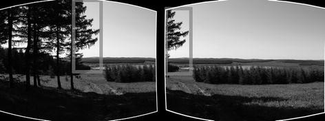
Found two photos overlap splicing
-
3.
Image Blending: After getting a good image stitching, you also need to overlap the image fusion process in order to achieve a seamless mosaic image. Main fusion methods are fade fusion method, finding the minimum energy path method, and multi-resolution spline fusion method, as shown in Fig. 13.
-
4.
Reprojection Transformation: According to the orientation of the viewpoint, calculated part of the image should be displayed, and in other beneficial OpenGL graphics library, this step can be done automatically, as shown in Fig. 14.
Fig. 14 
Reprojection transformation


5.3 Experiment and Results
In this chapter, the software used is Pano2VR, Object2VR, both three-dimensional panorama technology software is the embodiment of the three-dimensional static picture panorama technology. When a digital camera’s focal length is 35 mm, a 360° panoramic image normally takes 7–9 photos. When the focal length is 105 mm, a 360° panoramic image generally requires 24 photos, the focal length set at 35 mm.
In this chapter, the three-dimensional virtual scene panorama generation method based on panoramic images for authentication is discussed. Experimental images using a digital camera ecotourism in Hainan as photos of the scene, the same layer adjacent to the angle of rotation between the two pictures 30° between the upper and lower image rotation angle is 60°. Figure 15 is a computer after shooting a cylindrical panoramic image stitching process.

Panoramic images of cylinder
The panorama projection transformation is shown in Fig. 16. Panorama fusion is shown in Fig. 17. The experimental results show that large numbers of images, this study used the virtual scene generation method can generate cylindrical panoramic image, such as spherical panoramas, photos, high precision registration method, fusion method can achieve better coherence smooth transition between images, with good visual effect.

Reprojection

Fused panorama
6 Conclusion
Hainan has a unique natural environment, vast territory, and abundant resources. To effectively protect the ecological environment and the tropical island resources in Hainan ecotourism activities, the image-based 3D virtual scene can be reproduced in the field of ecotourism attractions roaming to achieve interactive tour feature. This method has been successfully applied to the ecotourism attractions of Hainan virtual panoramic display by a 360° panorama way to achieve ecotourism attractions of Hainan 3D virtual panorama roaming. Because it reproduces the real three-dimensional virtual scene, it has good travel Website interactivity and realism, thus greatly increasing the visibility and scenic spots in Hainan Ecological Website hits.
References
Zhang, X., Li, L.: Panoramic puzzles technology research and application. Graph., Images 8, 34–37 (2011)
Liu, D.: 3D virtual scene generation image and visualization. Syst. Simul. 17(1), 73–75 (2005)
Were, Y.: Resonance VRML-based virtual scene roaming implementation. Comput. Eng. Design 29(14), 3748–3751 (2008)
Liu, S., Gu, Y.: 3D build efficient virtual scene. Comput. Eng. Design 27(2), 303–306 (2006)
Li, Z.: Domestic and foreign research status of virtual reality technology. Liaoning Tech. Univ. Nat. Sci. Ed. 23(2), 238–240 (2004)
Gong, Y., Pu, X., Zhang, X.: Virtual scene roaming technology and system realization. Comput. Eng. Appl. 43(15), 89–91 (2007)
Jun, H., Zhou, J.: 3D virtual scene dynamic interactive technology research. Comput. Eng. Sci. 29(7), 55–57 (2007)
Xu, L., Jiang, Y.: Roaming the virtual scene modeling and implementation. Syst. Simul. 18(1), 120–124 (2006)
Xu, H., Wang, P., Wang, G., et al.: Panoramic jigsaw. Implementation Techn. 30(4), 417–422 (2004)
Wu, Q., Zhou, D., Caixuan, P.: Based on image sequences and roaming virtual scene reconstruction. Chin. J. Image Graph. 11(1), 113–118 (2006)
Wu, F., Zhang, X.: OpenInventor single image-based three-dimensional reconstruction application. Shanghai Electr. Inst. 12(3), 216–219 (2009)
Liu, G., Peng, Q., Bao, H.: Review and prospect of image-based modeling. J. Comput. Aided Design Comput. Graph. 17(1), 18–27 (2005)
Levoy, M., Hanrahan, P.: Light field rendering. Proceedings of the ACM SIGGRAPH, pp. 31–42. ACM, New York (1996)
Lv, X.: Based on interest points matching panorama stitching algorithm. Comput. Program. Skills Maintenance (16) (2011)
Guo, C., Cao, F.: Dimensional panorama technology introduced in the area of application. Geospatial Inf. (2) (2009)
Huang, J.: Dimensional digital technology in the museum website application. Digital Technol. Appl. (9) (2011)
Acknowledgments
This study was supported by the Hainan Natural Science Foundation (No: 612121, 612126), supported by the key Science and Technology Projects of Haikou City in 2010 (No: 2012-017) and was supported by disciplines project of Hainan Normal University expressed his thanks in this together.
Author information
Authors and Affiliations
Corresponding author
Editor information
Editors and Affiliations
Rights and permissions
Copyright information
© 2014 Springer International Publishing Switzerland
About this chapter
Cite this chapter
Feng, Jp., Wu, Lh., Ma, SQ. (2014). Research of 3D Virtual Scene Generation and Visualization Based on Images. In: Cao, BY., Ma, SQ., Cao, Hh. (eds) Ecosystem Assessment and Fuzzy Systems Management. Advances in Intelligent Systems and Computing, vol 254. Springer, Cham. https://doi.org/10.1007/978-3-319-03449-2_34
Download citation
DOI: https://doi.org/10.1007/978-3-319-03449-2_34
Published:
Publisher Name: Springer, Cham
Print ISBN: 978-3-319-03448-5
Online ISBN: 978-3-319-03449-2
eBook Packages: EngineeringEngineering (R0)