
Abstract
In this chapter, the state-of-the-arts developments of renewable energy are reviewed in respect to the installed power and market share, where wind power and photovoltaic power generation are the main focuses due to the fast growing speed and large share of installed capacity. Some basic principles of operation, mission profiles, as well as power electronics solutions and corresponding controls are discussed respectively in the case of wind power and photovoltaic power systems. Finally a few development trends for renewable energy conversions are also given from a power electronics point of view. It is concluded that as the quick development of renewable energy, wind power and PV power both show great potential to be largely integrated into the power grid. Power electronics is playing essential role in both of the systems to achieve more controllable, efficient, and reliable energy production—which is crucial for the cost reduction and spread use of renewable energies, because their fluctuated and unpredicted features are un-preferred for the operation of the power grid. Meanwhile there are also some emerging challenges and considerations in the renewable energy conversion system, calling for more advanced controls as well as configurations of power electronics converter.
Access provided by Autonomous University of Puebla. Download chapter PDF
Keywords
These keywords were added by machine and not by the authors. This process is experimental and the keywords may be updated as the learning algorithm improves.
Due to the shortage of inexhaustible resources and environmental problems caused by the emissions, the traditional power generations which are based on fossil fuel are generally considered to be unsustainable in the long term. As a result, many efforts are made worldwide and lots of countries have being introducing more renewable energies such as wind power, solar photovoltaic (PV) power, hydropower, biomass power, and ocean power, etc. into their electric grids [1–3]. The installed capacity of the renewable energy is growing so fast in the last decade—by 2012 the worldwide non-hydro power generation based on renewables has exceeded 480 Giga Watts (GW), which supplies 5.2 % of the global electricity consumption and accounts for almost half of the newly established generation capacity [3].
Among various renewable energy sources, the hydro power had a large installation in the past and nowadays accounts for the largest share of 67 % in renewables capacity. However, due to the special requirements for locations with river/lake resources, the worldwide growth of hydro power nowadays is very slow and it is considered to be close to the capacity limit. Differently, with fewer requirements for the locations, broader distribution of resources, fewer impacts of the environment, and more untapped capacities, wind power and solar power seems to be more promising to be largely utilized in the future.
The accumulated capacity of different renewables without hydro power by 2012 is shown in Fig. 1 [3]. It can be clearly seen that the wind power and solar PV have already accounted for 80 % of the total power production by non-hydro renewables. Moreover, among the major renewable energy technologies, the worldwide wind and PV power generation achieved the fastest growth rate at 25 and 60 % respectively in the last five years, as indicated in Fig. 2. As two extreme examples, by 2012 Denmark and Italy have more than 30 and 5.6 % of their electricity production covered by wind and solar PV, respectively, meanwhile some other countries like Germany, U.S., Spain and China are catching up and have also shown promising growth. Therefore these two renewables will be the main focus in this chapter in order to describe the technology enabling its grid interconnection including power electronics and system control.

Accumulated capacity share of different renewables by 2012 (480 GW total installed capacity without hydro-power) [3]

Worldwide growth rate of installed capacity for different renewable technologies in 2012 and between 2007 and 2012 [3]
1 Status of Wind Power and Photovoltaic Generation
1.1 Wind Power
The cumulative wind power capacity globally from 1999 to 2020 is shown in Fig. 3 [3], and it can be seen that the wind power has grown to a capacity of 283 GW with around 45 GW installed only in 2012, which accounted for 39 % of newly added renewable power capacity. Generally the wind power grows more significantly than any other renewables in many countries, and right now it is no longer an ancillary but an important player in the modem energy supply system.

Cumulative installed wind power capacity from 1996 to 2012 worldwide [1]
In respect to the markets and manufacturers, U.S. is the largest market with over 13.1 GW capacity installed in 2012, together with China (13 GW) and EU (11.9 GW) sharing around 87 % of the global market. The Danish company Vestas first gives out the first position among the biggest manufacturers since 2000, while GE takes over the top position due to the strong market of U.S. in 2012. Figure 4 summarizes the worldwide top suppliers of wind turbines in 2012. It can be seen that there are four Chinese companies in the Top 10 manufacturers with a total market share of 16.6 %, which is a significant drop compared to the 26 % in 2011 [3].

Distribution of wind turbine market share by manufacturers in 2012 (total capacity of 45 GW) [3]
1.2 Photovoltaic Power
The development of solar photovoltaic (PV) power has also been progressive especially in the recent five years. By 2012 it has already accounted for 26 % of newly added renewables and has reached the 100 GW milestone of capacity. This number makes PV power the third largest renewable energy source in terms of capacity after hydro and wind power. Figure 5 shows the cumulative PV installed capacity from 1996 to 2012, a boost of growing can be clearly observed after 2009.

Cumulative installed PV capacity from 1996 to 2012 [3]
Different from wind power, Germany and Italy are the top two markets in respect to PV power, with over 7.6 and 3.8 GW installed respectively in 2012. The PV markets in 2012 by different countries are summarized in Fig. 6, where it is can be seen that the Europe still dominates the PV markets and accounts for 70 % of the global PV capacity. The U.S., China, and Japan are also important markets with around 7 % market share each by 2012.

PV markets shared by different countries in 2012 (total 29 GW capacity) [3]
2 Wind Power Generation
The power conversion stages for a typical wind turbine system are shown in Fig. 7, in which the wind energy captured from the nature is the input, and electrical power injected into the power grid is the output. There are mainly two types of energy conversion in the system, including both the mechanical and electrical parts.

Converting wind power into electrical power in a wind turbine system
As illustrated in Fig. 7, the wind turbine first captures the wind power by means of aero-dynamical blades and converts it to mechanical power in the rotating shaft of the generator. For typical multi-MW wind turbines, the rotational speed of turbine rotor is relative low and normally ranges in 5–16 rpm, which may result in bulky generator solutions and increase the installation cost. Therefore a gearbox in Fig. 7 may be needed to convert the mechanical power to the one with higher-speed and lower-torque, which will contribute to the size and weight reduction of the generator [4].
The electrical power produced by the generator also needs to be regulated in order to be injected into the power grid. As shown in Fig. 7, a power electronics converter is normally used which enables certain controllability of the electrical power in the system. Finally a transformer is generally used by manufacturers to boost the voltage level, achieving more efficient power transmission in the power grid. Consequently, the wind energy is refined by the wind turbine system to more controlled and regulated electrical power.
2.1 Basic Operation of Wind Turbine System
In a wind turbine system there are a few control variables to ensure a reliable, controllable, and efficient power production. It is essential first to be able to limit the mechanical power generated by wind turbines under higher wind speeds in order to prevent overloading. The power limitation is done either by Stall Control (the blade position is fixed but stall of the wind appears along the blade), Active Stall Control (The blade angle is adjusted in order to create stall along the blades) or Pitch Control (the blades are turned out of the wind). The characteristics of the output mechanical power using the three types of power limitation methods are compared in Fig. 8 [5]. It can be clearly seen that the pitch control approach can achieve the best power limitation performance and it has already become the dominant technology solution in the newly established wind turbines.

Power limitations by different methods (Passive stall is based on fixed speed operation) [5]
Another control variable of the wind turbines is the rotational speed of turbine rotor. In the past this control freedom is not utilized and the rotational speed is fixed during the whole operation range of wind speeds. Although the fixed speed wind turbines have the advantages of simple, robust and low cost of the electrical parts, the drawbacks are even more significant like the uncontrollable electrical power, large mechanical stress during wind gusts and unsatisfactory power quality of output.
Nowadays the variable speed wind turbines are widely used in order to achieve better aerodynamic efficiency and also overall control performance. By introducing the variable speed operation, it is possible to continuously adapt the rotational speed of the wind turbine to the wind speed, in such a way that the tip speed ratio is kept constant to achieve the maximum power coefficient of the blades and thereby maximum power extracting efficiency of wind turbine. The power variations in wind will be absorbed by changing rotational speed of the rotor, the mechanical stress and acoustical noise can be thereby reduced. Additionally, the power converters used for speed adjustment can also provide higher quality electrical power in order to fulfill the higher technical demands imposed by the grid operators. This feature is becoming a determining factor in the development of the modern wind power technologies [4].
2.2 Mission Profile for Wind Turbine System
2.2.1 Wind Speed Profiles
As the input of the whole wind turbine system, the wind energy quantified by the wind speed is an important factor that can determine the design, control, maintenance, energy yield and also the cost of the whole system. A field recorded 1-year wind speeds is illustrated in Fig. 9 [6], which is based on 3 h averaged at 80 m hub height, and it was designated for the wind farm located near Thyborøn, Denmark with latitude 56.71° and longitude 8.20°. The chosen hub wind speed belongs to the wind class IEC I with average wind speed of 8.5–10 m/s. It can be seen that the wind speed fluctuates largely from 0 up to 28 m/s. Without proper controls of the mechanical and electrical parts, this significant fluctuation may be transferred to the grid and cause grid stability problems. Moreover the components in the system may suffer from largely cyclical loadings which may quickly trigger reliability problems [7–11]. As a result, the roughness and fluctuation of wind speeds should be carefully taken into account in the control and design of the power electronics converter [12].

One year mission profile of wind speed and ambient temperature from a wind farm of Denmark (3-h averaged)
2.2.2 Requirements for Modern Wind Power Converter
As the quick development of capacity and technology in the wind power generation, the power electronics converter is becoming more essential. On the other hand, the power electronics converters also need to satisfy much tougher requirements than ever before. These requirements can be generally characterized as shown in Fig. 10 [13, 14]:
-
(A)
General requirements
For the generator side, the current flowing in the generator rotor or stator should be regulated to control the electromagnetic torque, not only for maximizing the extracted power from the wind turbines, but also for the energy balancing in case of dynamics due to the inertia mismatch between mechanical and electrical power conversions. For the grid side, the converter must emulate the behaviors of conventional power plants regardless of the wind speed. This means it should help to maintain the frequency as well as voltage amplitude of the grid, and also withstand the grid faults or even contribute the faults recovery [4, 15–19].
-
(B)
Special considerations
Due to relative large power capacity, the failures of wind power conversion system may impose strong impacts to grid stability and result in high cost to repair, thereby the reliability performance is especially emphasized. Because of high power capacity, the voltage level of generator may need to be boosted up to facilitate the power transmission, thus step-up transformer are normally required in wind turbine system. Furthermore, because the space is limited in the nacelle or tower of wind turbines, the power density and cooling ability are crucial performance for power converter. Finally because of the mismatching power inertia between the turbine and grid, energy storage and balancing is an important issue and may result in extra cost of the system.

Demands for modern wind power converters
2.3 Wind Turbine Concepts and Topologies
2.3.1 Popular Wind Turbine Concepts
The development of the wind turbine technology has been steady for the last 35 years [4, 5, 13, 14]. Depending on the types of generator, power electronics, speed controllability and the way in which the aerodynamic power is limited, the wind turbine designs can generally be categorized into several concepts [5, 20]. In these wind turbine concepts the power electronics play quite different role and has various power rating coverage of the system. Up until now the configuration of Doubly Fed Induction Generator (DFIG) equipped with partial-scale power converter is dominating on the market, but in very near future the configuration with Synchronous Generator (SG) and full-scale power converter is expected to take over to be the dominant solution [4, 14]. In the following these two state-of-the-art wind turbine concepts are going to be introduced.
-
(A)
Doubly-Fed Induction-Generator with partial-scale power converter
This wind turbine concept is the most adopted solution nowadays and it has been used extensively since 2000s. As shown in Fig. 11, a power electronics converter is adopted in conjunction with the Doubly-Fed Induction Generator (DFIG). The stator windings of DFIG are directly connected to the power grid, while the rotor windings are connected to the power grid by the converter with normally 30 % capacity of the wind turbine [21–25]. In this concept, the frequency and the current in the rotor can be flexible regulated and thus the variable speed range can be extended to a satisfactory level. The smaller converter capacity makes this concept attractive seen from a cost point of view. However, its main drawbacks are the use of slip-rings and the insufficient power controllability in the case of grid faults—these disadvantages may comprise the reliability and may be difficult to completely satisfy the future grid requirements as claimed in [26, 27].
Fig. 11 
Variable speed wind turbine with partial-scale power converter and a doubly fed induction generator
-
(B)
Asynchronous/synchronous generator with full-scale power converter
The second important concept that is popular for the newly developed and installed wind turbines is shown in Fig. 12. It introduces a full-scale power converter to interconnect the power grid and stator windings of generator, thus all the generated power from the wind turbine can be regulated. The Asynchronous Generator, Wound Rotor Synchronous Generator (WRSG) or Permanent Magnet Synchronous Generator (PMSG) have been reported to be used. The elimination of slip rings, simpler or even eliminated gearbox, full power and speed controllability as well as better grid support ability are the main advantages compared to the DFIG based concept. However, the more stressed and expensive power electronic components as well as the higher power losses in the converter are the main drawbacks of this concept.
Fig. 12 
Variable speed wind turbine with full-scale power converter


2.3.2 Power Converters for Wind Turbines
-
(A)
Two-level power converter
The Two-Level Pulse-Width-Modulation Voltage-Source-Converter (2L-PWM-VSC) is the most used converter topology so far for the DIFG based wind turbine concept as the power rating requirement for the converter is limited. Normally, two 2L-PWM-VSCs are configured in a back-to-back structure in the wind turbine system, as shown in Fig. 13 which is called 2L-BTB for convenience. A technical advantage of the 2L-BTB solution is the full power controllability (4-quadrant operation) with a relatively simple structure and few components, which contribute to well-proven robust/reliable performances as well as advantage of cost.
Fig. 13 
Two-level back-to-back voltage source converter for wind turbine (2L-BTB)
As for the full scale converter based concept, the converter needs to carry all the generated power by wind turbines e.g. up to 10 MW, the 2L-BTB converter topology at this power level may suffer from large switching loss and many devices may need to be connected in parallel, also the cabling in case of low voltage level can be a great design/physical challenge. Consequently, it is becoming more and more difficult for a single 2L-BTB topology to achieve acceptable performance for the full-scale wind power converter, even though having the cost advantage.
-
(B)
Multilevel power converter
With the abilities to achieve higher voltage and power level, multi-level converters may become more preferred candidates in the full-scale converter based concept [26–28]. The Three-level Neutral Point diode Clamped topology (3L-NPC) is one of the most commercialized multi-level topologies on the market. Similar to the 2L-BTB, it is usually configured as a back-to-back structure in the wind power application, as shown in Fig. 14, which is called 3L-NPC BTB for convenience. The 3L-BTB solution achieves one more output voltage level and less dv/dt stress compared to the counterpart of 2L-BTB, thus it is possible to convert the power at medium voltage with lower current, less paralleled devices, and smaller filter size. The mid-point voltage fluctuation of the DC-bus can be a drawback of the 3L-NPC BTB. This problem has been extensively researched and it is considered to be improved by the controlling of redundant switching states [29–31]. However, it is found that the loss distribution is unequal between the outer and inner switching devices in a switching arm [32–34], and this problem might lead to a de-rated power capacity, when it is practically used.
Fig. 14 
Three-level neutral point clamped back-to-back converter for wind turbine (3L-NPC BTB)
-
(C)
Multi-cell converter
In order to handle the fast growing power capacity, some multi-cell converter configurations (i.e. parallel/series connection of converter cells) are developed and widely adopted by the industry.
Figure 15a shows a multi-cell solution adopted by Gamesa in the 4.5 MW wind turbines [35], which have 2L-BTB single-cell converters paralleled both on the generator side and on the grid side. Siemens also introduce the similar solution in their best-selling multi-MW wind turbines, as indicated in Fig. 15b [36]. The standard and proven low voltage converter cells as well as redundant and modular characteristics are the main advantages. This converter configuration is the state-of-the-art solution in the industry for the wind turbines with power level higher than 3 MW.
Fig. 15 
Multi-cell converter with paralleled converter cells (MC-PCC). a Variant 1, b Variant 2
Another multi-cell configuration shares the similar idea with the next generation traction converters [37, 38], and is also proposed in the European UNIFLEX-PM Project [39], as shown in Fig. 16. It is based on a structure of back-to-back Cascaded H-bridge converter, with galvanic insulated DC/DC converters as interface. The DC/DC converters have Medium Frequency Transformer (MFT) operating at several kHz up to dozens of kHz, thereby the transformer size can be significantly reduced in both weight and volume. Moreover, because of the cascaded structure, it can be directly connected to the distribution power grid (10–33 kV) with high output voltage quality, filter-less design, and redundant ability [35, 36]. Figure 17 shows another configuration sharing the similar idea with some of the emerging converters used for High Voltage Direct Current (HVDC) Transmission [40, 41]. It is also based on a back-to-back structure with cascaded DC/AC converter cells. One advantage of this configuration is the easily scalable voltage/power capability; therefore it can achieve very high power conversion at dozens of kV with good modularity and redundancy.
Fig. 16 
Cascaded H-bridge converter with medium frequency transformer for wind turbine system (CHB-MFT)
Fig. 17 
Modular multilevel converters for wind turbine (MMC)


2.4 General Control Targets of Wind Turbine System
Controlling a wind turbine involves both fast and slow control dynamics [42–50], as indicated in Fig. 18, where a control structure for a wind turbine system including turbine, generator, filter and converter are indicated. Generally the power flowing in and out of the generation system has to be managed. The generated power by the turbines should be controlled by means of mechanical parts (e.g. pitch angle of blades, yawing system, etc.). Meanwhile, the whole system has to follow the power production commands given by Distribution/Transmission System Operators (DSO/TSO).

General control structure for modern wind turbines
More advanced features of the control system may be taken into account like the maximization of the generated power, ride through operation of the grid faults and providing grid supporting functions in both normal and abnormal operations of power grid. In the variable speed wind turbine concept, the current in the generator will typically be changed by controlling the generator side converter, and thereby the rotational speed of turbine can be adjusted to achieve maximum power production. In respect to the operation under grid faults, coordinated control of several subsystems in the wind turbine like the generator/grid side converters, breaking chopper/crowbar, pitch angle controller is necessary.
Finally, the basic controls like current regulation, DC bus stabilization and the grid synchronization have to be quickly performed by the power converter, where the Proportional-Integral (PI) controller and Proportional-Resonant (PR) controllers are typically used.
As an example, the control methods for a DFIG based wind turbine system are shown in Fig. 19. Below maximum power production the wind turbine will typically vary the rotational speed proportional with the wind speed and keep the pitch angle θ fixed. At very low wind speed the rotational speed will be fixed at the maximum allowable slip in order prevent over voltage of generator output. A pitch angle controller is used to limit the power when the turbine output above the nominal power. The total electrical power of the wind turbine system is regulated by controlling the DFIG through the rotor-side converter. The control strategy of the grid-side converter is simply just to keep the dc-link voltage fixed. It is noted that a trend is to use a crowbar connected to the rotor of DFIG in order to improve the control performance under grid faults.

Control of a wind turbine with doubly-fed induction generator
Another example for the control structure used for full-scale converter based wind turbine concept is shown in Fig. 20. An advantage of this turbine system is that the dc-link performs some kind of control decoupling between the turbine and the grid. The dc-link will also give an option for the wind turbines to be connected with energy storage units, which can better manage the active power flow injected into the power grid—this feature will further improve the grid supporting abilities of the wind turbines. The generated active power of the wind turbine system is controlled by the generator side converter, while the reactive power is controlled by the grid side converter. It is noted that a DC chopper is normally introduced to prevent over voltage of DC link in case of grid faults, when the extra turbine power needs to be dissipated as the sudden drop of grid voltage.

Control of active and reactive power in a wind turbine with multi-pole synchronous generator
3 Photovoltaic Power Generation
Due to the cost reduction of Photovoltaic (PV) modules and the development of PV cell technology, the PV power generation has been becoming dominant in the renewable energy supplies of some countries [57–61]. It is expected that the cost of PV technology will continue declining, which will also make the grid-connected PV systems competitive compared to other renewable energy systems.
A grid-connected PV power system has to efficiently and reliably transfer and convert the solar energy, which is highly dependent on the environmental conditions (i.e. irradiance level and ambient temperature). Power electronics systems, known as PV inverters, together with advanced and intelligent control strategies, are able to enable an effective transferring of the generated PV energy to the grid [4, 5, 58, 60]. Hence, the basic functions of a PV conversion system include: maximum power extraction from PV panels in response to the environmental dependency, grid synchronization, compliance of grid connection requirements, anti-islanding, and etc. [49, 50, 62–64].
In this part, a brief introduction of the PV cell development and the characteristics of solar PV cell are presented firstly, followed by the mission profiles and the demands for PV power conversion systems. An overview of the advanced PV inverters for grid-connected PV systems is demonstrated in Sect. 3.3. Finally, the general control targets of grid-connected PV power conversion systems are given in Sect. 3.4 with some basic control examples. Advanced control strategies for PV systems are detailed in another chapter—Advanced Control of Photovoltaic and Wind Turbines Power Systems.
3.1 Photovoltaic Cell Technology and Characteristics
As the core and source of a PV power conversion system, PV panels are typically connected to the DC-AC converter. Depending on the voltage level, a DC–DC stage may be required to boost up the DC-link voltage to an acceptable level of the PV inverter. Similar to this concept, a PV panel/module is an assembly of many PV cells connected in series (increased output voltage) and in parallel (increased output current), as it is shown in Fig. 21a.

A PV panel: a from solar cells to panel, b electrical model
Various materials with varying efficiencies and costs can be used to make PV cells. At present, the commonly used materials for PV cells include mono- and poly-crystalline silicon. Those crystalline-silicon-based PV cells can achieve an efficiency of 11–15 % [64, 65]. Another PV cell technology is called thin-film technology, which reduces the amount of required material to create a PV cell. Thin-film PV cells are typically based on cadmium telluride, copper indium gallium selenide, and amorphous silicon [65, 66]. However, the thin-film based PV cells have a relative lower efficiency compared to the crystalline-silicon-based PV cells [64].
The operating principle of all these PV technologies is based on the photovoltaic effect. When a PV cell is exposed to the sunlight, the photons of the semiconductor material are excited, and then jump to the conduction band and become free. Thus, an electromotive force is generated. When the PV cell is connected into a closed loop, the freed electrons will introduce a DC current and the solar energy is converted to electric energy. Hence, the current produced by a PV cell is highly dependent on the solar irradiance level and the ambient temperature. An electrical circuit shown in Fig. 21b can be used to model the characteristics of a PV module or cell. This model has a photo-current source, i ph , in parallel with a diode, a shunt resistance R p , and a series resistance R s .
As it has been discussed in the previous paragraph, the generated current of a PV panel, and thus the output power, are significantly affected by the solar irradiance level and the ambient temperature. According to Fig. 21b, the electrical characteristics (I-V and P-V characteristics) of a PV panel are non-linear and also varied with the ambient conditions, as can be observed in Fig. 22. Due to the properties of non-linearity and environmental dependency of the PV panel, a Maximum Power Point Tracking (MPPT) algorithm is necessary to ensure that the solar energy is captured and converted as much as possible—also for the sake of reduction of cost of energy.

I-V and P-V characteristics of a PV panel: a different solar irradiance levels at 25 °C, b different ambient temperatures at 1000 W/m2
It can be seen in Fig. 22 that the power curve of a PV panel is of “hill” form under a given condition. Thus, the P-V curve can be divided into three segments: (a) climbing—a positive dp/dv, when the PV panel is working as a constant current source, (b) going-down—a negative dp/dv, and (c) the-top—dp/dv = 0, which corresponds to the Maximum Power Point (MPP) for a given ambient condition (e.g. 25 °C, 1000 W/m2). Many proposed MPPT algorithms are based this “hill” characteristic of a PV panel (when the MPP is reached, dp/dv = 0), such as the Perturb-and-Observe (P&O) method and the Incremental Conductance (INC) method [67, 68]. The output of the MPPT control system (e.g. power, current or voltage) is the reference to be controlled by a DC–DC converter or directly a DC-AC inverter, depending on the configuration of the PV system.
However, it should be pointed out that the characteristics shown in Fig. 22 are only for an individual PV panel or module. If many PV panels are connected in series (PV string) or in parallel (PV array) to increase the output power, the MPPs may be different because of panel mismatch. Moreover, the partial shading of the panels increases the MPPT difficulty [66]. Thus, a robust MPPT control algorithm is crucial for PV systems in order to maximize the energy yield of PV strings/arrays with mismatch and partial shading issues.
3.2 Mission Profiles for Photovoltaic Conversion Systems
3.2.1 Solar Irradiance and Ambient Temperature Profiles
Since the output power of a PV panel is significantly dependent on the environmental conditions, the knowledge of mission profiles, including solar irradiance level and ambient temperature has become of high importance for the design, control and operation of a PV conversion system. With the accumulation of field experiences and the introduction of more and more real-time monitoring systems, better mission profile data is expected to be available in various kinds of power electronic systems (e.g. PV inverters) [69]. This offers the possibilities to predict the lifetime of a PV inverter and the energy production of a PV system [69, 70].
Figure 23 shows yearly mission profiles for PV systems in Aalborg East, Denmark, from October 2011 to September 2012. The original recorded data has a sampling frequency of 5 Hz [73]. In Fig. 23, the data is resampled every 5 min. It can be observed from Fig. 23 that both the solar irradiance level and the ambient temperature vary significantly through a year. Those fluctuations require dedicated MPPT control systems in order to increase energy yield. Moreover, due to the intermittency, the resultant power, generated by a PV system and then transferred to the grid, may cause grid stability problems—especially when the global PV penetration is getting larger and larger. It is also found that the reliability of a power electronics system has a strong connection with the temperature loading on the power electronics devices [6, 70–72], which is affected by the mission profiles. Hence, different time-scale mission profiles may have an influence on the consumed lifetime of a power electronics system [6].

Yearly mission profiles from recorded data (5 min per sampling data) for PV systems: a solar irradiance level, b ambient temperature
Consequently, those aspects related to mission profiles have to be carefully taken into considerations in the control and design of the power electronics converters for PV systems. With the development of power electronics technology, the advancement of monitoring techniques, and also intelligent control strategies, further improvement of the lifetime and reduction of energy cost for a PV system can be achieved.
3.2.2 Requirements for PV Conversion Systems
Grid-connected PV systems are being developed very fast and will soon take a major part of electricity generation in some areas [59, 61]. In order to ensure a reliable and efficient transfer of solar energy to the grid, the power electronics converters (mainly PV inverters) have to comply with much tougher requirements than ever before. These requirements can be generally categorized into the following three parts as shown in Fig. 24.

General demands for the grid-connected PV power conversion system
-
(A)
General requirements
In the PV power conversion the power capacity is not as large as the wind power. Moreover the power inertia of PV output is compatible with the behavior of power grid, and as a result the requirements are less tough when compared to wind turbine systems.
For the PV side, the current or voltage of PV panels should be controlled in order to achieve maximum extracted solar energy. In view of this, a DC–DC converter is commonly used in PV power conversation systems to flexibly track the maximum power, which is strongly dependent on the mission profiles. In this case, the DC voltage should be maintained as a desirable value for the inverter during operation. For the grid side, the requirements are not as stringent as those in wind power systems, but normally the Total Harmonic Distortion (THD) of the output current must be restrained at a lower level (e.g. 5 %) [74]. While for large PV systems with higher power ratings (e.g. hundreds kW connected to medium voltage grid), the grid side also demands the PV inverter to stabilize the grid voltage by providing ancillary services. In response to grid faults, the PV inverters have to ride-through voltage faults, when a higher PV penetration level comes to reality [75–78]. Such requirements are expected to cover a wide range of PV applications [77, 78].
-
(B)
Special considerations
For PV technology the power capacity per generating unit is relative low but the cost of energy is relative high, as a result there are very strong demands for high efficiency power conversion in order to achieve acceptable price per produced kWh. On the other hand, transformerless PV inverters have gained increasing popularity in the European market (e.g. Germany and Spain) [49, 80] in order to further extend the conversion efficiency. However in this case the safety becomes a more crucial issue because of the lack of galvanic isolation in transformerless PV systems. Reduction of the potential leakage current is generally required [49].
Furthermore, similar to the wind power conversion systems, reliability is also important for power electronics based PV systems, and motivated by extending the total energy production (service time) and reducing the cost. Finally, because of exposure or smaller housing chamber, the PV converter system must be more temperature insensitive, which is beneficial for the reliability performance.
3.3 Photovoltaic Concepts and Topologies
Most of the demands mentioned above for PV systems are performed by the power electronics systems, i.e. PV inverters. Hence, an overview of the basic configurations for grid-connected PV systems is given in the following. This section includes dominant PV inverter concepts, covering a wide range of PV applications, and transformerless inverter topologies, which can achieve high efficiency.
3.3.1 PV System Configuration Concepts
Unlike the wind power technology, the solar PV produces much lower power per generating unit (e.g. individual PV panel or PV string), and thereby the PV system is normally composed of many panels connected in parallel and/or series to increase the output power within an acceptable range. According to the state-of-the-art technologies, there are mainly four concepts [63, 64] to organize and deliver the PV power to the public grid, as shown in Fig. 25, each of the concept consists of a series of PV panels or strings and a couple of power electronics converters (DC–DC converters and DC-AC inverters) configured in different structures. Depending on the output voltage level, a boost converter may be required by the string and multi-string inverters.

Different grid-connected PV inverter structures: a small system b residential c commercial/residential d commercial/utility scale PV plants
-
(A)
Central inverter
For this inverter concept, PV panels are arranged in paralleled strings, and are connected to one common central inverter, as shown in Fig. 25d. The central inverter, typically three-phase, is the most widely alternative for large-scale or utility-scale PV power plants, which have high power ratings (e.g. 750 kW SMA Central Inverter [81]). Such inverters have to be equipped with ancillary service functions, like fault ride-through and reactive power injection due to the high power ratings. Adoption of a central inverter is the simplest way to concentrate a large PV plant with low construction cost. However, the disadvantages of this configuration are also significant and they are listed as follows [63]:
-
need for high DC-link voltage (550–850 V) and very long DC cables between PV strings and the central inverter,
-
power losses due to a common MPPT applied to the central inverter,
-
power loss due to module mismatch,
-
losses in the string diodes (blocking diodes), and
-
reliability of the whole system depends only on one inverter.
As the capacity of the PV power plants continues growing, various inverter topologies are in those applications to handle high power and high voltage PV systems. Two-level voltage source inverters are currently the most optimal solution for central inverters of large-scale PV power plants. Other multi-level inverters, like three-phase three-level neutral point clamped inverter, which is typically used in wind power systems, can also be adopted in large PV power plants due to the capability to surpass classic semiconductor voltage blocking limits.
-
-
(B)
String inverter
As shown in Fig. 25b, the string inverter concept was first introduced into the European market in 1995. It is based on a modular concept, where PV strings are made up of series-connected PV panels, and are connected to separate string inverters (single- or three-phase). Then, the string inverters are paralleled and connected to the grid. If the PV string terminal voltage is high enough—no voltage boosting is necessary (single-stage), an improvement of the overall system efficiency can be achieved. Moreover, fewer PV panels for each string can also be used, but then a DC–DC boost converter, a DC-AC-DC high-frequency transformer-based converter, or a line frequency transformer is required as the boosting stage, comprising the efficiency performance. The advantages compared to the central inverter are as follows [63]:
-
no losses in string diodes (no diodes needed),
-
individual MPPT for each string,
-
better yield, due to separate MPPTs,
-
lower price due to the mass production.
Depending on the grid connection standards, the transformer may be removed in order to further increase the efficiency in some countries (Germany and Spain) where galvanic isolation is not required. This makes the string inverter to be transformerless system, and thus specific design of transformerless inverters and modulation schemes are required in order to eliminate the leakage ground currents due to the parasitic capacitance between the PV panels and the ground [49, 76, 80].
-
-
(C)
Multi-string inverter
Multi-string inverters have recently introduced on the PV market. They are an intermediate solution between string inverters and central inverters. A multi-string inverter, shown in Fig. 25c, combines the advantages of both string-inverters (high energy production due to individual MPPT control) and central-inverters (low cost), by having many DC–DC converters with individual MPPTs, which feed energy into a common DC-AC inverter. In this way, no matter what the nominal data, string size, PV module technology (e.g. crystalline or thin film), orientation, inclination or weather conditions (e.g. partial shading) of different PV strings are, they can be connected to one common grid-connected inverter [63, 82]. The multi-string concept is a flexible solution, having a high overall efficiency of power extraction, due to the fact that each PV string is individually controlled. The major feature of a multi-string inverter is the multiple DC–DC stages connected in parallel to the DC-link. Thus, transformerless PV inverter technology can also be adopted in the multi-string inverter systems. As mentioned above, the leakage currents should be taken care of during the inverter design and operation.
-
(D)
Module inverter
An AC module is made up with an individual solar panel connected to the grid through its own inverter, as shown in Fig. 25a. The advantage of this configuration is that there are no mismatch losses, due to the fact that every single solar panel has its own inverter and MPPT control, thus maximizing the power production. The power extraction is much better optimized than in the case of string inverters. One other advantage is the modular structure, which simplifies the modification and maintenance of the whole system because of its “plug & play” characteristic. One disadvantage is that the price per watt is still higher than in the previous cases [63]. Moreover, due to the low power ratings of PV modules, large voltage amplification units for grid connection are required, and thus making the whole system difficult to achieve high efficiency. In view of those demerits, this inverter configuration has not been widely adopted even for small or medium-scale PV systems.
3.3.2 Transformerless PV Inverter Topologies
To achieve high efficiency, transformerless inverters are introduced to string-inverters and multi-string inverters, where single-phase configurations are more common. As aforementioned, due to the lack of galvanic isolation, leakage currents will appear between the PV panels and the ground and will cause safety issues. Thus, the transformerless inverters are required to reduce the leakage currents either by redesigning the topology or by modifying the modulation schemes. In the following, different single-phase transformerless PV-inverter technologies are discussed.
-
(A)
H-Bridge topology with bipolar PWM
The H-Bridge inverter (Fig. 26) is a well-known topology and it is almost the standard solution for the single-phase DC-AC power conversion. It has been widely used in the motor drives and UPS applications. However, in the case of the transformerless configuration for PV system, the PWM modulation strategies should be carefully selected, because some popular modulation methods like unipolar PWM may introduce abrupt change of the common mode voltage (high dv/dt) and thus leads to a large leakage current, which are in-preferable in transformerless PV systems and grid connection standards [49, 76]. The bipolar modulation scheme can be adopted in an H-Bridge transformerless inverter with effective elimination of leakage currents, but also with lower efficiency.
Fig. 26 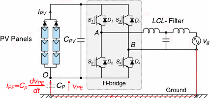
H-bridge transformerless topology for PV application (V PE common mode voltage, i PE leakage current)
In order to improve the common-mode behavior, meanwhile further to increase the efficiency, and to keep all the other merits given by the H- bridge inverter, some modified topologies are proposed in the PV application by adding bypass switches either on the DC side or on the AC side [76, 79, 80, 82–86], as it will be detailed in the following.
-
(B)
HERIC topology
The Highly Efficient and Reliable Inverter Concept (HERIC) [87] includes two extra switches (SD 5–SD 6) on the AC output of the inverter, as it is shown in Fig. 27.
Fig. 27 
HERIC transformerless topology for PV applications
The common-mode behavior of the HERIC topology is similar to the H-Bridge converter with bipolar PWM, where the voltage to ground of the PV array terminals will only have a sinusoidal shape, while the same high efficiency can be also achieved as the H-bridge converter with unipolar PWM. Therefore, the HERIC topology is more suitable for transformer-less PV system in terms of efficiency (up to 98 % reported) and is widely used for the power range of 2.5–5 kW for single-phase applications [88].
-
(C)
H5 inverter
Another suitable topology for the transformer less PV power conversion is called H5 converter, as shown in Fig. 28 [89], which is patented and used by SMA in many of their transformerless inverters. This topology introduces an extra switch (SD 5) on the DC side of H-bridge converter, and it can disconnect the PV panels from the grid during the zero voltage states. Thus, the reduction of leakage currents is achieved.
Fig. 28 
H5 transformerless topology for PV applications
Similar to the HERIC inverter, the common-mode behavior of the H5 topology is similar to the H-Bridge with bipolar PWM. The voltage to ground of the PV array terminals will only have a sinusoidal shape, while having the same high conversion efficiency as the H-Bridge with unipolar switching. Unipolar output voltage is achieved by disconnecting the PV array from the grid by using a method called DC decoupling.
-
(D)
H6 inverter
Another transformerless topology using the DC decoupling method is called the H6 converter [84, 85], which adds two extra switches and two extra diodes to the H-bridge topology as shown in Fig. 29.
Fig. 29 
H6 transformerless topology for PV applications
The common-mode behavior of the topology is similar to the HERIC and H5 topologies, since the voltage to ground of the PV array has only a sinusoidal shape and the frequency is the grid frequency. It is another suitable solution for transformerless PV systems, and several commercial products are available on the markets with the efficiency of up to 97 %.
-
(E)
Neutral Point Clamped topology
Besides the H-bridge based topologies, some half bridge solutions are also used in the PV system. The Neutral Point Clamped (NPC) topology shown in Fig. 30a was introduced some years ago in [90]. The voltage to ground measured at both PV array terminals is constant, this is due to the connection of the neutral line of the middle point of the DC-link that fixes the potential of the PV array to the grounded neutral.
Fig. 30 
Neutral Point Clamped transformerless topology for PV application a NPC half-bridge inverter b Conergy NPC inverter
The NPC topology is suitable for transformerless PV systems, since the voltage to ground is constant. The only drawback for the single-phase NPC topology is the high DC-link voltage, which has to be more than twice of the grid peak voltage; therefore a boost stage is normally required before the inverter, which will decrease the overall efficiency of the PV system.
A “variant” of the classical NPC topology is also popular in the PV application, as shown in Fig. 30b, which is called Conergy NPC converter [91]. The output voltage of the Conergy converter is clamped to the DC neutral point by a bidirectional switch, which is normally realized with two back-to-back IGBTs, as detailed in [92].


3.3.3 Central Inverter Topology for High Power PV Applications
Although single-phase configurations are more common for PV applications, some companies like SMA, Sunways, and Kaco are promoting the three-phase PV systems with central inverters for utility-scale applications [81, 88, 93]. For example, the Neuhardenberg solar power plant with a nominal output of 19.69 MWp in Germany uses Powador XP500-HV TL central inverters [93, 94]; the largest European thin-film PV power plant Equipped with 114 Sunny Central 900CP XT inverters from SMA, forming a PV plant of 128 MWp [95]. Those large PV power plants, rated over tens and even hundreds of MW, adopt many central inverters with the power rating of up to 900 kW. A typical large-scale PV power plant is shown in Fig. 31, where DC–DC converters are also used before the central inverters.

Typical large-scale PV power plant based on central inverters for utility applications
3.4 General Control Targets of Photovoltaic Systems
According to the demands for a grid-connected PV system shown in Fig. 24, and also the above discussions, the PV systems should be controlled to perform those functions reliably and efficiently. The variability of PV inverter topologies and system configurations (single- or two-stage) increases the control difficulty. Nonetheless, as it is shown in Fig. 32, the general control objectives for a grid-connected PV system are universal, including MPPT, DC-link control, grid synchronization, voltage/current control, anti-islanding protection, system condition monitoring (grid and PV panels), and ancillary services (especially for a high power PV system). With the increasing PV capacity, the power flowing-in and -out of PV systems has to be managed with other systems (e.g. energy storage systems). Thus, communications are necessary to perform this function. Meanwhile, the whole system has to follow the set-point commands given by Distribution/Transmission System Operators (DSO/TSO) for system stability concern.

General control structure of a grid-connected PV system
More advanced features of the control system, which are required in wind turbine systems, may be taken into consideration at high penetration level of PV systems. For instance, delta power production control, frequency control through active power, voltage control through reactive power, ride-through operation of the grid faults, and the provision of grid support in both normal and abnormal conditions to the grid, have been set for high power PV systems [4, 19, 20, 57, 78]. Some of those features are extended and coming into effectiveness for residential PV applications with low power ratings [75–77]. Typically, those features can be implemented in the outer loop of a cascaded dual-loop control system, which provides a current reference to shape the injected current [50, 76]. Regarding the operation under grid faults, since the PV systems have much lower physical inertia when compared to wind turbine systems, the power of a PV system during fault ride-through operation should be dispatched at least by: (a) modifying the MPPT control, (b) activating DC chopper to absorb power, and (c) managing power exchange between PV systems and the energy storage systems.
Consequently, the basic controls like current regulation (in the inner control loop), DC-link voltage stabilization, grid synchronization, and anti-islanding have to be quickly performed by the power converter.
Since single-phase PV systems are more commonly seen, an example of the control for a single-phase two-stage grid-connected PV system can be observed in Fig. 33, where the control system can be divided into two parts—the boost converter control and the inverter control. The boost converter is controlled to track the maximum power of the PV panels affected by the input solar irradiance level and ambient temperature. The inverter is controlled to maintain the DC-link voltage level. As it is shown in Fig. 32, the injected grid current is synchronized with the grid voltage using a phase-locked-loop system. The current controller is responsible for the injected current quality. The Proportional Resonant (PR), Resonant Control (RSC), Repetitive Controller (RC), and Deadbeat Controller (DB) can be adopted directly as the current controller, since they are capable to track sinusoidal signals without steady-state errors [49, 50, 76]. By applying the Park transformation (αβ → dq) leads to the possibility of Proportional Integral (PI) controllers to regulate the injected current with the help of an orthogonal signal generator. Furthermore, by introducing Harmonic Compensators (HC) for the controller and adding passive damping for the filter, an enhancement of the current controller tracking performance can be achieved [47, 50, 68, 76].

Basic control structure of a single-phase grid-connected PV system
Another example for the control structure used for three-phase PV systems is shown in Fig. 33. Unlike single-phase systems, the Clarke transform and the Park transform can be used in the control of three-phase systems. Hence, the control of a three-phase PV system can be implemented in the synchronous rotating reference frame (dq-control), in the stationary reference frame (αβ-control), and also in the natural reference frame (abc-control), where the three phase currents are controlled separately [50]. Similarly, for a two-stage system, the control can be divided into two parts. The first one is about the MPPT control by the boost converter. The second one is about the injected current control. In different reference frames, the above mentioned current controllers for single-phase systems can also be adopted here. Those two examples only demonstrate the basic control structure of a grid-connected PV system. In respect to the advanced features and their related control strategies are available in another chapter.

Basic control structure of a three-phase grid-connected PV system
4 Development Trends for Renewable Energies
4.1 More Power Electronics and Advanced Controls
Accompany with the capacity growth, the impacts by renewables to the power grid are also becoming more significant. Unfortunately, the fluctuated and unpredicted features of the renewable energies are un-preferred for the operation of the power grid, thereby technologies which can ensure more reliable and controllable power generating/converting are crucial needs. In the last few decades power electronics gradually become more and more advanced and bring significant performance improvements for the renewable energy production - not only to improve the energy capturing efficiency, but also to enable the whole renewable system to act as a controllable electrical power generation unit in order to be better integrated with the power grid. A good example can be seen from the evolution of wind turbine technology, as shown in Fig. 34 [51, 52], in which the covered power and played role by power electronics are both indicated. It is clear that the power electronics converter already achieved 100 % power coverage in the wind turbine system since 2005, actually in most of the newly established wind turbines and PV panels, power electronics converters have become essential components carrying all of the generated power up to multi-MW.

Evolution of wind turbine size and the power electronics seen from 1980 to 2018 (Estimated), blue circle indicates the power capacity coverage by power electronics
In order to facilitate the grid integration of renewables, the conventional power grid system which is normally based on centralized and large power plants have to be modified to the structure with more distributed and smaller generation units, thus new demands for grid integration standards, communication, power flow control, and protection are needed. Power electronic converters again play an important role in this technology transformation [4].
4.2 Lower Cost of Energy
Cost is the most important consideration which will strongly determine the wide spread use and installed capacity of certain energy technologies. In order to quantify and compare the cost for different energy technologies, Levelized Cost of Energy (LCOE) index is generally used [53]. LCOE represents the price at which the electricity is generated from a specific energy source over the whole lifetime of the generation unit.
Figure 35 shows the worldwide LCOE ranges for the wind and PV power generations in 2012, as well as the estimations in 2020 [54]. It can be seen that the on-shore wind power technology nowadays is even comparable with the fossil-fuel-based power generation in respect to the cost. The cost advantage is also the main reason why on-shore wind power showed significant growth in the last few decades. However as claimed in [54], the potential for the remaining cost reduction of on-shore wind power until 2020 will not be as large as it was before.

Levelized cost of energy for several renewable energy technologies in 2012 and 2020 (E) (Source International Renewable Energy Agency IRENA) [54]
Off-shore wind power and solar PV technologies are still more expensive than the on-shore wind power—not only nowadays but also in the near future. However the potential for cost reduction is larger, as also indicated in Fig. 36.
As power electronics are almost essential with higher power rating and more advanced control features, the cost for the power electronics is no longer ignorable and becomes critical in the renewable energy systems. As the cost is so important for the larger scale utilization of certain renewable energy technology, some special cost considerations should also be taken into account for the design and control of power electronics converters.
4.3 Higher Reliability
The dramatic growth of total installation and also the individual capacity make the failures of renewable system costly or even unacceptable from the point view of the TSO/grid owner. The failures of these renewable generation units will not only cause stability problems of the power grid due to sudden absence of a large amount of power capacity, but also results in high cost for repairing and maintenance especially for those large and remote-located wind turbines or PV panels. Additionally it will cause energy loss to the customer—leading to reduced total/annual energy production and thus it will increase the LCOE. As a result, the reliability performance is another critical performance for the renewable energy system.
Nevertheless, the reliability of power electronics in renewable applications still seems to be unsatisfactory. As an example, when looking at the failure rates and down time distribution in individual wind turbine [55, 56], it is found that the control and power electronic parts tend to have higher failure rate than the other subsystems with a factor of 2-4, therefore the reliability improvements of power electronics will effectively extend the energy production. This is a very helpful approach to further reduce the cost of energy, either for the technologies like onshore wind power where the remaining potential for cost reduction is not so large, or for those technologies like offshore wind and PV power where the cost are still high.
5 Summary
The chapter first illustrates the status of wind power and photovoltaic power generation. Some basic operations, control targets, and technical solutions of the power electronics used in the wind power and photovoltaic power generations are also discussed respectively.
It is concluded that as the quick development of renewable energy technologies and capacity, power electronics is playing essential role to achieve more controllable, efficient, and reliable power production of renewable energies. Meanwhile there are also some emerging challenges and opportunities in respect to the control and design of power electronics system used in renewable application.
References
Wikipedia, Renewable Energy, Sep 2013. http://en.wikipedia.org/wiki/Renewable_energy
Report of Danish Commission on Climate Change Policy, Green Energy - the road to a Danish energy system without fossil fuels, Sept 2010. http://www.klimakommissionen.dk/en-US/
REN21 - Renewables 2012 Global Status Report, June 2012. http://www.ren21.net
F. Blaabjerg, K. Ma, Future on power electronics for wind turbine systems. IEEE J. Emerg. Sel. Top. Power Electron. 1(3), 139–152 (2013)
F. Blaabjerg, Z. Chen, S.B. Kjaer, Power Electronics as Efficient Interface in Dispersed Power Generation Systems. IEEE Trans. Power Electron. 19(4), 1184–1194 (2004)
K. Ma, M. Liserre, F. Blaabjerg, Lifetime estimation for the power semiconductors considering mission profiles in wind power converter, in Proceedings of ECCE’ 2013, Sep 2013
E. Wolfgang, L. Amigues, N. Seliger, G. Lugert, Building-in reliability into power electronics systems. The World of Electronic Packaging and System Integration, pp. 246–252 (2005)
D. Hirschmann, D. Tissen, S. Schroder, R.W. De Doncker, Inverter design for hybrid electrical vehicles considering mission profiles, in IEEE Conference on Vehicle Power and Propulsion, pp. 1–6, 7–9 Sept 2005
C. Busca, R. Teodorescu, F. Blaabjerg, S. Munk-Nielsen, L. Helle, T. Abeyasekera, P. Rodriguez, An overview of the reliability prediction related aspects of high power IGBTs in wind power applications. Microelectron. Reliab. 51(9–11), 1903–1907 (2011)
E. Wolfgang, Examples for failures in power electronics systems. Paper presented at ECPE Tutorial on Reliability of Power Electronic Systems, Nuremberg, Germany, April 2007
S. Yang, A.T. Bryant, P.A. Mawby, D. Xiang, L. Ran, P. Tavner, An industry-based survey of reliability in power electronic converters. IEEE Trans. Ind. Appl. 47(3), 1441–1451 (2011)
A. Isidori, F.M. Rossi, F. Blaabjerg, K. Ma, Thermal loading and reliability of 10 MW multilevel wind power converter at different wind roughness classes. IEEE Trans. Ind. Appl. (2013)
Z. Chen, J.M. Guerrero, F. Blaabjerg, A review of the state of the art of power electronics for wind turbines. IEEE Trans. Power Electron. 24(8), 1859–1875 (2009)
F. Blaabjerg, M. Liserre, K. Ma, Power electronics converters for wind turbine systems. IEEE Trans. Ind. Appl. 48(2), 708–719 (2012)
M. Altin, O. Goksu, R. Teodorescu, P. Rodriguez, B. Bak-Jensen, L. Helle, Overview of recent grid codes for wind power integration, in Proceedings of OPTIM’2010, pp. 1152–1160 (2010)
M. Tsili, A review of grid code technical requirements for wind farms. IET J. Renew. Power Gener. 3(3), 308–332 (2009)
Energinet – Wind turbines connected to grids with voltages below 100 kV, Jan 2003
Energinet – Technical regulation 3.2.5 for wind power plants with a power output greater than 11 kW, Sept 2010
E.ON-Netz – Grid Code. Requirements for offshore grid connections in the E.ON Netz network, April 2008
F. Blaabjerg, K. Ma, High power electronics – Key technology for wind turbines, chapter 6, in Power electronics for renewable energy systems, transportation and industrial applications. (Wiley, New York, 2013)
S. Muller, M. Deicke, R.W. De Doncker, Doubly fed induction generator systems for wind turbines. IEEE Ind. Appl. Mag. 8(3), 26–33 (2002)
D. Xiang, L. Ran, P.J. Tavner, S. Yang, Control of a doubly fed induction generator in a wind turbine during grid fault ride-through. IEEE Trans. Energy Convers. 21(3), 652–662 (2006)
F.K.A. Lima, A. Luna, P. Rodriguez, E.H. Watanabe, F. Blaabjerg, Rotor voltage dynamics in the doubly fed induction generator during grid faults. IEEE Trans. Power Electron. 25(1), 118–130 (2010)
D. Santos-Martin, J.L. Rodriguez-Amenedo, S. Arnaltes, Providing ride-through capability to a doubly fed induction generator under unbalanced voltage dips. IEEE Trans. Power Electron. 24(7), 1747–1757 (2009)
R. Pena, J.C. Clare, G.M. Asher, Doubly fed induction generator using back-to-back PWM converters and its application to variable speed wind-energy generation. Electric Power Application 143(3), 231–241 (1996)
J. Rodriguez, S. Bernet, W. Bin, J.O. Pontt, S. Kouro, Multilevel voltage-source-converter topologies for industrial medium-voltage drives. IEEE Trans. Ind. Electron. 54(6), 2930–2945 (2007)
S. Kouro, M. Malinowski, K. Gopakumar, J. Pou, L.G. Franquelo, B. Wu, J. Rodriguez, M.A. Perez, J.I. Leon, Recent advances and industrial applications of multilevel converters. IEEE Trans. Power Electron. 57(8), 2553–2580 (2010)
A. Faulstich, J.K. Stinke, F. Wittwer, Medium voltage converter for permanent magnet wind power generators up to 5 MW, in Proceedings of EPE 2005, pp. 1–9 (2005)
N. Celanovic, D. Boroyevich, A comprehensive study of neutral-point voltage balancing problem in three-level neutral-point-clamped voltage source PWM inverters. IEEE Trans. Power Electron. 15(2), 242–249 (2000)
S. Srikanthan, M.K. Mishra, DC capacitor voltage equalization in neutral clamped inverters for DSTATCOM application. IEEE Trans. Ind. Electron. 57(8), 2768–2775 (2010)
J. Zaragoza, J. Pou, S. Ceballos, E. Robles, C. Jaen, M. Corbalan, Voltage-balance compensator for a carrier-based modulation in the neutral-point-clamped converter. IEEE Trans. Ind. Electron. 56(2), 305–314 (2009)
K. Ma, F. Blaabjerg, D. Xu, Power devices loading in multilevel converters for 10 MW wind turbines, in Proceedings of ISIE 2011, pp. 340–346, June 2011
K. Ma, F. Blaabjerg, Multilevel converters for 10 MW wind turbines, in Proceedings of EPE’2011, Birmingham, pp. 1–10 (2011)
J. Rodriguez, S. Bernet, P.K. Steimer, I.E. Lizama, A survey on neutral-point-clamped inverters. IEEE Trans. Ind. Electron. 57(7), 2219–2230 (2010)
B. Andresen, J. Birk, A high power density converter system for the Gamesa G10x 4.5 MW wind turbine, in Proceedings of EPE’2007, pp. 1–7 (2007)
R. Jones, P. Waite, Optimised power converter for multi-MW direct drive permanent magnet wind turbines, in Proceedings of EPE’2011, pp. 1–10 (2011)
B. Engel, M. Victor, G. Bachmann, A. Falk, 15 kV/16.7 Hz energy supply system with medium frequency transformer and 6.5 kV IGBTs in resonant operation, in Proceedings of EPE’2003, Toulouse, France, 2–4 Sept 2003
S. Inoue, H. Akagi, A bidirectional isolated DC–DC converter as a core circuit of the next-generation medium-voltage power conversion system. IEEE Trans. Power Electron. 22(2), 535–542 (2007)
F. Iov, F. Blaabjerg, J. Clare, O. Wheeler, A. Rufer, A. Hyde, UNIFLEX-PM-A key-enabling technology for future European electricity networks. EPE J. 19(4), 6–16 (2009)
M. Davies, M. Dommaschk, J. Dorn, J. Lang, D. Retzmann, D. Soerangr, HVDC PLUS – Basics and Principles of Operation, Siemens Technical articles (2008)
A. Lesnicar, R. Marquardt, An innovative modular multilevel converter topology suitable for a wide power range, in Proceedings of IEEE Bologna PowerTech Conference, pp. 1–6 (2003)
M.S. El-Moursi, B. Bak-Jensen, M.H. Abdel-Rahman, Novel STATCOM controller for mitigating SSR and damping power system oscillations in a series compensated wind park. IEEE Trans. Power Electron. 25(2), 429–441 (2010)
J. Dai, D.D. Xu, B. Wu, A novel control scheme for current-source-converter-based PMSG wind energy conversion systems. IEEE Trans. Power Electron. 24(4), 963–972 (2009)
X. Yuan, F. Wang, D. Boroyevich, Y. Li, R. Burgos, DC-link Voltage Control of a Full Power Converter for Wind Generator Operating in Weak-Grid Systems. IEEE Trans. on Power Electron. 24(9), 2178–2192 (2009)
P. Rodriguez, A. Timbus, R. Teodorescu, M. Liserre, F. Blaabjerg, Reactive power control for improving wind turbine system behavior under grid faults. IEEE Trans. Power Electron. 24(7), 1798–1801 (2009)
A. Timbus, M. Liserre, R. Teodorescu, P. Rodriguez, F. Blaabjerg, Evaluation of current controllers for distributed power generation systems. IEEE Trans. Power Electron. 24(3), 654–664 (2009)
M. Liserre, F. Blaabjerg, S. Hansen, Design and control of an LCL-filter-based three-phase active rectifier. IEEE Trans. Ind. Appl. 41(5), 1281–1291 (2005)
P. Rodriguez, A.V. Timbus, R. Teodorescu, M. Liserre, F. Blaabjerg, Flexible active power control of distributed power generation systems during grid faults. IEEE Trans. Ind. Electron. 54(5), 2583–2592 (2007)
R. Teodorescu, M. Liserre, P. Rodriguez, in Grid Converters for Photovoltaic and Wind Power Systems. Wiley, New York (2011)
F. Blaabjerg, R. Teodorescu, M. Liserre, A.V. Timbus, Overview of control and grid synchronization for distributed power generation systems. IEEE Trans. Ind. Electron. 53(5), 1398–1409 (2006)
Website of Vestas Wind Power, Wind turbines overview, April 2011. http://www.vestas.com/
UpWind project, Design limits and solutions for very large wind turbines, March 2011. http://www.ewea.org/fileadmin/ewea_documents/documents/upwind/21895_UpWind_Report_low_web.pdf
Wikipedia Cost of electricity by source, April 2013. http://en.wikipedia.org/wiki/Cost_of_electricity_by_source
Report of the International Renewable Energy Angency (IRENA), Renewable Power Generation Costs in 2012: An Overview, Released in 2013. http://www.irena.org/
S. Faulstich, P. Lyding, B. Hahn, P. Tavner, Reliability of offshore turbines–identifying the risk by onshore experience, in Proceedings of European Offshore Wind, Stockholm (2009)
B. Hahn, M. Durstewitz, K. Rohrig, Reliability of wind turbines – experience of 15 years with 1500 WTs, in Wind Energy, ed. by J. Peinke, P. Schaumann S. Barth (Springer, Berlin, 2007), pp. 329–332
K.O. Kovanen, Photovoltaics and power distribution. Renew. Energy Focus 14(3), 20–21 (2013)
Y. Xue, K.C. Divya, G. Griepentrog, M. Liviu, S. Suresh, M. Manjrekar, Towards next generation photovoltaic inverters, in Proceedings of ECCE’11, pp. 2467–2474, 17–22 Sept 2011
C. Winneker, World’s solar photovoltaic capacity passes 100-gigawatt landmark after strong year [Online], Feb 2013. http://www.epia.org/news/
J.D. van Wyk, F.C. Lee, On a future for power electronics. IEEE J. Emerg. Sel. Top. Power Electron. 1(2), 59–72 (2013)
M. Braun, T. Stetz, R. Brundlinger, C. Mayr, K. Ogimoto, H. Hatta, H. Kobayashi, B. Kroposki, B. Mather, M. Coddington, K. Lynn, G. Graditi, A. Woyte, I. MacGill, Is the distribution grid ready to accept large-scale photovoltaic deployment? State of the art, progress, and future prospects. Prog. Photovolt: Res. Appl. 20(6), 681–697 (2012)
F. Blaabjerg, R. Teodorescu, M. Liserre, A.V. Timbus, Overview of control and grid synchronization for distributed power generation systems. IEEE Trans. Ind. Electron. 53(5), 1398–1409 (2006)
S.B. Kjaer, J.K. Pedersen, F. Blaabjerg, A review of single-phase grid-connected inverters for photovoltaic modules. IEEE Trans. Ind. Appl. 41(5), 1292–1306 (2005)
S.B. Kjaer, Design and Control of an Inverter for Photovoltaic Applications, PhD Thesis, Department of Energy Technology, Aalborg University, Aalborg, Denmark, Jan 2005
Wikipedia, Solar cell, Sept 2013. http://en.wikipedia.org/wiki/Solar_cell
A. Luque, S. Hegedus, in Handbook of Photovoltaic Science and Engineering, second version (Wiley, New York, 2011)
F. Iov, M. Ciobotaru, D. Sera, R. Teodorescu, F. Blaabjerg, Power electronics and control of renewable energy systems, in Proceedings of PEDS’07, pp. P-6–P-28, 27–30, Nov 2007
M. Ciobotaru, R. Teodorescu, F. Blaabjerg, Control of single-stage single-phase PV inverter, in Proceedings of EPE’05, pp. P.1–P.10 (2005)
E. Koutroulis, F. Blaabjerg, A New technique for tracking the global maximum power point of PV arrays operating under partial-shading conditions. IEEE J. Photovoltaics 2(2), 184–190 (2012)
H. Wang, M. Liserre, F. Blaabjerg, Toward reliable power electronics - challenges, design tools and opportunities. IEEE Ind. Electron. Mag. 7(2), 17–26 (2013)
H. Huang, P.A. Mawby, A lifetime estimation technique for voltage source inverters. IEEE Trans. Power Electron. 28(8), 4113–4119 (2013)
Y. Yang, H. Wang, F. Blaabjerg, and K. Ma, Mission profile based multi-disciplinary analysis of power modules in single-phase transformerless photovoltaic inverters, in Proceedings of EPE ECCE Europe’13, pp. P.1–P.10, Sept 2013
Photovoltaic Research Group, Department of Energy Technology, Aalborg University. http://www.et.aau.dk/research-programmes/
IEEE-SA Standards Board, IEEE Std 929-2000: IEEE recommended practice for utility interface of photovoltaic (PV) systems, Jan 2000
Y. Yang, F. Blaabjerg, Z. Zou, Benchmarking of grid fault modes in single-phase grid-connected photovoltaic systems. IEEE Trans. Ind. Appl. 49(5), 2167–2176 (2013)
Y. Yang, F. Blaabjerg, H. Wang, Low voltage ride-through of single-phase transformerless photovoltaic inverters. IEEE Trans. Ind. Appl. May/Jun 2014. http://dx.doi.org/10.1109/1139TIA.2013.2282966
N.P. Papanikolaou, Low-voltage ride-through concept in flyback inverter-based alternating current- photovoltaic modules. IET Power Electron. 6(7), 1436–1448 (2013)
Y. Bae, T.-K. Vu, R.-Y. Kim, Implemental control strategy for grid stabilization of grid-connected PV system based on german grid code in symmetrical low-to-medium voltage network. IEEE Trans. Energy Convers. 28(3), 619–631 (2013)
E. Koutroulis, F. Blaabjerg, Design optimization of transformer-less grid-connected pv inverters including reliability. IEEE Trans. Power Electron. 28(1), 325–335 (2013)
D. Meneses, F. Blaabjerg, O. García, J.A. Cobos, Review and comparison of step-up transformerless topologies for photovoltaic AC-module application. IEEE Trans. Power Electron. 28(6), 2649–2663(2013)
SMA, SUNNY CENTRAL- High tech solution for solar power stations. Products Category Brochure. http://www.sma-america.com/
M. Meinhardt, G. Cramer, Multi-string-converter: the next step in evolution of string-converter technology, in Proceedings of EPE’01, pp. P.1–P.9 (2001)
S.V. Araujo, P. Zacharias, R. Mallwitz, Highly efficient single-phase transformerless inverters for grid-connected PV systems. IEEE Trans. Ind. Electron. 57(9), 3118–3128 (2010)
R. Gonzalez, J. Lopez, P. Sanchis, L. Marroyo, Transformerless inverter for single-phase photovoltaic systems. IEEE Trans. Power Electron. 22(2), 693–697 (2007)
S.R. Gonzalez, C.J. Coloma, P.L. Marroyo, T.J. Lopez, G.P. Sanchis, Single-phase inverter circuit for conditioning and converting dc electrical energy into ac electrical, International Patent Application, Pub. No. WO/2008/015298, 7 Feb 2008
T. Kerekes, R. Teodorescu, P. Rodriguez, G. Vazquez, E. Aldabas, A new high-efficiency single-phase transformerless PV inverter topology. IEEE Trans. Ind. Electron. 58(1), 184–191 (2011)
H. Schmidt, S. Christoph, J. Ketterer, Current inverter for direct/alternating currents, has direct and alternating connections with an intermediate power store, a bridge circuit, rectifier diodes and a inductive choke, German Patent DE10 221 592 A1, 4 Dec 2003
Sunways, Yield-oriented solar inverters with up to 98% peak efficiency. Product category. http://www.sunways.eu/en/
M. Victor, F. Greizer, S. Bremicker, U. Hubler, Method of converting a direct current voltage from a source of direct current voltage, more specifically from a photovoltaic couse of direct current voltage, into a alternating current voltage, US Patent Application, Pub. No. US 2005/0286281 A1, 29 Dec 2005
A. Nabae, H. Magi, I. Takahashi, A new neutral-point-clamped PWM inverter. IEEE Trans. Ind. Appl. 17(5), 518–523 (1981)
P. Knaup, International Patent Application, Pub. No. WO 2007/048420 A1, May 2007
M. Calais, V.G. Agelidis, M. Meinhardt, Multilevel converters for single-phase grid connected photovoltaic systems: an overview. Sol. Energy 66(5), 325–335 (1999)
Kaco, Powador XP500-HV TL central inverter. http://www.kaco-newenergy.com/products/solar-inverters
Wikipedia, List of photovoltaic power stations, Sept 2013. http://en.wikipedia.org/wiki/List_of_photovoltaic_power_stations
SMA news, 114 Sunny Central 900CP XT inverters from SMA, May 2013. http://www.sma.de/en/newsroom/current-news.html
Author information
Authors and Affiliations
Corresponding author
Editor information
Editors and Affiliations
Rights and permissions
Copyright information
© 2014 Springer International Publishing Switzerland
About this chapter
Cite this chapter
Ma, K., Yang, Y., Blaabjerg, F. (2014). Introduction to Renewable Energy Systems. In: Orłowska-Kowalska, T., Blaabjerg, F., Rodríguez, J. (eds) Advanced and Intelligent Control in Power Electronics and Drives. Studies in Computational Intelligence, vol 531. Springer, Cham. https://doi.org/10.1007/978-3-319-03401-0_1
Download citation
DOI: https://doi.org/10.1007/978-3-319-03401-0_1
Published:
Publisher Name: Springer, Cham
Print ISBN: 978-3-319-03400-3
Online ISBN: 978-3-319-03401-0
eBook Packages: EngineeringEngineering (R0)