
Abstract
Wireless communications is one of the fastest growing fields in engineering. The last century has witnessed the introduction of many kinds of wireless networks, some of which have become the cornerstone of modern life. Such networks have provided support for nomadic and increasingly mobile users.
What you do speaks so loudly that I cannot hear what you say.
—Ralph Waldo Emerson
Access provided by Autonomous University of Puebla. Download chapter PDF
Keywords
- Medium Access Control
- Wireless Local Area Network
- Medium Access Control Protocol
- Code Division Multiple Access
- Time Division Multiple Access
These keywords were added by machine and not by the authors. This process is experimental and the keywords may be updated as the learning algorithm improves.
Wireless communications is one of the fastest growing fields in engineering. The last century has witnessed the introduction of many kinds of wireless networks, some of which have become the cornerstone of modern life. Such networks have provided support for nomadic and increasingly mobile users.
Wireless networks evolve around new and old technologies. Such networks include [1]:
-
Wireless local area networks (WLANs), which enable communication between stations without cables by means of radio frequency or infrared
-
Wireless local loop (WLL) or fixed radio, which provides telephone, fax, and data services
-
Wireless private branch exchanges (WPBXs), which facilitate communication with the office environment, allowing workers to roam
-
Wireless personal area network (WPAN), which refers to using a near-field electric field to send data across various devices using the human body as a medium
-
Wireless personal communications services (PCS), which describe all access technologies used by individuals or subscribers
-
Cellular communications, which allows frequency reuse by dividing regions into small cells, each cell with a stationary radio antenna
-
Satellite communications, which uses orbiting satellites to relay data between multiple earth-based stations.
The performance analysis of wireless networks is more complicated than that for fixed networks because we must take into account a lot of parameters such as the cell number, buffer size, and user mobility. For this reason, most performance analyses use simulation and very few provide close form solution. In this chapter, we consider ALOHA network, wireless LAN, and wireless MAN.
9.1 ALOHA Networks
ALOHA is the simplest broadcast protocol. The original goal of ALOHA was to investigate the use of radio communications as an alternative to the telephone system for computer networks. At that time, the University of Hawaii was composed of six campuses on different islands all within a radius of 300 km from the main campus near Honolulu. It was envisaged that such a radio data network would connect these campuses and allow sharing of computer resources [2]. Thus, ALOHA networks were proposed to make short delays possible. They are random time-division multiple access networks because stations or terminals make use of the channel at random times. The principles of ALOHA systems are incorporated in both LANs and WANs. For example, ALOHA-based protocols are used in CSMA/CD and token ring, which are LANs. They are also used in VSAT networks, which are WANs [3].
In a pure ALOHA network, all users can initiate transmission at any time, in completely unsynchronized manner. Any station which has a packet to transmit simply transmits the packet regardless of whether other stations are transmitting. If, within some appropriate time-out period, an acknowledgement is received from the destination, the transmission is regarded successful. A transmission is unsuccessful if no acknowledgement is received after a certain time. The station will then assume its packet is lost. Through a random process, the station will determine a certain waiting time and retransmit the packet when that time expires.
A useful performance characteristic for ALOHA network is the relationship between throughput S and offered load G. Assume that the start times of packets in the channel comprise a Poisson point process with parameter λ packets/s so that
If each packet lasts τ seconds, we define the normalized channel traffic G as
We may assume that only those packets which do not overlap with other packets are correctly received. We define the normalized channel throughput S as
where Ps is the probability that an arbitrary offered packet is successful. The probability that a packet will not overlap a given packet is the probability that no packet starts τ seconds before or τ seconds after the start time of the given packet (i.e. a vulnerable interval of 2τ). Since the start times constitute a Poisson point process, the probability of having no packet overlap is obtained using Eq. (8.1), i.e.
Thus,
The pure ALOHA achieves a maximum throughput of 1/(2e) = 0.184 at G = 0.5.
Subsequently, a modified scheme was proposed in which the time axis is segmented into time slots. In this slotted ALOHA, users are still allowed to transmit randomly but a packet needs to be of fixed length and it must fall exactly in one of the time slots. If two packets overlap, they overlap completely rather than partially (i.e. a vulnerable interval of only τ). Hence,
With this simple change, the maximum throughput is increased by a factor of 2 to 1/e = 0.368 at G = 1. This implies that on the average, 36.8 % of the slots are successfully transmitted, 36.8 % are idle, while the rest of the slots contain collisions. The slotted version reduces frequencies of collisions and thereby increases the maximum throughput of the random-access channel.
An example of the slotted ALOHA is in GSM cellular networks. Another application of slotted ALOHA is in very small aperture terminal (VSAT), which a satellite network in which small terminals are geographically widespread. ALOHA is also used in wireline networks [3].
A comparison of both pure and slotted ALOHA is made in Fig. 9.1. It is not possible to have a stable point of operation for G > 0.5 for pure ALOHA or G > 1.0 for slotted ALOHA [4].

Throughput versus offered load for pure and slotted ALOHA
Example 9.1
Suppose an ALOHA network employs a 4.8-kbps channel for sending packets which are each 200 bits. What is the maximum throughput possible for pure and slotted ALOHA?
Solution
The system transmits packets at the rate of
4,800 bits/s × 1 packet/200 bits = 24 packets/s
For pure ALOHA, the maximum possible throughput is
For slotted ALOHA, the maximum possible throughput is
9.2 Wireless LAN
Wireless local area network (WLAN) is a new form of communication system. It is basically a local area network, confined to a geographically small area such as a single building, office, store or campus, that provides high data connectivity to mobile stations. Using electromagnetic airwaves (radio frequency or infrared), WLANs transmit and receive data over the air. A WLAN suggests less expensive, fast, and simple network installation and reconfiguration.
The proliferation of portable computers coupled with the mobile user’s need for communication is the major driving force behind WLAN technology. WLAN creates a mobile environment for the PC and LAN user. It may lower LAN maintenance and expansion costs since there are no wires that require reconfiguration. Thus, WLANs offer the following advantages over the conventional wired LANs:
-
Installation flexibility: allows the network to go where wire cannot go.
-
Mobility: can provide LAN users with access anywhere.
-
Scalability: can be configured in a variety of topologies to meet specific needs.
However, WLAN does not perform as well as wired LAN because of the bandwidth limitations and may be susceptible to electromagnetic interference. While the initial investment on WLAN hardware can be higher than the cost of wired LAN hardware, overall installation expenses and life-cycle costs can be significantly lower.
9.2.1 Physical Layer and Topology
WLAN does not compete with wired LAN. Rather, WLANs are used to extend wired LANs for convenience and mobility. Wireless links essentially fill in for wired links using electromagnetic radiation at radio or light frequencies between transceivers. A typical WLAN consists of an access point and the WLAN adapter installed on the portable notebook. The access point is a transmitter/receiver (transceiver) device; it is essentially the wireless equivalent of a regular LAN hub. An access point is typically connected with the wired backbone network at a fixed location through a standard Ethernet cable and communicates with wireless devices by means of an antenna. WLANs operate within the prescribed 900 MHz, 2.4 GHz, and 5.8 GHz frequency bands. Most LANs use 2.4 GHz frequency bands because it is most widely accepted.
A wireless link can provide services in several ways including the following three [5]:
-
Replace a point-to-point connection between two nodes or segments on a LAN. A point-to-point link is a connection between two devices for transferring data. A wireless link can be used to bridge two LAN segments. Like a point-to-point link, the link connects two wireless bridges attached to the two LANs. Such an arrangement is useful for linking LANs in two buildings where a highway or river makes direct connection difficult.
-
Provide a connection between a wired LAN and one or more WLAN nodes. In this case, a device is attached to the wired LAN to act as a point of contact (called access point) between the wired LAN and the wireless nodes as shown in Fig. 9.2. The device can be a repeater, bridge or router.
Fig. 9.2 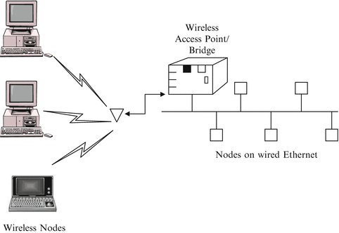
Connection of a wired LAN to wireless nodes
-
Act as a stand-alone WLAN for a group of wireless nodes. This can be achieved using topologies similar to wired LAN, namely, a star topology can be formed with central hub controlling the wireless nodes, a ring topology with each wireless node receiving or passing information sent to it or a bus topology with each wireless capable of hearing everything said by all the other nodes.

9.2.2 Technologies
When designing WLANs, manufacturers have to choose from two main technologies that are used for wireless communications today: radio frequency (RF) and infra red (IR). Each technologies has its own merits and demerits.
RF is used for applications where communications are over long distances and are not line-of-sight. In order to operate in the license free portion of the frequency spectrum known as the ISM band (Industrial, Scientific, and Medical), the RF system must use a modulation technique called spread spectrum (SS). (SS was used in IEEE 802.11b.) Spread spectrum is wideband radio frequency technology developed by the military during World War II for use in reliable, secure, mission-critical communications systems. SS system is one in which the transmitted signal is spread over frequency much wider than the minimum bandwidth required to send the signal. Using spread spectrum, a radio is supposed to distribute the signal across the entire spectrum. This way, no single user can dominate the band and collectively all users look like noise. The fact that such signals appear like noise in the band makes them difficult to find and jam, thereby increasing security against unauthorized listeners. There are two types of spread spectrum technology: frequency hopping and direct sequence.
Frequency hopping spread spectrum (FHSS) offers a current maximum data rate of 3 Mbps. It uses a narrowband carrier that changes frequency in a pattern known to both transmitter and receiver. It is based on the use of a signal at a given frequency that is constant for a small amount of time and then moves to a new frequency. The sequence of different channels for the hopping pattern is determined in pseudorandom fashion. This means that a very long sequence code is used before it is repeated, over 65,000 hops, making it appear random. Thus it is very difficult to predict the next frequency at which such a system will stop and transmit/receive data as the system appears to be a noise source to an unauthorized listener. This makes FHSS system very secure against interference and interception.
Direct sequence spread spectrum (DSSS) takes a signal at a given frequency and spreads it across a band of frequencies where the center frequency is the original signal. The spreading algorithm, which is the key to the relationship of the spread range of frequencies, changes with time in a pseudorandom sequence. When the ratio between the original signal bandwidth and the spread signal bandwidth is very large, the system offers great immunity to interference. For example, if 10 kbps signal is spread across 1 GHz of spectrum, the spreading ratio is 100,000 times or 50 dB. However, in the ISM band used in WLAN, the available bandwidth critically limits the ratio of spreading and so the advantages of DSSS scheme against interference is greatly limited. It has been shown that for the WLAN system using DSSS, the spreading ratio is at best ten times. DSSS is characterized by high cost, high power consumption, and more range than FHSS and infrared physical layers. FHSS is characterized by low cost, low power consumption, and less range than DSSS but greater range than infrared. Most WLAN systems use FHSS.
The second technology used in WLAN is Infra Red (IR), where the communication is carried by light in the invisible part of the spectrum. It is primarily used for very short distance communications (less than 1 m), where there is a line-of-sight connection. Since IR light does not penetrate solid materials (it is even attenuated greatly by window glass), it is not really useful in comparison to RF in WLAN system. However, IR is used in applications where the power is extremely limited such as a pager.
9.2.3 Standards
Although a number of proprietary, non-standard wireless LANs exist, standards have now been developed. Two international organizations have contributed to the development of standards for WLANs: the Institute of Electronics and Electrical Engineers (IEEE) and the European Telecommunications Standards Institute (ETSI). Mainly it is IEEE for 902.11; ETSI is involved in cellular.
In 1997, the IEEE 802.11 committee (http://ieee802.org/11) issued a standard for wireless LANs. The standard addresses the physical and MAC layers of the OSI model and includes the following [5, 6]:
-
A transmission rate of up to 2 Mbps
-
Two different media for transmission over wireless LAN: infrared (IR) and radio frequency (RF)
-
The media access control (MAC) protocol as carrier sense multiple access with collision avoidance (CSMA/CA), i.e. devices can interoperate with wired LANs via a bridge
-
MAC protocol provides two service types: asynchronous and synchronous (or contention-free). The asynchronous type of service is mandatory while the synchronous type is optional
-
MAC layer protocol is tied to the IEEE 802.2 logical link control (LLC) layer making it easier to integrate with other LANs
-
Three different physical layers: an optical-based physical-layer implementation that uses IR light to transmit, two RF based physical-layer choices: direct sequence spread spectrum (DSSS) and frequency hopping spread spectrum (FHSS) both operating at 2.4 GHz industrial, scientific, and medical (ISM) frequency bands. (The ISM bands 902–928 MHz, 2,400–2,483.5 MHz, and 5,725–5,850 MHz do not require a license to operate.) The IEEE 802.11 specifications for DSSS wireless LAN is shown in Fig. 9.3.
Fig. 9.3 
Eleven 22-MHz-wide channels for DSSS wireless LANs
-
Added features to the MAC that can maximize battery life in portable clients via power-management schemes.
-
Data security through which the wireless LANs can achieve wired equivalent privacy.

The standard basically defines the media and configuration issues, transmission procedures, throughput requirements, and range characteristics for WLAN technology. It avoids rigid requirements and gives room for vendors in the following areas: multiple physical media, common MAC layer irrespective of the physical layer, common frame format, power limit, and multiple on-air data rates [7].
There are three major problems encountered by an RF LAN [8]. First, frequency allocation is limited for LANs. But since LANs operate with low power, frequency reuse is possible. Second, interference from other wireless LANs controlled by different organization and other wireless sources is a problem. This problem can be controlled by using spread spectrum techniques. Third, security is at stake because RF signal can penetrate through the wall and hostile operators can intercept RF LAN communications. Encryption can be used to lessen this problem. IR LAN uses both laser diodes and light-emitting diodes as emitters. It is useful in high electromagnetic interference (EMI) environments. It is also secure since IR signal cannot penetrate the wall.
CSMA/CA is slightly different from carrier sense multiple access with collision detection (CSMA/CD), which is the MAC protocol used in Ethernet wired LAN. In CSMA/CA, when a node has something to transmit, it waits for silence on the network. When no other nodes are heard, it transmits and waits to receive an acknowledgement from the recipient node. If it fails to receive an acknowledgement within a time period, it assumes that collision has occurred and follows a process similar to CSMA/CD. Each node then waits for silence and only transmits after a random amount of waiting. While CSMA/CA protocol is slower that CSMA/CD due to the need for waiting for acknowledgement, it works well for wireless LANs. Also, WLANs operate in strong multipath fading channel where channel characteristics can change resulting in unreliable communication.
The ETSI devoted its attention to RF wireless LANs. The ETSI is close to finalizing its standard, which is based on the 2.4 GHz range used for spread-spectrum LANs in several European countries. European standard WLAN, called HiperLAN, will allow speeds of 24 Mbps [9].
Besides IEEE and ETSI, there are organizations that are more interested in the implementation and interoperability of WLAN products. Such organizations include Wireless LAN Alliance (WLANA at www.wlana.com) and Wireless Ethernet Compatibility Alliance (WECA at www.wi-fi.org or www.wirelessethernet.com). WLANA was formed in 1996 with 12 members as a trade association for wireless LAN vendors. WECA is a nonprofit manufacturing consortium with over 60 companies as members; it was formed in 1999 to certify interoperability of IEEE 802.11 products. Research groups are working hard to shrink radios into a chip that can be mass produced cheaply. If they succeed, the demand for radio LANs may follow the same trend as cellular phones in recent years.
9.2.4 Performance Analysis
We now present an accurate but simple analytical evaluation of the wireless networks using gated and exhaustive polling protocols combined with the stop-and-wait or go-back-N automatic repeat request (ARQ) techniques. In gated access policy, upon receiving a polling message, a station is permitted to transmit all packets stored in its buffer until that time. For the exhaustive policy, a station upon receiving a polling message is permitted to transmit all packets in its buffer as well as packets arriving while transmitting.
Assuming that the transmission system is completely symmetric, the average packet waiting time for gated policy is (in slots)
where λ is the arrival rate; N is the number of stations; t is the packet transmission time with first moment \( \overline{t} \) and second moment \( \overline{t^2} \); R is the walk time with first moment \( \overline{R} \) and second moment \( \overline{R^2} \). For exhaustive policy, the corresponding equation is
The above analysis has been presented in a summarized form. For more details, the interested reader is referred to [10, 11].
The above model is on a general WLAN. We now consider an IEEE 802.11 based WLAN, where the nodes use Distributed Coordination Function (DCF) mode of the MAC protocol. We recall that DCF is governed by a “listen-before-talk” protocol known as CSMA. Every station that wants to transmit first senses the channel for at least a duration of DIFS (Distributed Inter Frame Spacing). If the channel is idle for the entire DIFS, the station transmits the packet. Otherwise, it avoids collision by selecting a random back-off time uniformly distributed in the range [0, CW], where CW is the Contention Window. Under saturation conditions, the CSMA/CA process can be modeled as a two dimensional Markov chain.
We now can express the probability τ that a station transmits in a randomly selected slot time. Let p be the probability that its transmission will collide with at least one other node. In [12–14], the access probability τ is related to the collision probability of each packet p as
where W is the minimum backoff window in terms of backoff slots, and m is the maximum backoff stage. Notice from Eq. (9.9) that when m = 0, i.e. no exponential backoff is considered,
i.e. τ is independent of p. However, τ generally depends on the collision probability p, which is yet to be found. To find p. we note that p is the probability that, in a time slot, at least one the n − 1 remaining stations transmits
Equations (9.9) and (9.11) together form a system of nonlinear system and need to solved using numerical techniques (e.g. Newton’s method). Once τ is known, we can calculate the throughput.
Let S be the normalized system throughput, defined as the fraction of time the channel is used to successfully transmit. Let P tr be the probability that there is at least one transmission in the considered slot time. Since n stations contend for transmission and each transmit with probability τ:
The probability Ps that a transmission is successful is
We now express the throughput S as the ratio
If E[P] is the average packet payload size, the average amount of payload information successfully transmitted in a slot time is P tr P s E[P], since a successful transmission occurs in a slot time with probability P tr P s . Hence, Eq. (9.14) becomes
Where σ is the duration on an empty slot time, Ts is the average time the channel is senses busy because of a successful transmission, and Tc is the average time the channel is sensed busy by each node during a collision.
Other models on performance analysis of WLAN and WMAN can be found in [15–17].
9.3 Multiple Access Techniques
Since spectrum is a scarce and limited resource, multiple access schemes are designed to share the resource among a large number of wireless users. There are three popular multiple-access techniques for sharing the available bandwidth in a wireless communication system:
-
The frequency division multiple access (FDMA) serves users with different frequency channels. Signals are transmitted in nonoverlapping frequency bands that can be separated using bandpass filters.
-
The time division multiple access (TDMA) serves users with different time slots. Signals are transmitted in nonoverlapping time slots in a round-robin fashion. In each slot only one user is allowed to either transmit or receive.
-
The code division multiple access (CDMA) serves users with different code sequences. Different users employ signals that have small cross-correlation.
The three access methods are portrayed in Fig. 9.4. In addition to FDMA, TDMA, and CDMA, there are other two multiple access schemes—polarization division multiple access (PDMA) which serves users with different polarization and space division multiple access (SDMA) which controls the radiated energy for users in space by using spot beam antenna [18].

Multiple access techniques for wireless systems
9.3.1 FDMA, TDMA, and CDMA
FDMA requires that the total bandwidth be divided into a number of disjoint frequency subchannels. Each subchannel is assigned on demand to individual users who request service. As shown in Fig. 9.4, guard bands are maintained between adjacent spectra to minimize cross talk between channels. The present FM radio subdivides the spectrum into 30-kHz channels so that each channel is assigned to one user. In FDMA, the 30-kHz channel can be split into three 10-kHz channels. This band-splitting, however, incurs costs. For reasons of spectral efficiency, the transmission rate on a single FDMA channel is usually close to the maximum rate required by the user. Consequently, FDMA is suitable for users with nonbursty and predictable traffic. Cellular networks do not use FDMA by itself anymore. That passed with first generation networks. TDMA, at least in cellular, is used with FDMA. TDMA and CDMA can support more users in the space spectrum region. The GSM air interface uses a mixture of FDMA and TDMA.
TDMA is a channelization scheme that triples the capacity of the available channels without requiring additional RF spectrum. A frame consists of a number of time intervals called slots. As shown in Fig. 9.5, each TDMA frame consists of a preamble, information message, and trail bits. The preamble has the address and synchronization information that both the base station and the subscribers will use to identify each other. Guard times are used between slots to minimize cross talk. One downside of TDMA is that the high rate switching/multiplexing of the time-domain transmission signals places stringent requirements on the analog components following the modulator.

TDMA frame structure
CDMA is a spread spectrum technique in which the narrowband signal from each user is spread out in frequency using a unique spreading code. Several signals may occupy the same frequency band and still be individually recovered by the receiver with the knowledge of the spreading code. Each user operates independently of other users. Each user is assigned a unique code sequence that he uses to encode his information signal. The receiver, fully aware of the code sequence of the user, decodes the received signal after reception and recovers the original data.
9.3.2 Performance Analysis
In this section, we develop some analytical models to provide insights into the characteristics of FDMA and TDMA systems [19]. Suppose N users, each with infinite buffer size, transmit packets of constant length L bits. The packet arriving rate is λ packets/s. For TDMA, packets are transmitted using the full channel bandwidth of NR bps, while FDMA systems transmit at R bps.
9.3.2.1 Frequency Division Multiple Access
The queueing model is shown in Fig. 9.6.

Queueing model of FDMA
Using the result of M/G/1 queueing model, the waiting time is
The overall delay is
For the queue to be stable with finite delay,
9.3.2.2 Time Division Multiple Access
The delay in TDMA comprises of two components: (a) waiting time for the start of the time slot, (b) waiting time for packets that arrived earlier in the same queue to be transmitted. Using the result of M/G/1 queue,
The second term represents the fact that on the average, an arriving packet has to wait half the frame length (NL/R) before it is transmitted in its own time slot. The overall delay is
Note that
i.e.
This indicates that in terms of performance TDMA is superior to FDMA because the packet delay in FDMA is typically larger than TDMA. For three or more users, the overall delay in FDMA is greater than TDMA.
9.4 Cellular Communications
Perhaps no single development has done more for wireless technologies than has cellular communications. It is one of the fastest growing and most demanding telecommunication applications. It has been predicted that cellular will be the universal method of personal communication.
9.4.1 The Cellular Concept
The cellular concept is not so much a new technology as it is a new idea of organizing old technology. It was developed in 1947 at Bell Laboratories; the first cellular system began operation in Japan in 1979, and the first cellular system in the U.S. began in October, 1983 in Chicago. The first generation of cellular systems was based on analog FM radio technology. The second-generation cellular systems are based on digital radio technology and conform to at least three standards: GSM for Europe and international applications, AMPS for the U.S., and JDC for Japan. Third-generation cellular systems use TDMA, CDMA, CSMA, and FDMA.
The conventional approach to mobile radio involved setting up a high-power transmitter on top of the highest point in a coverage area. The mobile telephone had to have a line-of-sight to the base station for proper coverage. Line-of-sight transmission is limited to as much as 40–50 miles on the horizon. Also, if a mobile travels too far from the base station, the quality of the communications link becomes unacceptable. These and other limitations of conventional mobile telephone systems are overcome by cellular technology.
Areas of coverage are divided into small hexagonal radio coverage units known as cells. (The hexagonal shape is only for the sake of illustration; the shapes of real cells are irregular.) A cell is the basic geographical unit of a cellular system. A cellular communications system employs a large number of low-power wireless transmitter, as shown in Fig. 9.7.

A typical wireless seven-cell patterns; cells overlap to provide greater coverage
Cells are base stations transmitting over small geographical areas that are represented as hexagons. Cell size varies depending on the landscape and tele-density. Each side typically covers a maximum area of 15 miles across, depending on the local terrain. Urban cells are smaller for reuse. The cell sites are spaced over the area to provide a slightly overlapping blanket of coverage. Like the early mobile systems, the base station communicates with mobiles via a channel. The channel is made of two frequencies: the forward link for transmitting information to the base station and the reverse link to receive from the base station.
9.4.2 Fundamental Features
Besides the idea of cells, the essential principles of cellular systems include cell splitting, frequency reuse, hand-off, capacity, spectral efficiency, mobility, and roaming [1, 20].
-
Cell splitting: As a service area becomes full of users, the area is split into small ones. Consequently, urban regions with heavy traffic can be split into as many areas as necessary to provide acceptable service, while a large cell can be used to cover remote rural regions. Cell splitting increases the capacity of the system.
-
Frequency reuse: This is the core concept that defines the cellular system. The cellular-telephone industry is faced with a dilemma: services are growing rapidly and users are demanding more sophisticated call-handling features, but the amount of the electromagnetic spectrum allocation for cellular service is fixed. This dilemma is overcome by the ability to reuse the same frequency (channel) many times. Several frequency reuse patterns are in use. A typical example is shown in Fig. 9.8, where all available channels are divided into 21 frequency groups numbered 1–21. Each cell is assigned three frequency groups. For example, the same frequencies are reused in the cell designated as 1 and adjacent locations do not reuse the same frequencies. A cluster is a group of cells; frequency reused does not apply to clusters.
Fig. 9.8 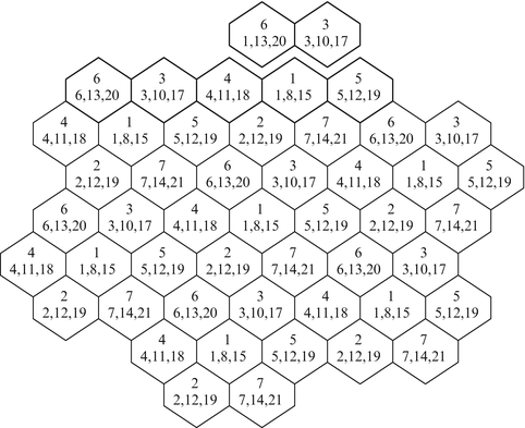
Frequency reuse in a seven-cell pattern cellular system
-
Hand-off: This is another fundamental feature of the cellular technology. When a call is in progress and the switch from one cell to another becomes necessary, a hand-off takes place. Hand-off is important, because adjacent cells do not use the same radio channels as a mobile user travels from one cell to another during a call, the call must be either dropped (blocked) or transferred from one channel to another. Dropping the call is not acceptable. Hand-off was created to solve the problem. Handing off from cell to cell is the process of transferring the mobile unit that has a call on a voice channel to another voice channel, all done without interfering with the call. The need for hand-off is determined by the quality of the signal, whether it is weak or strong. A hand-off threshold is predefined. When the received signal level is weak and reaches the threshold, the system provides a stronger channel from an adjacent cell. The hand-off process continues as the mobile moves from one cell to another as long as the mobile is in the coverage area. A number of algorithms are used to generate and process a hand-off request and eventual hand-off order.
-
Mobility and roaming: Mobility implies that a mobile user while in motion will be able to maintain the same call without service interruption. This is made possible by the built-in hand-off mechanism that assigns a new channel when the mobile moves to another cell. Because several cellular operators within the same region use different equipment, and a subscriber is registered with only one operator, some form of agreement is necessary to provide services to subscribers. Roaming is the process whereby a mobile moves out of its own territory and establishes a call from another territory.
-
Capacity: This is the number of subscribers that can use the cellular system. For a circuit-switched system, the capacity is determined by the loading (number of calls and the average time per call). Capacity expansion is required because cellular system must serve more subscribers. It takes place through frequency reuse, cell splitting, planning, and redesigning of the system.
-
Spectral efficiency: This is a performance measure of the efficient use of the frequency spectrum. It is the most desirable feature of a mobile communication system. It produces a measure of how efficiently space, frequency, and time are utilized. Expressed in channels/MHz/km2, channel efficiency is given by

where Bw is bandwidth of the system in MHz, Bc is the channel spacing in MHz, Nc is the number of cells in a cluster, N is the frequency reuse factor of the system, and Ac is the area covered by a cell in km2.
9.4.3 Performance Analysis
There are two common performance indices used in designing cellular systems [21, 22]. The first index is the call blocking probability, which is the probability that a new, originating call is denied due to the unavailability of free channels. The second index is the call dropping probability of hand-off call, which is the probability that an ongoing call is ended while a hand-off attempt is being made, again due to the unavailability of free channels. These two metrics are used with different traffic load to show the performance of a proposed system. A major goal is to keep these probabilities as low as possible by effectively utilizing the bandwidth.
To determine the two metrics, let λ i be the hand-off request rate for traffic type i ∈ {0,1, ⋯,n}, which follows a Poisson process and 1/μ i be the mean holding time of a channel for traffic type i within an exponential distribution. When j channels are busy, handoff calls depart at rate jμ i . When the number of requested channels reaches the total number of available channels si, i.e. j = si, then all channels are in use and the channel exchange rate is s i μ i . In this case, any new arriving hand-off call is blocked.
Let Pj be the probability that j channels exchanges are requested for traffic type i. Then P0 is the probability that no channel exchange is requested for traffic type i. The balance equations are [23]:
It then follows that
where \( {\rho}_i=\frac{\lambda_i}{\mu_i} \) is the offered load. Since the sum of the probabilities must be 1,
Thus, from Eqs. (9.27) and (9.28), we obtain
When j = s i , all the available channels are busy and any handoff call gets blocked. Thus, the handoff dropping probability is given by
It is evident from Eq. (9.30) that the dropping probability \( {P}_{s_i} \) is directly proportional to the mean channel exchange time. Also, the dropping probability decreases when the number of available channels increases. This means that the more bandwidth is available in a cell, the less chance a handoff call is blocked.
9.5 Summary
-
1.
The ALOHA systems are random time-division multiple access systems. They are used as a basis of comparing various random access methods. It is found that slotted ALOHA performs better than pure ALOHA
-
2.
Wireless LAN allows laptop PC and LAN users to link through radio waves or infrared links, eliminating the need for restrictive cables and opening a wider range of possible applications.
-
3.
The IEEE 802.16 standard addresses the “first-mile/last-mile” connection in wireless MANs. Such wireless MANs allow thousands of users share capacity for data, voice, and video.
-
4.
Multiple access techniques include TDMA, FDMA, and CDMA. In TDMA protocol, the transmission time is divided into frames and each user is assigned a fixed part of each frame, not overlapping with parts assigned to other users. In FDMA protocol, the channel bandwidth is divided into nonoverlapping frequency bands and each user is assigned a fixed band. CDMA protocols constitute a class of protocols in which multiple-access capability is primarily achieved by means of coding.
-
5.
Cellular systems operate on the principles of cell, frequency reuse, and hand-off.
References
M. N. O. Sadiku, Optical and Wireless Communications. Boca Raton: CRC Press, 2002.
N. Abramson, “Development of the ALOHANET,” IEEE Transactions on Information Theory, vol. 31, no. 2, March 1985, pp. 119-123.
A. Kumar et al., Wireless Networking. New York: Morgan Kaufman Publishers, 2008, pp. 194, 195.
G. Keiser, Local Area Networks. New York: McGraw-Hill, 2nd ed., 2002, pp.108-112.
P. T. Davis and C. R. McGuffin, Wireless Local Area Networks. New York: McGraw-Hill, 1995, pp. 41-117.
N. J. Muller, Mobile Telecommunications Factbook. New York: McGraw-Hill, 1998, pp. 219-270.
V. K. Garg, K. Smolik, and J. E. Wilkes, Applications of CDMA in Wireless/Personal Communications. Upper Saddle River, NJ: Prentice Hall, 1997, pp. 233-272.
F. J. Ricci, Personal Communications Systems Applications. Upper Saddle River, NJ: Prentice Hall, 1997, pp. 109-118.
G. Anastasi et al, “MAC Protocols for Wideband Wireless Local Access: Evolution Toward Wireless ATM,” IEEE Personal Communications, Oct. 1998, pp. 53-64.
S. Nannicini and T. Pecorella, “Performance evaluation of polling protocols for data transmission on wireless communication networks,” Proceedings of IEEE 1998 International Conference on Universal Personal Communications, 1998, vol. 2, pp. 1241-1245.
R. Fantacci and L. Zoppi, “Performance Evaluation of Polling Systems for Wireless Local Communication Networks,” IEEE Transactions on Vehicular Technology, vol. 49, no. 6, Nov. 2000, pp. 2148-2157.
B. P. Tsankov, R. A. Pachamanov, and D. A. Pachamanova, “Modified Brady voice traffic model for WLAN and WMAN,” Electronics Letters, vol. 43, no. 23, Nov. 2007.
Z. Changping et al., “Performance analysis of a wireless local area networks (WLAN) in a coal-mine tunnel environment,” Mining Science and Technology, vol. 20, 2010, pp. 0629-0634.
Z. Yang et al., “Performance analysis of rate-adaptive cooperative MAC based on wireless local area networks,” The Journal of China Universities of Posts and Telecommunications, vol. 16, no. 5, 2009, pp. 78-85.
T. S. Rappaport, Wireless Communications: Principles and Practice. Upper Saddle River, NJ: Prentice-Hall, 2001, pp. 324-327.
B. Bing, Broadband Wireless Access. Boston, MA: Kluwer Academic Publishers, 2000, pp. 65-68.
C. M. Akujuobi and M. N. O. Sadiku, Introduction to Broadband Communication Systems. Boca Raton, FL: CRC Press, 2008.
P. V. Krishna et al., “An efficient approach for distributed dynamic channel allocation with queues for real-time and non-real-time traffic in cellular networks,” The Journal of Systems and Software, vol. 28, 2009, pp. 1112-1124.
A. Hamad, E. Morsy, and S. Adel, “Performance analysis of a handoff scheme for two-tier cellular CDMA networks.” Egyptian Informatics Journal, vol. 12, 2011, pp. 139-149.
S. M. Musa and N. F. Mir, “An analytical approach for mobility load balancing in wireless networks,” Journal of Computation and Information Technology, vol. 19, no. 3, 2011, pp. 169-176.
Author information
Authors and Affiliations
Problems
Problems
-
9.1
Show that the maximum value of the throughput is 0.184 for pure ALOHA and 0.368 for slotted ALOHA.
-
9.2
A computer network uses a pure ALOHA access method. Let the channel bit rate be 100 kbps and packet length be 20 bytes. If each node generates 20 packets/min on the average, how many stations can the network support?
-
9.3
A random access network uses the ALOHA access scheme. It consists of two stations which are 800 m apart. Assume each station generates frames at an average rate of 600 packets/s and that the data rate is 2 Mbps. Let the packet length be 12 bytes and the propagation velocity be 2 × 10⁸ m/s. (a) Calculate the probability of collision for pure ALOHA protocol. (b) Repeat for slotted ALOHA.
-
9.4
Compare and contrast CSMA/CD and CSMA/CA.
-
9.5
Compare and contrast RF LAN and IR LAN.
-
9.6
Consider a system with ten stations and deterministic values of walking times with \( \overline{R}=0.4\mu \mathrm{s} \). Assume message lengths are exponentially distributed with mean message length of 1,000 bits and gated service. Plot the mean message delay as a function of the total traffic load \( \rho =\lambda \overline{t}=0.1,0.2,\dots 0.8 \). Take the bit rate to be 1 Mbps.
-
9.7
Repeat the previous problem for exhaustive service.
-
9.8
Describe the requirements for the PHY, MAC, and DLC layers of a wireless ATM network.
-
9.9
Describe FDMA and CDMA.
-
9.10
An FDMA system has the following parameters:
-
λ/station = 100 bps
-
R = 106 bps
-
N = 50
-
L = 1,000 bits
Plot the mean delay versus offered load ρ.
-
Rights and permissions
Copyright information
© 2013 Springer International Publishing Switzerland
About this chapter
Cite this chapter
Sadiku, M.N.O., Musa, S.M. (2013). Wireless Networks. In: Performance Analysis of Computer Networks. Springer, Cham. https://doi.org/10.1007/978-3-319-01646-7_9
Download citation
DOI: https://doi.org/10.1007/978-3-319-01646-7_9
Published:
Publisher Name: Springer, Cham
Print ISBN: 978-3-319-01645-0
Online ISBN: 978-3-319-01646-7
eBook Packages: Computer ScienceComputer Science (R0)