
Abstract
Supercapacitors bridge the gap between conventional electrolytic capacitors and batteries. These are capacitors with electrochemical charge storage . The basic equations used to describe the capacitors are same in the case of supercapacitors but their mechanism of energy storage is different. Various electrode-active materials such as activated carbon, mesoporous carbon, carbon nanotubes , graphene, etc., are invariably used in the supercapacitors with high performance. Both aqueous and organic electrolytes are used in supercapacitors but high voltage can only be delivered by the supercapacitors manufactured with organic electrolytes. However, the cycle life of aqueous electrolyte-based supercapacitors is high when compared with the organic ones. The present and future flexible and wearable technologies necessitate the development of flexible solid-state capacitors to supply them power. Supercapacitors are found applications in a variety of fields such as electronics industry, hybrid electric vehicles , and power supplies . The two major demerits of the present supercapacitors are low energy density and high cost. Hence, novel low-cost supercapacitors should be developed with high energy density to fulfill the needs of society. The present chapter discusses the Faradaic and non-Faradaic processes, types of supercapacitors, structure—i.e., electrode, electrolyte, electrolyte membrane, and current collector —key parameters for estimation of performance, electrochemical characterizations, etc.
Access provided by Autonomous University of Puebla. Download chapter PDF
2.1 Introduction
Increased energy consumption and the depletion of fossil fuel lead to the thinking of novel alternative strategies to resolve the problem. Increasing energy consumption due to the increased levels of electronic devices in the society is a major challenge in reality. As the energy resources are limited, it is indeed mandatory to think the use of sustainable, renewable, and clean energy resources. The eco-friendly nature of renewable resources is highly welcomed for their implementation in energy production. Various renewable technologies such as solar, wind, and tidal are environmentally friendly, whereas the uses of fossil fuels are extremely harmful due to the production of CO2 and other effluents to the atmosphere. However, such energy conversion devices are facing problems of their intermittent nature of energy production. The energy can’t be produced at night when used solar technologies and cannot be produced at no wind when wind technologies are used. Hence, it is mandatory to couple these types of renewable energy conversion technologies with novel electrical energy storage systems. Electrical energy storage systems such as batteries and supercapacitors are promising energy storage devices in which they can fulfill the basic requirements of storing energy from the renewable energy conversion technologies. Supercapacitors are otherwise known as electrochemical capacitors. Hence, the electrical energy will be available round the clock as they can store energy for prolonged periods of time. Batteries and supercapacitors can function thus as uninterrupted power systems and hence have achieved much demand in the present scenario. Batteries are powerful in terms of their high energy densities , whereas the supercapacitors are beneficial in their high power densities. By coupling the renewable energy conversion technologies either with batteries or with supercapacitors, one can develop novel hybrid devices which can both produce and save energy simultaneously. Such hybrid energy technologies are very promising for the future electronic technologies to supply them power. In the case of heavy-duty applications, it is mandatory to have both energy density and power density simultaneously. Hence, novel hybrid devices have been developed by using batteries and supercapacitors. The performance of battery–supercapacitor modules is excellent, and they are suitable candidates in the field of hybrid energy vehicles. But the fundamental aspects of capacitor and different types of capacitor are discussed in Chap. 1. Figure 2.1 schematically represents the conceptual difference among the three energy storage systems, i.e., capacitor, supercapacitor, and conventional Li-battery. For better understanding, Table 2.1 represents a comparative of capacitor, supercapacitor, and conventional Li-battery.

2.2 History
The working principle of electrochemical capacitors is first explained by Becker and Ferry. They have systematically studied the working mechanism of an electrochemical capacitor, which they have assembled, and the same is patented later although the performance of the device is not awesome [6]. In 1960, research groups have been involved in the manufacturing of electrochemical capacitors and they tried to bring the same to market however, failed as the capacitors got technical failure. The popularity of conventional capacitors was also one of the potential reasons for their rejection as the dielectric capacitors were in the market more than hundred years at that time. After tremendous struggle and technical corrections, the first electrochemical capacitor came to exist in the market was the ‘MaxCap™,’ [7]. The different types of MaxCap™ electric double-layer capacitors are shown in Fig. 2.2.

MaxCap™ electric double-layer capacitors [8]
2.3 Faradaic and Non-Faradaic Processes
In electrochemical analysis, Faradaic and non-Faradaic processes represent two fundamental modes of electrode characteristic (Figs. 2.3 and 2.4). In Faradaic process, the charge transfer takes place during redox reaction at the electrode. However, a mere presence of redox reaction at the electrode side does not imply Faradaic process. For the conduction of the Faradaic process, electronic charge injected into an electrode during redox reaction should be transferred away from it and charge should not be stored at the electrode either. Generally, Faradaic process is observed in lead–acid batteries and fuel cells. In non-Faradaic process, no charge transfer takes place. Here, ionic and electronic charges remain at or in the electrode similar to adsorption and desorption processes. In non-Faradaic process, either there will be no redox reaction at all or there will be redox reaction with the reacting species staying at the electrode material . Non-Faradaic process is observed in electric double-layer capacitor (EDLC), intercalation, and electrode with redox active surface functionalities. In ideally polarized electrode, where no charge transfer takes place across metal solution and the interface, only Non-Faradaic process takes place. In charge transfer electrode, Faradaic and non-Faradaic both processes occur simultaneously [9].

Reprinted with permission from [9]
Difference between charge transfer versus charge storage using six examples.

Reprinted with permission from [9]
Key differences between Faradaic and non-Faradaic processes.
2.4 Types of Supercapacitors
Based on the mechanism of charge storage , supercapacitors are divided mainly into three categories (Fig. 2.5): (i) electric double-layer capacitors (EDLCs), (ii) redox capacitors , and (iii) hybrid capacitors . Supercapacitors are different from the conventional capacitors in terms of their energy storage . In the case of dielectric capacitors, the charge is stored electrostatically and in the case of supercapacitors; it is by chemical reactions between the electrodes of the capacitor and the electrolyte [10]. In the case of dielectric capacitors, no electrolyte is used, whereas in supercapacitors electrolytes are used between the two electrodes but both of them utilize the dielectric membrane.

Classification of supercapacitors based on the mechanism of charge storage
2.4.1 Electric Double-Layer Capacitor
In EDLC, the electrostatic force of attraction creates the electrolyte ions to adhere with the surfaces of the electrodes [11, 12]. During charging, electric charges are accumulated at the electrode/electrolyte interface and this leads to the formation of electric double-layer [13, 14]. Here, the charge storage is by the formation of electric double layer, and no charge transfer reactions such as Faradaic reactions take place. On voltage applications, one electronic layer of charges is formed on the surface lattice structure of the electrode material , and to compensate these charges further, ions of opposite polarity from the electrolyte material further accumulate on the surface of the electrode material [15]. These two layers of charges are separated by solvent molecules called inner Helmholtz plane. Because of the size difference of electrons and ions, charge density of the electronic layer on the electrode material is higher compared to that of ionic layer. To compensate this extra electronic charge density, diffused layer of ions comes into the picture. The electrode potential varies linearly till the outer Helmholtz layer and gradually becomes exponential as approaches to the diffuse layer. EDLC provides fast charge/discharge cycle because of electrostatic charge storage mechanism. Cycle life of EDLC is higher as compared to pseudocapacitor due to non-Faradaic charge storage mechanism . Since there are no chemical reactions, the composition of the electrode structure remains almost constant. Hence, high reversible capacity and long cycle life have been observed here [13, 16]. The schematic representation of an electric double-layer during charging and discharging conditions is shown in Fig. 2.6. During the charged condition, the electrolyte ions are adsorbed on the capacitor electrode surfaces, and during discharging, they go back to the electrolyte solution and the electrons are passed through the load connected at the external circuit. The number of ions adsorbed/desorbed on the capacitor electrode surface during charging depends on the surface area of the active material. Hence, the electrodes with large surface area much preferred since the maximum utilization of surface area leads to higher capacitance [13, 15]. In the past, activated carbons were used as electrode-active materials in electric double-layer capacitors, whereas the advanced capacitors utilize carbon nanomaterials with large surface area such as carbon nanotubes [17, 18], carbon nanopetals [19], and graphene [20].

Reprinted with permission from [22]
Principle of charge storage of electric double-layer capacitors, a process of charging, b after charging and c process of discharging.
Operating Principle of EDLC
Charge/discharge process of EDLC can be expressed by the following equations [21] On the positive electrode (2.1)

and on the negative electrode (2.2)

Net charging and discharging process (2.3)

where Ep and En are the positive and negative electrodes, respectively. I− and I+ represent the anion and cation of the electrolyte. e− stands for electron and // represents double-layer formation at the interface.
2.4.2 Pseudocapacitor
Pseudocapacitor stores energy by means of charge transfer reactions , i.e., by Faradaic reactions [23, 24]. A schematic representation of a pseudocapacitor is shown in Fig. 2.7. The reduction/oxidation happens at the capacitor electrodes, and these reactions should be reversible so that the cycle life of the supercapacitor will be high. In the case of electrodes in pseudocapacitors, they undergo continuous chemical changes during rapid charge/discharge cycling. Fast and reversible Faradaic redox reaction takes place in the pseudocapacitor. Adsorbed ions in pseudocapacitor do not undergo chemical transformation of the electrode material since charge transfer is the only process taking place [25]. Here, charge is transferred through the redox reaction , adsorption, and intercalation on the surface of the electrode material . Pseudocapacitance has been observed along with EDLC in the supercapacitor devices. Various electrode materials such as electronically conducting polymers, and transition metal oxides and also their nanocomposites are used for manufacturing supercapacitors [26,27,28]. These materials undergo reversible oxidation/reduction reactions for a long period of time, and hence, the energy density of such capacitors is generally very high and they exhibit high capacitance. Nanostructured materials with good porosity (preferably mesoporous structure) are highly preferred since these porous electrodes possess good diffusion of electrolyte ions through them. The performance of pseudocapacitors is excellent when compared with the electric double-layer capacitors but the power density of such capacitors remains generally low when compared with the latter one.

Reprinted with permission from [29]
Schematic representation of a redox capacitor .
There are three types of electrochemical processes, which contribute to charge transfer in pseudocapacitance as mentioned below
Adsorption pseudocapacitance: Adsorption pseudocapacitance is observed due to the adsorption and desorption of ions of the electrolyte on the electrode material . Adsorption process can be expressed by the following (2.4), where lead is adsorbed on the surface of gold electrode in 10 mM \({\text{HClO}}_{4} + 1\,{\text{mM PbF}}_{2}\)—[21, 30] (e.g., lead and gold system is shown here).
Redox pseudocapacitance: Redox pseudocapacitance predominates, when ions are electrochemically adsorbed on the surface of the electrode material with Faradaic charge transfer . For example, redox reaction of hydrated RuO2 in acid electrolyte (e.g., HClO4) can be expressed by the following (2.5) [21, 31]
Intercalation pseudocapacitance: In the intercalation pseudocapacitance, electrolyte ions intercalate into the Van der Waals gaps and lattice of the electrode material . For example, intercalation pseudocapacitance process can be expressed by the following (2.6) in which lithium ions of the electrolyte intercalate into the lattice of niobium oxide [21]
2.4.3 Hybrid Capacitor
The name hybrid capacitor implies that the supercapacitor consists of electrodes of two or more different electrode materials . The mechanism of energy storage by these electrodes will be a combination of both electric double-layer formations as well as by means of pseudo-Faradaic reactions [32, 33]. In hybrid capacitor , asymmetric electrode materials are used for electrical energy storage . Purpose behind the hybrid capacitor is to achieve high energy density . Hybrid capacitors have high potential window as well as high specific capacitance as compared to symmetric capacitor [21]. Three types of electrodes are used in general for hybrid capacitors , e.g., composite electrode, battery-type electrode, and asymmetric electrode. In composite electrode, carbon-based materials are incorporated with pseudocapacitive electrode material . In battery-type electrode, one of the electrodes will be of carbon and the other will be of battery electrode types. In asymmetric capacitor, both electrodes will be capacitive in nature; however, one will follow EDLC behavior and the other will be made of pseudocapacitive electrode material . Low self-discharge rate, high potential window , high energy density , and high specific capacitance are the key advantages of the hybrid electrochemical capacitors. A schematic representation of a hybrid capacitor is shown in Fig. 2.8. These types of supercapacitors have achieved great interest of the industries in the recent past due to their enormous charge storage capacity. Hybrid capacitors exhibit excellent characteristics when compared with the electric double-layer capacitors as well as redox capacitors . The new generation capacitors of these types are of huge potential. By combining Faradaic process with non-Faradaic processes, the hybrid capacitors are capable to store more charge, and hence, the energy density and the power density are very high. They exhibit high capacitances when compared with the electric double-layer as well as redox capacitors . Some hybrid capacitors are even capable to work in high voltages depending on the type of electrolyte used in their construction. These capacitors target the next-generation electronic devices to supply them power in a very efficient way. Hybrid capacitors have filled the gap between the electric double-layer capacitors and redox capacitors . For example, charge storage mechanism in hybrid capacitor is shown in the following (2.7) and (2.8), where highly porous graphite carbon (HPGC) is used as negative electrode and Ni2P2O7 used as positive electrode in aqueous NaOH electrolyte [34].

Reprinted with permission from [29]
Schematic representation of a hybrid supercapacitor.
At the positive electrode
At the negative electrode
2.5 Structure
The structure of a supercapacitor (Fig. 2.9) includes mainly four components: electrodes, electrolyte, current collectors , and electrolyte separator membrane [13].

Structure of a supercapacitor
Each component of a supercapacitor possesses a definite role in the operation. Supercapacitors are manufactured in various shapes and sizes. The various supercapacitor modules manufactured by the inventlab® company are shown in Fig. 2.10 (as representative for understanding). The details about each component of any standard supercapacitor are discussed in the next section.

Reprinted with permission from [35]
Supercapacitor modules manufactured by inventlab®.
2.5.1 Electrode
The active part of supercapacitor is the electrode, as the charge storage inside the supercapacitor depends on the type of the electrode-active materials used in them. Electrodes should have characteristics such as good electrical conductivity , large surface area , good porous structure , and good redox activity . The electrode-active material in electric double-layer capacitors does not undergo charge transfer reactions , whereas the redox capacitors possess such reactions. The electrodes in electric double-layer capacitors consist of a compact structure, whereas the redox capacitors are made up of electronically conducting polymers that are much flexible in nature. The selection of electrode-active materials is a pre-requisite for achieving the best performance. Recent progresses in the field of nanoscience and nanotechnology are helped to synthesize novel nanomaterials for supercapacitor application. The reason, why the nanostructured materials have been preferred, is because of their unique features when compared to macro- or microelectrode materials . Nanomaterials exhibit unique characteristics such as good electrical conductivity , large surface area to volume ratio, good thermal stability, and good chemical resistance. The porous structure of the electrode-active material can easily be modified by using nanostructured materials. As they exhibit large surface area , the electrolyte ions can easily be diffused through their pores and that will give rise to an enhancement in their performance. Hence, materials with comparatively larger surface area are preferred. Carbon nanomaterials include carbon nanotubes , graphene oxide, mesoporous carbons, carbon nanofibers , graphene, etc., which are widely used for the same purpose. Nanocomposite electrodes are also employed for manufacturing supercapacitor electrodes. The high performance of the nanocomposite electrodes has made them very attractive candidates in manufacturing supercapacitors with high capacitances and energy densities . One major issue rooted in the electrode materials is the cycle life as the electrode damage happens and deteriorates the performance after say 1000 cycles . Depending on the type of mechanism of charge storage by the electrode-active materials, they can be classified as (i) materials with double-layer capacitance, (ii) materials with pseudocapacitance, and (iii) nanocomposite materials with both double-layer capacitance and pseudocapacitance [13]. A brief overview can be obtained from Fig. 2.11.

Chart of various electrode-active materials used in supercapacitors [13]
The electrode materials of a supercapacitor device can be a number of types; they can be made of carbon nanomaterials, transition metal oxides, and electrically conducting polymers. In the next section, a brief overview on different materials used as electrode materials for fabrication of a supercapacitor has been discussed.
2.5.1.1 Carbon Nanomaterials
Nanostructured carbon materials have been attracted by the supercapacitor research due to their unique properties such as decent electronic conductivity , large surface area to volume ratio, good chemical and electrochemical stabilities , and environment-friendliness [36,37,38]. Carbon nanomaterials are widely used invariably in electric double-layer capacitors, redox capacitors , and in hybrid capacitors . The mechanism of electrical energy storage by carbon nanomaterials is by means of electrochemical double-layer formation. The carbon nanomaterials do not take part in the Faradaic reactions and that is the reason behind very high life of the carbon nanomaterial-based electric double-layer capacitors as compared to other types of supercapacitors. The pre-requisite for a carbon nanomaterial to be used in a supercapacitor is that it should exhibit a porous structure so that the electrolyte ions can easily be diffused through these pores, and the accessibility of the electrolyte ions toward the extreme inner pores will participate in the charge storage , and thereby, the performance of the supercapacitor will be enhanced. For storing huge amount of energy in a supercapacitor for a long period of time, the porous carbon nanomaterial-based electrodes should perform reversible oxidation/reduction reactions. That means, the adsorption of electrolyte ions at the electrode/electrolyte interface at the time of charging should be reversibly desorbed during the discharging step. If the ions are not desorbed completely or if they undergo some chemical reactions with the electrode, may lead to reduction in performance and subsequently the electrode architecture fails in such a way that the specific surface area available for the ion adsorption will be minimized. Not only porous architecture, the pore size and pore size distribution are also important in the case of carbon nanomaterial-based electrodes in supercapacitor application. As the pore sizes are within the mesopore range (i.e., in between 2 and 50 nm), the performance will be higher as the diffusion of electrolyte ions will be favorable for achieving higher capacitance [34, 39]. However, in the case of micropores (the size of the pores <2 nm) and macropores (the size of the pores >50 nm), the supercapacitor performance is found to be low. Good electronic conductivity of the carbon nanomaterials helps in the transport of electrons through them even after thousands of cycles as there will be no or negligible change in morphology. Examples of nanostructured carbon materials used as electrode-active materials in supercapacitors are carbon nanotubes (CNTs) , carbon nanofibers , carbon nanopetals, mesoporous carbons, graphene, etc. Both single-walled and multi-walled CNTs are used for the application. Detailed characteristics of activated carbon, graphene and reduced graphene oxide, carbon nanotubes , carbon nanofibers , polymers, electrodes, electrolytes, separators, and current collectors are discussed in Chaps. 4, 5, 6, 7, 8, 9, 10, 11 and 12, respectively.
2.5.1.2 Transition Metal Oxides
Transition metal oxides are much attracted by the attention of high capacitance supercapacitors due to their redox-type of charge storage . They are widely used in various energy conversion as well as energy storage applications due to the good mechanical, electronic, and redox properties [40,41,42]. Nanostructured and porous transition metal oxide-based electrodes are much preferred, as the electrolyte diffusion toward the interior pores will be high; thereby, an enhanced performance is obtained. The redox capacitance is coming as a result of their multiple valence state changes. Transition metal oxides can be classified into two categories: (i) noble transition metal oxides (e.g., RuO2, IrO2, etc.) [43, 44] and (ii) base transition metal oxides (e.g., MnO2, Co3O4, etc.) [45, 46]. The noble transition metal oxides are relatively costlier compared to the base transition metal oxides. The low-cost and environment-friendly nature of the base transition metal oxides have attracted much for the supercapacitor application; however, performance is relatively low when compared with the noble transition metal oxides. A major demerit of low energy densities of supercapacitors can be resolved by using novel transition metal oxides/hydroxides with novel design in the electrode architecture. Nanostructuring of the electrode architecture is the best strategy adopted for achieving the best performance of the supercapacitor. Detailed characteristics of transition metal oxides are discussed in Chap. 3.
2.5.1.3 Electronically Conducting Polymers
Electronically conducting polymers attracted the attention of flexible energy conversion and storage devices in the recent past. The good electronic conductivities and easy processability have made them successful candidates in those applications. Electronically conducting polymer-based electrodes for supercapacitor application have many advantages such as the redox-type charge storage acting as performance booster, feasibility of fabrication of flexible electrodes, and thereby opening up the provision of flexible supercapacitors . Flexible supercapacitors are mandatory for application in the flexible and wearable electronic devices , which have shown an increasing trend in the recent past. The charge storage by electronically conducting polymers is by a doping process. Examples of electronically conducting polymers used in supercapacitor electrode application are polypyrrole [47, 48], polyaniline [49, 50], poly(3,4-ethylenedioxythiophene) [51, 52], etc. The conductivity in case of polypyrrole is by means of p-doping. The pi-electrons will be removed from their conjugated structure, which leaves a net positive charge. Both the postulates related with ‘polarons’ as well as ‘bipolarons’ exist in the literature. For example, the schematic representation of the conduction mechanism of polypyrrole is shown in Fig. 2.12. Detailed characteristics of conducting polymers are given in Chap. 8.

Reprinted with permission from [53]
Schematic representation of the conduction mechanism in polypyrrole.
2.5.2 Electrolyte
The nature of electrolyte determines the power density of supercapacitors since the electrolyte resistance plays a major role in determining the same. The term ‘electrochemical series resistance’ is used to represent the collective resistances within the supercapacitor system. If the electrolyte resistance is high, the power density will be low. Different types of electrolytes are used in supercapacitors, namely aqueous, organic, ionic, etc. They are categorized into two types either liquid or solid. Different types of liquid and solid electrolytes are shown in Fig. 2.13. The selection of an electrolyte is based on the stable potential window in which it can work. Aqueous electrolytes (like acids, alkaline) offer low specific resistances and hence are suitable for manufacturing supercapacitors. Also, the price of aqueous electrolytes is very low when compared with the organic electrolytes , which is one of the major advantages. But the organic electrolytes offer high specific resistance, which in turn reduces the power density of the supercapacitor [13]. Aqueous electrolytes also have disadvantages such as instability at higher voltages, leading to electrode corrosion and are environmentally hazardous. But, on the other hand, the organic electrolytes are stable even at higher operating voltages and also very toxic and flammable. The reason, why the aqueous electrolytes experience small resistances, is because the protons are of high mobility and small size that lower the resistance. On the other hand, in the case of organic electrolytes, due to large sizes, the resistance has been increased. Hence, the selection of electrolyte as well as the porosity of the electrode architecture is important for best performance of the supercapacitor. As the supercapacitor operates for several thousands of cycles, the electrolyte depletion causes an increase in the internal resistance, which leads to a decrease in the capacitance and hence the energy density . This is the reason why both the aqueous and organic electrolytes are not much preferred in the commercially available supercapacitors. The selection of electrolytes in the commercial supercapacitors is ionic liquids . These special categories of electrolytes exhibit unique characteristics such as high conductivity and wide electrochemical potential window [54, 55]. Ionic liquids are non-flammable in nature, and this property makes them safe to handle. By adjusting the concentration of ionic liquids very high, electrolyte depletion can be minimized. They also possess good chemical and environmental stabilities, which have made them potential candidates for use in supercapacitors. A special category of electrolytes namely ‘gel polymer electrolytes’ has also attracted much popularity due to their enhanced electrochemical characteristics [56,57,58]. Gel polymer electrolytes can be used to fabricate supercapacitors with solid-state features. Solid-state supercapacitors manufactured by gel polymer electrolytes are highly advantageous for application in the next-generation flexible and wearable electronic technologies. Hence, a new type of electrolytes is put forward, namely ‘ionic liquid -based gel polymer electrolytes’ by combining features of both ionic liquids and gel polymer electrolytes [59, 60]. These have all the advantages of their individual counterparts and the demerits are waived off however, still the cost factor remains a major concern. Detailed characteristics of electrolytes are given in Chap. 10.

Different types of electrolytes for supercapacitor
2.5.3 Electrolyte Membrane
The functions of an electrolyte separator membrane are (i) to allow the passage of electrolyte ions and (ii) to avoid the short circuiting of the supercapacitor electrodes. The electrolyte membrane with good ionic conductivity is preferred for the supercapacitor application. A simple Xerox paper or a commercially available Whatman™ filter paper can serve the purpose. These types of electrolyte membranes are of low cost and hence affordable. Nanostructured electrolyte membranes are developed in the recent past as well [61,62,63]. One example is Nafion™ membrane. Nafion™ membranes exhibit high ionic conductivities due to their nanoscale properties and is widely used in commercial supercapacitors. However, the cost of Nafion™ is very high, and hence, it is mandatory to develop novel electrolyte membranes with low-cost polymers [64, 65]. The electrolyte membrane should have porous structure to transport the ions from electrolyte to electrodes, as shown in Fig. 2.14. Detailed characteristics of electrolyte membrane separator are given in Chap. 11.

Schematic representation of porous membrane to transport ions to electrodes
2.5.4 Current Collector
The function of current collector is to collect the electrons (hence current collector) from the electrode-active material and transport them to the external circuit. Metal plates are used for this purpose such as copper and aluminium. Sometimes, alloys are also used for the same; one example is steel plate. Generally, two current collectors are used on the surface of cathode and anode of supercapacitors, as shown in Fig. 2.15. Material characteristics of current collector for supercapacitor are discussed in Chap. 12.

Construction of supercapacitors using current collectors
2.6 Key Parameters for Estimation of Performance
The various parameters, which used to estimate the performance of the supercapacitor, are specific capacitance , energy density , and power density .
2.6.1 Specific Capacitance
Capacitance values for commercial capacitors are stated as ‘rated capacitance CR’ . This is the parameter for which the capacitor has been designed. Typical capacitance of supercapacitor is in Farad (F), three to six orders of magnitude higher than those of conventional capacitors. The capacitance can be calculated from cyclic voltammograms, galvanostatic charge/discharge curves, and from electrochemical impedance spectroscopy curves. Specific capacitance means capacitance with respect to a known entity such as mass, area, and volume. If the capacitance is calculated with respect to the mass of the electrode-active material used, it is known as gravimetric capacitance (i.e., capacitance per gram of the electrode-active material) and represented as F/g. If it is calculated with respect to the area of supercapacitor electrode, it is termed as area-specific capacitance and the unit F/cm2 is used to represent the same. If the capacitance is calculated with respect to the volume of the supercapacitor itself, it is known as volume-specific capacitance and is denoted by F/cm3. While calculating the specific capacitance, there usually exists a confusion that whether the specified capacitance is of the electrode or of the supercapacitor itself (which means that of two electrodes, not of the single electrode). Hence, it is better to use the term ‘specific capacitance’ such that the confusion can be avoided.
2.6.2 Energy Density
Energy density refers to the energy stored in a supercapacitor with respect to either mass of the electrode-active material or volume of the supercapacitor itself. If the energy density is calculated with respect to the mass of the electrode-active material used in the two electrodes of a supercapacitor, it is termed as gravimetric energy density and represented generally by W h kg−1 (Watt hour kg−1). If it is calculated with respect to the volume of the supercapacitor, it is known as volume-specific energy density and is represented by W h cm−3. But in all cases, the calculation of energy density remains the same as
where C is the specific capacitance (either in F g−1 or in F cm−3) and V is the operating voltage of the supercapacitor. From (2.9), it is clear that the energy density has a square dependency to the operating voltage; hence, higher energy density can be expected if the high voltage supercapacitor is used and that in turn depends on the type of electrolyte used in the construction of the supercapacitor. As discussed earlier, the maximum operable voltage is limited in the case of aqueous electrolytes, whereas it is high in the case of organic electrolytes . The energy density of supercapacitors is low when compared with batteries but several orders of magnitude greater than that of a conventional capacitor.
2.6.3 Power Density
Power density refers to the energy available from the supercapacitor in a unit time. Similar to the energy density , the power density too can be expressed in terms either of mass of the electrode-active material or volume of the supercapacitor itself. If the power density is calculated with respect to the mass of the electrode-active material used in the two electrodes of a supercapacitor, it is termed as gravimetric power density and it is represented generally by W kg−1 (Watt kg−1). If it is calculated with respect to the volume of the supercapacitor, it is known as volume-specific power density and is represented by W cm−3. But in all cases, the calculation of power density remains the same as
where Rs is the equivalent series resistance of the supercapacitor and V is the operable voltage. The equivalent series resistance of a supercapacitor depends on the electrolyte, where aqueous electrolytes offer comparatively less resistance with respect to the organic electrolytes . Hence, the power density will be high if aqueous electrolytes are used in the supercapacitor. Since organic electrolytes offer high resistances, the power density of the supercapacitor will be low. Hence, it can be said that the selection of electrolyte is crucial for determining the power density of the supercapacitor. The power density of supercapacitors is several orders higher than that of batteries. But achieving both high energy and power densities is a major challenge in the case of supercapacitors. Hence, the selection of proper electrode-active materials as well as hierarchical design of the supercapacitor is mandatory for developing high-performance supercapacitors. Energy and power densities of supercapacitors bridge the gap between the batteries and conventional capacitors, as shown in Fig. 2.16.

Reprinted with permission from [66]
Plots of energy density versus power density of batteries, supercapacitors, and conventional capacitors.
2.7 Electrochemical Characterizations
The electrochemical performance of supercapacitor electrodes and supercapacitors is examined by various electrochemical techniques such as electrochemical impedance spectroscopy, cyclic voltammetry, and galvanostatic charge/discharge measurements. A brief description on these techniques is given as follows.
2.7.1 Electrochemical Impedance Spectroscopy
Electrochemical impedance is a widely accepted tool used to compute impedance of a charge storage device as a function of frequency on application of alternative voltage superimposed of low amplitude on a steady-state potential [67, 68]. The data are represented graphically in a Bode plot to understand the supercapacitive response between the phase angle and frequency. The other popular method of evaluation of an impedance plot is Nyquist plot, where the imaginary and real parts of the impedances are displayed on a complex plane [69]. From the Nyquist plots, the intersection of the curves at the x-axis represents the bulk electrolyte resistance (Rb) of the supercapacitor electrodes. By using this value, the conductivity (σ) of the supercapacitor electrodes is determined as follows
where T is the total thickness of the supercapacitor (in cm), Rb is the bulk electrolyte resistance (in Ω), and Aele is the geometrical area of supercapacitor electrodes (in cm2). The first intercept point of the semi-circle on the real axis of the Nyquist plot is considered as Rb [70,71,72].
Again, the electrochemical impedance Z(w) is defined as
where ZI and ZII are the real and imaginary parts of the impedance, respectively.
The frequency-dependent behavior of a supercapacitor can be described by associating a serial resistance Rs and a capacitance C, as shown in Fig. 2.17. The impedance of the circuit is defined by

Schematic used for describing the frequency-dependent behavior of supercapacitor
It is possible to describe the supercapacitor by using resistance and capacitance (Fig. 2.18) that are functions of the pulsation w and denoted as R(w) and C(w). The impedance of the equivalent circuit is given by Taberna et al. [67]

Equivalent circuit of the supercapacitor
where K is the capacitance of the supercapacitor. By solving (2.14), it leads to
Equation 2.16 consists of a real part and an imaginary part for the capacitance of the supercapacitor. This (2.16) can be written as
where
Equation 2.18 gives the expression for the capacitance of the supercapacitor, which is varying with frequency, and (2.19) gives the imaginary part of the capacitance.
2.7.2 Cyclic Voltammetry
Cyclic voltammetry measurement applies a linearly changed electric potential between positive and negative electrodes of a supercapacitor in two-electrode cell configuration [73, 74]. The speed of the potential change in mV s−1 is referred as the scan rate, and the range of potential change is known as potential window . The instantaneous current during the anodic and cathodic sweeps is recorded, which is used to characterize the electrochemical reactions involved between the electro-active material and the electrolyte ions . Apart from the two-electrode cell arrangement, a three-electrode cell arrangement was also used for examining the electrode characteristics of the SC electrodes. The three electrodes used are the working, counter, and reference electrodes. A counter electrode of platinum and a reference electrode of saturated Ag/AgCl are generally used. In both the cases, the cyclic voltammetry data is plotted as current, I (in A), versus potential, E (in V). The performance parameters of supercapacitor can be calculated from the cyclic voltammetry curves. The overall capacitance value is calculated from the cyclic voltammogram by using (2.20) [75]
where ‘i’ is the instantaneous current in cyclic voltammograms, dE/dt represents the scanning rate, and ‘s’ is the potential sweep rate. The capacitance of the supercapacitor is the average current divided by the scanning rate (2.21) as
where E1 and E2 are the switching potentials in cyclic voltammetry, \(\it \int\nolimits_{{E_{1} }}^{{E_{2} }} {i\left( E \right)}\)dE is the voltammetric charge got by integration of positive or negative sweep in cyclic voltammograms. The upper limit potential is given by (2.22).
where t is the time period of single positive or negative sweep. Therefore,
and hence (2.21) becomes
The gravimetric capacitance can be calculated from (2.23) by dividing the capacitance with the mass of electrode-active material as
where m is the total mass of electrode-active material or materials used in the two supercapacitor electrodes.
2.7.3 Galvanostatic Charge/Discharge
Constant current charge/discharge is a versatile and accurate method used to characterize the supercapacitor under direct current. The constant current charge/discharge measurement is conducted by repetitive charging and discharging of the supercapacitor or working electrode at a fixed current level with or without a dwelling period (defined as a time period between charging and discharging while the peak voltage Vo is constant) and normally a plot of E (in V) versus time, t (in s) is the output [69, 76].
2.7.3.1 Calculation of Supercapacitor Parameters
The various supercapacitor performance parameters such as specific capacitance , energy density , and power density can be calculated from the galvanostatic charge/discharge curves, and the equations used for calculating the same are discussed in the next section.
Cell capacitance: The cell capacitance (Ccell) of the supercapacitor is calculated by (2.25),
where I is the charging current, tdis is the discharging time, and ΔE is the operating potential window .
Areal capacitance: The areal capacitance (Ccell,A) of the supercapacitor is calculated by (2.26),
where Acell is the total geometric area of two supercapacitor electrodes (i.e., two times the area of single electrode).
Areal energy density: The areal energy density (Ecell,A) of the supercapacitor is calculated by (2.27),
Area-specific capacitance: The area-specific capacitance (Ccell,sp,A) of the supercapacitor is calculated by (2.28),
where Aele is the geometric area of the supercapacitor electrodes.
Area-specific energy density: The area-specific energy density (Ecell,sp,A) of the supercapacitor is calculated by (2.29),
Volumetric capacitance: The volumetric capacitance (Ccell,V) of the supercapacitor is calculated by the (2.30),
where Vcell is the total volume of the supercapacitor.
Volumetric energy density: The volumetric energy density (Ecell,V) of the supercapacitor is calculated by (2.31),
Volumetric power density: The volumetric power density (Pcell,V) of the supercapacitor is calculated by (2.32)
Volume-specific capacitance: The volume-specific capacitance (Ccell,sp,V) of the supercapacitor is calculated by (2.33),
where Vele is the total volume of the supercapacitor electrodes.
Volume-specific energy density: The volume-specific energy density (Ecell,sp,V) of the supercapacitor is calculated by (2.34),
Volume-specific power density: The volume-specific power density (Pcell,sp,V) of the supercapacitor is calculated by (2.35),
Gravimetric capacitance: The gravimetric capacitance (Cm) of the supercapacitor is calculated by (2.36),
where ‘m’ is the total mass of electrode-active materials used in the supercapacitor (excluding the mass of current collector , separator and electrolyte).
Gravimetric energy density: The gravimetric energy density (Em) of the supercapacitor is calculated by (2.37),
Gravimetric power density: The gravimetric power density (Pm) of the supercapacitor is calculated by (2.38),
2.7.3.2 Estimation of Rate Capability of Supercapacitor
The rate capability of the supercapacitor is evaluated by performing the galvanostatic charge/discharge measurement at different current densities. Further, the supercapacitive performance parameters are calculated from the galvanostatic charge/discharge curves. The results obtained at different current densities are compared, and the rate characteristics of the concerned supercapacitor are estimated. Figure 2.19 shows an example of a rate capability plot of a graphene-transition metal-based supercapacitor [77].

Redrawn and reprinted with permission from [77]
Specific capacitance values of graphene-transition metal-based supercapacitor at different current densities and corresponding rate capability.
2.7.3.3 Testing of Flexibility of Supercapacitor
The flexibility of supercapacitor is examined by carrying out the galvanostatic charge/discharge measurement at different supercapacitor bending angles [78]. Further, the galvanostatic charge/discharge measurement is carried out at different bending angles and the E − t response is noted. Finally, the galvanostatic charge/discharge (GCD) curves obtained at different supercapacitor bending are compared. For an example, the GCD curves of a flexible supercapacitor based on graphene oxide and polyaniline at different bending angles [79] are shown in Fig. 2.20a. The stability of the capacitance at different bending cycles is also shown in Fig. 2.20b.

Redrawn and reprinted with permission from [79]
a GCD curves of a graphene oxide and polyaniline-based flexible supercapacitors at different bending angles, b capacitance retention of the supercapacitor at different bending cycles.
2.7.3.4 Estimation of Cycle Life of Supercapacitor
The life cycle of supercapacitor was determined by the cyclic voltammetry and galvanostatic charge/discharge measurements. In a typical procedure, the charging/discharging or cyclic voltammetry measurement of the SC at a particular current density or scan rate is carried out for ‘n’ number of cycles . Further, the supercapacitive performance parameters are estimated from the galvanostatic charge/discharge or cyclic voltammetry curves at particular cycle numbers and the results are compared [77, 80] as shown in Fig. 2.21.

2.7.3.5 Two-, Three-, and Four-Electrode Systems
Electrochemical test is used to study the redox reactions . In electrochemical process, electricity is generated by the movement of the electrons from one electrode material to other. These reactions are well known as oxidation-reduction (redox) reactions. Depending on the application, electrochemical testing can be done either in potentiostatic or in galvanostatic mode or both [81, 82].
The electrodes that are involved during electrochemical testing are discussed as follows:
-
(a)
Working electrode
Working electrode is one, which is to be studied, i.e., in this electrode, reaction of interest occurs. Some of the working electrodes such as glassy carbon, metal foam , and carbon cloth, are used to provide conductive pathway for the sample to be tested. For corrosion applications, the material to be investigated is itself used as a working electrode [81, 82].
-
(b)
Counter electrode
Counter electrode is also known as auxiliary electrode. During electrochemical testing, it is used to close the current circuit [83]. Mainly, inert materials such as platinum, graphite, gold, and glassy carbon are used as the counter electrode. Counter electrode does not participate in electrochemical reactions and acts as current source or sink [81, 82].
-
(c)
Reference electrode
Reference electrode is known as the electrode potential, which is used as a reference point for the electrochemical cells. This electrode has high stability and holds constant potential during the entire process of testing. Ideally, current does not flow from the reference electrode, which is again assured by using counter electrode. Some commonly used reference electrodes are mercury/mercury (mercurous) oxide, silver/silver chloride, saturated calomel, mercury/mercury sulfate, copper/copper sulfate, etc. which are displayed along with their reference voltage in Fig. 2.22 [81,82,83].
Fig. 2.22 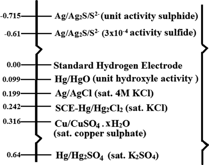
Redrawn and reprinted with permission from [81]
Potential scale of commonly used reference electrodes.

Along with working, counter, and reference electrodes, an electrochemical station has fourth connector as sense and fifth connector as a ground connector, which can be used to connect external devices to the same ground of electrochemical station [81, 82].
There are two modes in which electrochemical observations are carried out-
-
(a)
Potentiostatic mode: In potentiostatic mode, the potential of working electrode and reference electrode is well defined due to which the potential of counter against reference electrode is controlled [81].
-
(b)
Galvanostatic mode: In galvanostatic mode, the flow of current between counter electrode and working electrode and potential difference between reference electrode and working electrode are monitored. The current between working and counter electrode is controlled [81].
The three commonly used electrochemical cell setups, i.e., two-electrode, three-electrode, and four-electrode, are discussed here:
-
(a)
Two -electrode setup
In two-electrode setup, working electrode and sense are sorted to form one connector. For the other connector, counter and reference electrodes are sorted. Figure 2.23a shows the schematic diagram of two-electrode setup [81, 82]. This type of electrode setup is used to measure the electrochemistry of the entire cell. It measures the contributions from electrode to electrolyte interface. It offers ultra-fast dynamics of electrode electrochemistry and electrochemical impedance measurements at high frequencies [83].
Fig. 2.23 In two-electrode system, it is difficult to keep steady counter electrode potential (ec) during passage of current. The voltage drop (iRs) is not compensated across the solution leading to poor control of working electrode potential (ew) in two-electrode system [83]. The schematic representation of potential gradients across two electrodes is presented in Fig. 2.23b [81, 82]. This setup is commonly used to measure the cell voltage of electrochemical energy storage and conversion devices such as supercapacitor, batteries, photovoltaic panels, and fuel cells. For supercapacitor application, two-electrode setup is used to measure the performance of the whole assembly of electrodes, electrolyte, and separator in device form [83].
-
(b)
Three-electrode setup
Three-electrode setup is widely used electrochemical setup to study the electrochemistry of the electrode material . It consists of working, counter, and reference electrodes. Reference electrode acts as a potential reference for measuring and controlling the potential of the working electrode [81, 82]. Figure 2.24a shows the schematic representation of three-electrode setup. The current flows between counter and working electrode, whereas reference electrode and sense measure potential between them [82]. Figure 2.24b shows the schematic representation of potential gradient in three-electrode system when current is flowing. Also, reference electrode passes negligible current so, iR drop (iRu) between working and reference electrode is very small [83]. Counter electrode passes the current, which is required to balance the current obtained from the working electrode. Three-electrode setup shows superior control over working electrode potential. For energy storage and conversion devices, it offers preliminary studies to understand the behavior of electrode material with the electrolyte [81,82,83,84].
-
(c)
Four-electrode setup
In four-electrode setup, the potential between reference electrode and sense is measured during the flow of current between working and counter electrode. This setup is generally used to measure the junction potentials across the membrane or between two non-miscible phases. This allows to analyze the accurate measurement of the resistance of the membrane or liquid interface. Figure 2.25 shows the schematic representation of four-electrode setup [81, 82].
Fig. 2.25 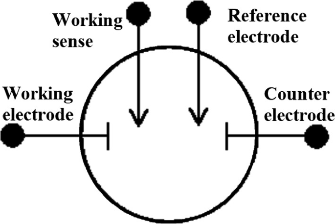
Redrawn and reprinted with permission from [82]
Simple schematic of four-electrode configuration.
Four–electrode system is also used in zero resistance ammeter experiment, where working and counter electrodes are sorted to maintain zero voltage drop. Here, reference electrode acts as a spectator electrode to working-counter coupling. This experiment is used to study electrochemical noise and galvanic corrosion [81, 82].


2.8 Concluding Remarks
In this chapter, a complete description of supercapacitors including the mechanism of charge, types, advantages, and demerits is included. Supercapacitors are classified into three classes, namely electric double-layer capacitors, redox capacitors , and hybrid capacitors . Electric double-layer capacitors possess non-Faradaic energy storage , and hence, no electrode damage happens for a large number of cycles. But in the case of redox capacitors , as they experience pseudo-Faradaic reactions , there chemical change happens to the electrode-active materials, and hence, they may lose their performance after few thousands of cycles . In order to avoid this, hybrid capacitors have been developed so that the disadvantages of electric double-layer capacitors and redox capacitors have been waived off and all the merits are added up in these advanced capacitors. Supercapacitors exhibit high power densities when compared with batteries, whereas their energy density is lower than that of the batteries. The future supercapacitors should be equipped with high energy density to fulfill the requirements. The main challenge of supercapacitor industry is the cost of production, which is making them ‘not-reachable’ to the society.
References
R.B. Marichi, V. Sahu, R.K. Sharma, G. Singh, Handbook of Ecomaterials, pp 1–26
X. Zhang, L. Ji, O. Toprakci, Y. Liang, M. Alcoutlabi, Polym. Rev. 51, 239 (2011)
M. Lu, F. Beguin, E. Frackowiak, in Supercapacitors: Materials, Systems, and Applications
M. Winter, R.J. Brodd, Chem. Rev. 104, 4245 (2004)
R.R. Gaddam, N.A. Kumar, R. Narayan, K.V.S.N. Raju, X.S. Zhao, in Nanomaterials Synthesis Design, Fabrication and Applications (2019), pp 385–418
H.I. Becker, (Google Patents, 1957)
D.L. Boos, (Google Patents, 1970)
https://www.kanthal.com/en/. Accessed 10 Feb 2019
P.M. Biesheuvel, J.E. Dykstra, The difference between Faradaic and Nonfaradaic processes in Electrochemistry
A. Pandolfo, A. Hollenkamp, J. Power Sour. 157, 11 (2006)
B.E. Conway, J. Electrochem. Soc. 138, 1539 (1991)
B.E. Conway, Electrochemical Supercapacitors: Scientific Fundamentals and Technological Applications (Springer Science & Business Media, 2013)
K.K. Kar, S. Rana, J. Pandey, Handbook of Polymer Nanocomposites Processing, Performance and Application (Springer, 2015)
A. Burke, J. Power Sour. 91, 37 (2000)
Y. Zhang, H. Feng, X. Wu, L. Wang, A. Zhang, T. Xia, H. Dong, X. Li, L. Zhang, Int. J. Hydrogen Energy 34, 4889 (2009)
C. Du, N. Pan, Nanotechnology 17, 5314 (2006)
J. Cherusseri, K.K. Kar, RSC Adv. 5, 34335 (2015)
J. Cherusseri, R. Sharma, K.K. Kar, Carbon 105, 113 (2016)
J. Cherusseri, K.K. Kar, J. Mater. Chem. A 3, 21586 (2015)
Y.B. Tan, J.-M. Lee, J. Mater. Chem. A 1, 14814 (2013)
C. Zhong, Y. Deng, W. Hu, D. Sun, X. Han, J. Qiao, J. Zhang, in Electrolytes for Electrochemical Supercapacitors (CRC Press, 2016), p. 347
Y. Lin, H. Zhao, F. Yu, J. Yang, Sustainability 10, 3630 (2018)
G. Ma, M. Dong, K. Sun, E. Feng, H. Peng, Z. Lei, J. Mater. Chem. A 3, 4035 (2015)
S. Senthilkumar, R.K. Selvan, J. Melo, J. Mater. Chem. A 1, 12386 (2013)
B.E. Conway, in Electrochemical Supercapacitors Scientific Fundamentals and Technological Applications (1999), p. 698
J. Cherusseri, K.K. Kar, J. Mater. Chem. A 4, 9910 (2016)
J. Cherusseri, K.K. Kar, PCCP 18, 8587 (2016)
J. Cherusseri, K.K. Kar, RSC Adv. 6, 60454 (2016)
E. Lim, C. Jo, J. Lee, Nanoscale 8, 7827 (2016)
E. Herrero, L.J. Buller, H.D. Abruña, Chem. Rev. 101, 1897 (2001)
S. Trasatti, G. Buzzanca, J. Electroanal. Chem. Interfacial Electrochem. 29, A1 (1971)
B. Senthilkumar, Z. Khan, S. Park, K. Kim, H. Ko, Y. Kim, J. Mater. Chem. A 3, 21553 (2015)
N. Xu, X. Sun, X. Zhang, K. Wang, Y. Ma, RSC Adv. 5, 94361 (2015)
Z. Zhao, S. Hao, P. Hao, Y. Sang, A. Manivannan, N. Wu, H. Liu, J. Mater. Chem. A 3, 15049 (2015)
www.inventlab.ch. Accessed 10 Feb 2019
S. Bose, T. Kuila, A.K. Mishra, R. Rajasekar, N.H. Kim, J.H. Lee, J. Mater. Chem. 22, 767 (2012)
K.K. Kar, Composite Materials: Processing, Applications, Characterizations (Springer, 2016)
Z. Lu, Y. Chao, Y. Ge, J. Foroughi, Y. Zhao, C. Wang, H. Long, G.G. Wallace, Nanoscale 9, 5063 (2017)
L. Jiang, L. Sheng, X. Chen, T. Wei, Z. Fan, J. Mater. Chem. A 4, 11388 (2016)
S.R. Ede, S. Anantharaj, K. Kumaran, S. Mishra, S. Kundu, RSC Adv. 7, 5898 (2017)
P.H. Jampani, O. Velikokhatnyi, K. Kadakia, D.H. Hong, S.S. Damle, J.A. Poston, A. Manivannan, P.N. Kumta, J. Mater. Chem. A 3, 8413 (2015)
L. Li, R. Li, S. Gai, F. He, P. Yang, J. Mater. Chem. A 2, 8758 (2014)
D.-Q. Liu, S.-H. Yu, S.-W. Son, S.-K. Joo, ECS Trans. 16, 103 (2008)
R. Liu, J. Duay, T. Lane, S.B. Lee, PCCP 12, 4309 (2010)
M. Huang, F. Li, F. Dong, Y.X. Zhang, L.L. Zhang, J. Mater. Chem. A 3, 21380 (2015)
M. Qorbani, T.-C. Chou, Y.-H. Lee, S. Samireddi, N. Naseri, A. Ganguly, A. Esfandiar, C.-H. Wang, L.-C. Chen, K.-H. Chen, J. Mater. Chem. A 5, 12569 (2017)
L.M. Santino, S. Acharya, J.M. D’Arcy, J. Mater. Chem. A 5, 11772 (2017)
L. Yuan, B. Yao, B. Hu, K. Huo, W. Chen, J. Zhou, Energy Environ. Sci. 6, 470 (2013)
C.O. Baker, X. Huang, W. Nelson, R.B. Kaner, Chem. Soc. Rev. 46, 1510 (2017)
M. Umashankar, S. Palaniappan, RSC Adv. 5, 70675 (2015)
M. Rajesh, C.J. Raj, B.C. Kim, R. Manikandan, S.-J. Kim, S.Y. Park, K. Lee, K.H. Yu, RSC Adv. 6, 110433 (2016)
Z. Su, C. Yang, C. Xu, H. Wu, Z. Zhang, T. Liu, C. Zhang, Q. Yang, B. Li, F. Kang, J. Mater. Chem. A 1, 12432 (2013)
R. Ramya, R. Sivasubramanian, M. Sangaranarayanan, Electrochim. Acta 101, 109 (2013)
M. Deschamps, E. Gilbert, P. Azais, E. Raymundo-Piñero, M.R. Ammar, P. Simon, D. Massiot, F. Béguin, Nat. Mater. 12, 351 (2013)
C. Zhong, Y. Deng, W. Hu, J. Qiao, L. Zhang, J. Zhang, Chem. Soc. Rev. 44, 7484 (2015)
S. Hashmi, R. Latham, R. Linford, W. Schlindwein, Polym. Int. 47, 28 (1998)
X. Yang, F. Zhang, L. Zhang, T. Zhang, Y. Huang, Y. Chen, Adv. Funct. Mater. 23, 3353 (2013)
H. Yu, J. Wu, L. Fan, Y. Lin, K. Xu, Z. Tang, C. Cheng, S. Tang, J. Lin, M. Huang, J. Power Sour. 198, 402 (2012)
M. Armand, F. Endres, D.R. MacFarlane, H. Ohno, B. Scrosati, in Materials for Sustainable Energy: A Collection of Peer-Reviewed Research and Review Articles from Nature Publishing Group (World Scientific, 2011), p. 129
Y.J. Kang, H. Chung, C.-H. Han, W. Kim, Nanotechnology 23, 065401 (2012)
H. Dai, H. Zhang, H. Zhong, H. Jin, X. Li, S. Xiao, Z. Mai, Fuel Cells 10, 754 (2010)
Z. Mahmud, N. Zaki, R. Subban, A. Ali, M. Yahya, in 2012 IEEE Colloquium on Humanities, Science and Engineering (CHUSER) (IEEE, 2012), p. 621
M. Rosi, M. P. Ekaputra, M. Abdullah, Khairurrijal, in AIP Conference Proceedings (AIP, 2010), p. 55
S. Banerjee, K.K. Kar, Recent Pat. Mater. Sci. 7, 131 (2014)
S. Banerjee, K.K. Kar, M.K. Das, Recent Pat. Mater. Sci. 7, 173 (2014)
I. Shown, A. Ganguly, L.-C. Chen, K.-H. Chen, Energy Sci. Eng. 3, 2 (2015)
P. Taberna, P. Simon, J.-F. Fauvarque, J. Electrochem. Soc. 150, A292 (2003)
G.-Q. Zhang, Y.-Q. Zhao, F. Tao, H.-L. Li, J. Power Sour. 161, 723 (2006)
S. Zhang, N. Pan, Adv. Energy Mater. 5, 1401401 (2015)
Y.S. Lim, H.N. Lim, S.P. Lim, N.M. Huang, RSC Adv. 4, 56445 (2014)
A. Singh, A.J. Roberts, R.C. Slade, A. Chandra, J. Mater. Chem. A 2, 16723 (2014)
D. Singh, K. Shahi, K.K. Kar, Solid State Ionics 287, 89 (2016)
K.H. An, K.K. Jeon, J.K. Heo, S.C. Lim, D.J. Bae, Y.H. Lee, J. Electrochem. Soc. 149, A1058 (2002)
Q. Wang, Z. Wen, J. Li, Adv. Funct. Mater. 16, 2141 (2006)
H. Li, J. Wang, Q. Chu, Z. Wang, F. Zhang, S. Wang, J. Power Sour. 190, 578 (2009)
D.P. Singh, K. Shahi, K.K. Kar, Solid State Ionics 231, 102 (2013)
B. De, T. Kuila, N.H. Kim, J.H. Lee, Carbon 122, 247 (2017)
X. Xiang, W. Zhang, Z. Yang, Y. Zhang, H. Zhang, H. Zhang, H. Guo, X. Zhang, Q. Li, RSC Adv. 6, 24946 (2016)
D. Li, Y. Li, Y. Feng, W. Hu, W. Feng, J. Mater. Chem. A 3, 2135 (2015)
W.-W. Liu, X.-B. Yan, J.-W. Lang, C. Peng, Q.-J. Xue, J. Mater. Chem. 22, 17245 (2012)
Autolab Application Note EC08 Basic overview of the working principle of a potentiostat/galvanostat (PGSTAT)—Electrochemical cell setup https://www.ecochemie.nl/download/Applicationnotes/Autolab_Application_Note_EC08.pdf. Accessed 22 Nov 2019
Two, Three and Four Electrode Experiments. https://www.gamry.com/application-notes/instrumentation/two-three-and-four-electrode-experiments/. Accessed 22 Nov 2019
Potentiostat. https://www3.nd.edu/~kamatlab/documents/facilities/potentiostat.pdf. Accessed 22 Nov 2019
R. Kumar, S. Sahoo, E. Joanni, R.K. Singh, W.K. Tan, K.K. Kar, A. Matsuda, Prog. Energy Combust. Sci. 75, 100786 (2019)
Acknowledgements
The authors acknowledge the financial support provided by Department of Science and Technology, India (DST/TMD/MES/2K16/37(G)) for carrying out this research work.
Author information
Authors and Affiliations
Corresponding author
Editor information
Editors and Affiliations
Rights and permissions
Copyright information
© 2020 Springer Nature Switzerland AG
About this chapter

Cite this chapter
Banerjee, S. et al. (2020). Capacitor to Supercapacitor. In: Kar, K. (eds) Handbook of Nanocomposite Supercapacitor Materials I. Springer Series in Materials Science, vol 300. Springer, Cham. https://doi.org/10.1007/978-3-030-43009-2_2
Download citation
DOI: https://doi.org/10.1007/978-3-030-43009-2_2
Published:
Publisher Name: Springer, Cham
Print ISBN: 978-3-030-43008-5
Online ISBN: 978-3-030-43009-2
eBook Packages: Chemistry and Materials ScienceChemistry and Material Science (R0)