
Abstract
By observing shadows and the positions of the light sources and objects that cause the shadows, it is easy to deduce that light normally travels in straight lines.
Access provided by Autonomous University of Puebla. Download chapter PDF
3.1 Shadows
By observing shadows and the positions of the light sources and objects that cause the shadows, it is easy to deduce that light normally travels in straight lines. (We will discuss a few cases in which it does not in the chapters that follow.) In drawings illustrating the paths of light, it is convenient to use the idea of light rays . In Fig. 3.1, a point source of light sends out light rays in all directions. Such a point source casts a shadow whose position and size can be easily determined by drawing light rays . The shadow has the same shape as the object but is larger. A very small light bulb, such as a halogen-filled automobile headlamp bulb or a light-emitting diode , approximates a point source.

a Light rays from a point light source; b well-defined shadow cast by a point source of light
Most sources of light are not points but extend over some space, as does the light bulb in Fig. 3.2a. We can think of each point on the surface of the bulb as a point source sending out rays in all directions. Each point on the surface, acting as a point source, casts its own shadow. When all of these point source shadows are superimposed, as in Fig. 3.2b, there will be a dark region in the center (umbra) where all the shadows overlap surrounded by a lighter region (penumbra) where only some of the individual shadows overlap.

a Light rays travel in all directions from each point on the surface of an extended source, such as a light bulb; b combining shadows cast by each point leads to a diffuse (fuzzy) shadow
Now suppose you stand in the shadow and look back at the source. If your eye is in the umbra, you will not see any of the source; if it is located in the penumbra , you will see part of the light source. This is what happens during eclipses of the Sun when the Moon intervenes and casts a shadow on Earth. Observers in the umbra see a spectacular total eclipse , while observers in the penumbra see only a partial eclipse , as shown in Fig. 3.3.

Shadow of the Moon during an eclipse
Eclipses of the Moon occur when Earth blocks the direct rays of the Sun from reaching the Moon. The Moon is still visible, however, because some sunlight, refracted by Earth’s atmosphere, reaches the Moon. No two lunar eclipses are exactly the same. Generally, the color at the center of Earth’s shadow is a faded copper-red, surrounded by a grayish edge (see Fig. 1.13). Earth’s atmosphere transmits mainly red light because blue light has been scattered.
3.2 Pinhole Camera
Another simple illustration of light rays is the pinhole camera in Fig. 3.4. If a pinhole is placed between an object and a piece of photographic film, a dim inverted image of the object appears on the film. A pinhole camera is capable of making very sharp photographs, but exposure times are very long because of the dim image. A larger pinhole will admit more light, but the resulting image is less sharp. Therefore, most cameras use a lens to collect more of the light rays and focus them onto the film. Notice that the image created by the pinhole camera in Fig. 3.4 is inverted, while the shadows in Figs. 3.1 and 3.2 are upright.

(Designua/Shutterstock.com)
A pinhole camera produces an inverted image.
Prior to the invention of photography , a method of forming images involved admitting light into a darkened enclosure or room through a small hole. Called a camera obscura (from the Latin meaning “dark chamber”), the device is essentially a large pinhole camera . The camera obscura shown in Fig. 3.5 was created by covering a window with a sheet of opaque plastic containing a small hole. As is the case with all pinhole cameras , the projected image is inverted.

(Photograph by Darius Kuzmickas: http://cameraobscuraproject.com)
Light passing through a small hole in a sheet of plastic covering a window forms an inverted image of an outside scene
3.3 Light Behavior at a Boundary
When a ray of light encounters a boundary between two media, as shown in Fig. 3.6, it is partially reflected and partially transmitted in a new direction. The portion of the light that is transmitted and reflected depends upon the electrical properties of the two materials. For simplicity, let us suppose that the first medium is air. If the second medium is a good electrical conductor, such as silver or aluminum, nearly all the light is reflected. (This is also true for a thin metal surface deposited on glass, as in a bathroom mirror.) On the other hand, if the second material is an insulator, such as glass, a substantial share of the light is transmitted. We now study these two cases in some detail.

A ray passing from medium I to medium II is partially reflected and partially transmitted. All three rays remain in the plane of incidence , and the angle of reflection θr equals the angle of incidence θi
When a ray of light is reflected at an interface dividing two materials, as shown in Fig. 3.6, the reflected ray remains in the plane of incidence , the plane that includes the incident ray and the normal to the surface (the yellow line in Fig. 3.6). The angle of reflection θr equals the angle of incidence θi.
The reflection of one-dimensional wave pulses on a rope was discussed in Sect. 2.3. Waves of two or three dimensions undergo similar reflections when they reach a barrier. Figure 3.7a shows the reflection of water waves from a straight barrier. Note that the circular wavefronts of the reflected waves appear to come from a point behind the barrier. This point, the image of the source, is denoted by S′ in Fig. 3.7b. It is the same distance from the reflector as the source S is.

(Photograph by Mark Welter)
Reflection of waves at a barrier: a waves on a ripple tank from a point source; b reflected waves appear to originate from image S′
Reflection of waves from a curved surface can lead to the focusing of energy at a point, as shown in Fig. 3.8. Plane waves focus at the point F, which is called the focal point of the curved mirror . On the other hand, if a light source is placed at the point F, light from the source will form a beam of plane waves, as shown in Fig. 3.8b; this is the principle used in a spotlight or an automobile headlight.

a Reflection of plane waves from a curved surface directs energy to the focal point F; b waves originating at the focal point F are reflected as plane waves
3.4 Images Formed by Plane and Curved Mirrors
Reflections occur all around us. We rely on reflected light to see most objects in our environment. When reflected from a smooth surface, light behaves like a ball bouncing off a pool table cushion. More specifically, the law of reflection tells us that the angle of incidence equals the angle of reflection . The angles of incidence and reflection are measured with respect to a line perpendicular (normal) to the reflecting surface, as shown in Fig. 3.9. The law of reflection holds, on a point by point basis, for all types of reflecting surfaces, smooth and rough, straight and curved.

The angle of reflection equals the angle of incidence , according to the law of reflection (Both angles are generally measured from the normal or perpendicular.)
Light is reflected from both shiny and dull surfaces. Reflection from a smooth, mirror-like surface, such as a highly polished table or a calm lake, results in the production of a clear, well-defined image (Fig. 3.10). This is called regular or specular reflection.

(Brittany Illana Fader—American Association of Physics Teachers High School Photo Contest)
A tree and its image formed by specular reflection from the surface of a calm pond
The reflection of light from an optically rough surface, on the other hand, is referred to as diffuse reflection (see Fig. 3.11) . When light falls on a painting, it is reflected in all directions. You, and everyone around you, can see the painting, but you can’t see your reflection in the canvas. Ask yourself: Is this specular reflection or diffuse reflection?

a Regular or specular reflection from a mirror; b diffuse reflection from a sheet of paper
Regular and diffuse reflection have distinctly different applications. Shaving or putting on makeup would be difficult without specular reflection . On the other hand, using a mirror as a movie screen would not be prudent, for most members of the audience wouldn’t receive any light while others would be blinded. Consequently, movie screens are diffuse reflectors .
Mirrors form likenesses of objects, called images. The nature of the image depends, in part, on the shape of the mirror. Mirrors may be plane, concave, or convex. Concave mirrors are capable of converging light rays , while convex mirrors diverge them. Plane mirrors are neither convergent nor divergent. All three shapes are found in carnival mirrors, where they produce some interesting effects, as in Fig. 3.12.

a A convex mirror makes you look slender; b a concave mirror makes you look heavy; c a plane mirror shows you in natural proportion
Figure 3.13 illustrates how an image is formed by a plane mirror . Light rays from a point on an object are reflected from the mirror’s surface in accordance with the law of reflection . When the reflected rays are extended behind the mirror, they intersect at a point that defines the position of the image. From previous experience with locating objects, our eye–brain system interprets the origin of the reflected rays to be this point of apparent intersection.

How an image is formed by a plane mirror . To the eye-brain, light rays seem to come from a candle located behind the mirror
Actually, rays from all points on an object are reflected in a manner similar to that shown in Fig. 3.13 for a single point on the source. When we draw rays from all the points on the object, as in Fig. 3.14, they diverge as if they had originated at a material object located behind the mirror. Anyone who has been startled by their own reflection in a mirror knows how real the illusion is!

The virtual image seen in a plane mirror appears to be the same distance behind the mirror as the object is in front of it
Our inability to distinguish between an object and its image is often put to use by magicians. To say that “it’s all done with mirrors” may be an overstatement, but many magic tricks rely on reflection from a plane mirror . In nineteenth century theater, images of apparitions were made to appear on stage through reflections from sheets of clear glass. Today, such images work their “magic” in amusement parks and museums.
The image produced by a plane mirror is right-side up, the same size as the object, and located behind the mirror. Because no light actually exists behind the mirror, the image is referred to as a virtual image . The virtual image one sees in a plane mirror appears to be the same distance behind the mirror as the object is in front of it, as shown in Fig. 3.14. For this reason, plane mirrors are often employed by interior decorators to make rooms appear twice their actual size.
● A Challenge
With a pencil, highlight the part of the mirror in the figure above that is actually necessary to produce the image. Compare its length with the length of the object. How long must a “full-length” mirror be? Does your answer depend upon your distance from the mirror? Try this experiment in your own bedroom or bathroom.
3.5 Concave Mirrors
A single plane mirror does not converge light; however, a circular arrangement of small plane mirrors may be used to concentrate light, as shown in Fig. 3.15. Reflection from each mirror follows the law of reflection . The concave side of a spoon, or any concave reflector, can be thought of as a very large collection of plane mirrors .

(Photograph by Mike Chiaverina)
Circular arrangement of small plane mirrors concentrates the light
Concave mirrors are often spherical. Spherical mirrors have a well-defined radius of curvature R that extends from the center of the sphere C to the surface of the mirror, as shown in Fig. 3.16a. As shown in Fig. 3.16b, vertex V marks the center of the mirror surface, and the line drawn through C and V is called the principal axis .

a Side view and b front view of concave mirror
Most rays that approach a concave mirror parallel to the principal axis are reflected through a point called the principal focus . For spherical mirrors, the distance from the vertex to the principal focus is equal to half the radius of curvature, as shown in Fig. 3.17. This distance FV is known as the focal length f.

Parallel rays are reflected through the principal focus F by a concave mirror
The location of images produced by curved mirrors can be found experimentally, graphically, or by formula. In the experimental method, an object is generally placed in front of the mirror and the position of the image is observed directly. Such is the case with a candle and its image produced by a concave mirror, as is shown in Fig. 3.18. Can you determine which is the real candle flame and which is its image?

(Richard Megna—Fundamental Photographs)
A candle and its image in a concave mirror
The graphical or ray-tracing method is illustrated in Fig. 3.19. Three incident rays are drawn from one point on the object (the tip of the arrow in Fig. 3.19) to the mirror’s surface, where each one is reflected. The reflected rays are then extended until they intersect. As with plane mirrors , the point of intersection of the reflected rays determines the image position. The rays that are shown in Fig. 3.19, the easiest ones to draw, are sometimes called principal rays because they can be drawn without measuring angles. From the figure, we see that an incident ray :

Locating the image graphically by ray tracing
-
1.
parallel to the principal axis is reflected through the principal focus ;
-
2.
passing through the principal focus is reflected parallel to the principal axis ;
-
3.
striking the vertex is reflected back such that the principal axis is midway between the incident and reflected rays.
To locate an image, only two rays are actually needed; the third ray may be used for confirmation. Figure 3.20 shows images produced by some representative object positions.

Five cases of image formation by a concave lens: a object lies outside C, image lies between C and F; b object and image both lie at C; c object lies between C and F, so image lies outside C; d object is at F, so image is at infinity (parallel rays); e object lies inside F, so no real image is formed; a virtual image lies behind the mirror
Note that in Fig. 3.20a, the image is smaller than the object, whereas in (c) and (e) it is larger; in (b) they are of the same size. Concave mirrors can produce either real or virtual images , depending on where the object is located. Arrangement (e) is the one used in a shaving mirror, for it creates an enlarged virtual image behind the mirror. Real images are formed by reflected rays that intersect in front of the mirror; virtual images are formed by reflected rays that appear to intersect behind the mirror.
The Mirror Equation
As was mentioned previously, the location of images produced by curved mirrors can be found by formula as well as experimentally and graphically. The formula, known as the mirror equation , relates the object’s distance from the mirror, the image’s distance from the mirror, and the mirror’s focal length . If the object distance and the focal length of the mirror are known, the image distance can be calculated from the mirror equation . This relationship can be written as:
In the equation do is the object distance, di is the image distance, and f is the mirror’s focal length . For concave mirrors , the focal length is positive. It should be noted that a positive image distance indicates that the image is real, inverted, and is in front of a mirror. A negative image distance means that the image is virtual and erect.
The ratio of the image height hi to the object height ho is called the magnification m and can be shown to be equal to the ratio of the image distance to the object distance. Image height is considered positive when the image is above the principal axis and negative when below the axis. Therefore, a negative sign must be added to the magnification equation in order to convey that real images with positive image distances are inverted and, conversely, that virtual images are erect.
That is,
▲ Example
-
1.
An object is placed 30 cm from a concave mirror whose focal length is 10 cm. (a) Determine the location of the image and (b) the magnification .
Solution
Substituting the given data into Eq. (3.1),
Applying Eq. (3.2), the magnification is
Therefore, the distance from the mirror to the image is 15 cm. A magnification of −0.5 indicates that the image is inverted and half the size of the object.
The mirror and magnification equations may be used in all cases involving curved mirrors . However, for convex mirrors , which will be discussed in the next section, both f and di are negative.
3.6 Convex Mirrors
Convex mirrors diverge light, which is the opposite from concave mirrors . Rays reflected from a convex mirror appear to originate at a source behind the mirror. Incident rays parallel to the mirror’s principal axis diverge as if coming from a common point referred to as the virtual focal point .
Figure 3.21 shows how a convex mirror forms a virtual image . An incoming ray parallel to the principal axis is reflected as though it originated at the virtual focal point F. A second ray that approaches the mirror on a path, which if extended behind the mirror, would pass through F. The resulting reflected ray leaves the mirror parallel to the principal axis . The two reflected rays, when traced to their point of apparent intersection behind the mirror, determine the location of the virtual image . The image is virtual, upright, and smaller than the object, as is always the case for images formed by convex mirrors . It should be noted that only two rays are used in this instance; a third ray, not shown, may be used for confirmation.

Image formation by a convex mirror
Convex mirrors have a variety of applications. Spherical Christmas tree ornaments, lawn ornaments, and security mirrors produce wide-angle images of reflected objects, diminished in size, as shown in Fig. 3.22.

Reflection in a convex mirror produces a reduced, right-side up image
Convex mirrors also have applications in art , both as subject matter and as vehicles for drawing art. M. C. Escher (Dutch 1898–1972) often featured spherical reflectors in his drawings. Artist/scientist Bob Miller used a rectangular array of silver Christmas ornaments as the basis for his spherical reflectors , on exhibit at the Exploratorium in San Francisco. During the Victorian period , reflective cylinders were used to transform intentionally distorted works of art into recognizable images (anamorphic art) .
3.7 Anamorphic Art
Most people are familiar with fun house mirrors that employ a combination of concave and convex reflecting surfaces to create distorted images of recognizable objects. Less familiar are distorted objects that require mirrors to make them intelligible. This rather curious application of reflection in the arts is called anamorphosis .
The Greek root of this word—anamorphoo, to transform—suggests the process common to all forms of anamorphic art. Anamorphic artists purposely distort their images to render them virtually unrecognizable. Only when transformed by reflection in cylindrical or conical mirrors, or, in some instances, viewed from a particular vantage point, do anamorphic paintings regain their normal proportions.
Figure 3.23 provides an example of the reflective anamorphic process. A drawing is first made on a rectangular grid. The drawing is then mapped, point by point, onto a cylindrical coordinate system. The anamorphic image appears normal when reflected in a cylindrical mirror. This approach to anamorphosis is believed to have first appeared in China during the seventeen century.

(Anamorphic drawings by Stephanie Schueppert)
Creating anamorphic art : A drawing on a rectangular grid is mapped onto a cylindrical coordinate system; the distorted image appears normal when reflected from a cylindrical mirror
Beyond illusion, the purpose of anamorphosis was usually concealment. Anamorphic artists sometimes presented controversial subject matter via their hidden images. Commentary on political figures and erotica were disguised through distorted perspective. Anamorphic religious paintings were often created to provide a sense of revelation.
Leonardo da Vinci is believed to be one of the earliest practitioners of anamorphosis. His form of anamorphic art (perspective anamorphosis) did not require the use of mirrors, only the correct point of view. Using this approach, distorted images become intelligible when viewed from a particular angle. This technique was later employed by Hans Holbein to conceal a skull in his anamorphic painting entitled The Ambassadors , shown in Figs. 3.24 and 3.25.

(Hans Holbein [Public domain], via Wikimedia Commons)
Painter Hans Holbein used anamorphic techniques to conceal a skull (near the bottom) in his painting The Ambassadors . To reveal the skull, the white object is viewed from the upper right (see Fig. 3.25)

(Hans Holbein [Public domain], via Wikimedia Commons)
From an oblique point of view, the white object in the foreground, at the bottom, in Fig. 3.24 is revealed to be a human skull
A collection of two dozen delightful anamorphically distorted lithographs are currently available in an inexpensive reproduction of the nineteenth-century book The Magic Mirror . In Hollywood, anamorphosis is certainly alive and well! During the filming of a motion picture, an anamorphic camera lens is used to compress a scene so that it can be recorded on standard film. During projection, the process is reversed: An anamorphic lens is used to expand the image to its original proportions.
3.8 Kaleidoscopes
A plane mirror will produce a virtual image of an object placed before it. When two plane mirrors are arranged edge to edge to form an angle, multiple images may be formed, as in one of the most popular optical toys of all time: the kaleidoscope.
The kaleidoscope, invented by Sir David Brewster in 1817, uses two mirrors to create beautiful symmetrical patterns with reflected light. The public reaction to the device was phenomenal: Initial kaleidoscope sales exceeded 200,000 in London and Paris alone.
Brewster’s kaleidoscope consisted of two mirrors placed in a tube. An object chamber at one end of the tube held trinkets or bits of colored broken glass. It remains the custom to use as objects small-colored glass fragments, placed at one end of the tube and between the mirrors, as shown in Fig. 3.26a. Kaleidoscopic images produced by a large-scale kaleidoscope are seen in Fig. 3.26b.

(Photograph by Rebecca Newman)
a Kaleidoscope with mirrors at 60° angle; b multiple images in a student-size kaleidoscope
The number of images produced by a kaleidoscope depends on the angle of separation between the mirrors. The angular wedge formed by the mirrors may be thought of as a piece of pie. The total number of pieces in the imaginary pie may be found by dividing 360° by the angle. Since one piece of the pie contains the object, there will be 360/angle—1 images formed. In Fig. 3.26a there are five images; in Fig. 3.27 there are seven images.

Kaleidoscope with mirrors at 45° angle
When the angle between two mirrors is made very small, the number of images becomes very large, as in Fig. 3.28. This is evident in a hairdresser’s parlor where nearly parallel mirrors mounted on opposing walls generate almost limitless images.

Multiple images formed by two nearly parallel mirrors
Brewster believed that works of art, as well as objects in nature, derive their beauty from their symmetry. Not surprisingly, he was convinced that the kaleidoscope was the ideal instrument for inspiring the design of everything from architectural ornamentation to carpet patterns. Whether or not members of the fine and applied arts communities shared Brewster’s enthusiasm for the kaleidoscope is not known. Nevertheless, the kaleidoscope has managed to retain its popularity almost 200 years after its invention. Beautifully crafted kaleidoscopes are commonplace in gift shops. As in the past, artisans strive to produce kaleidoscopes that are attractive on the outside as well as on the inside.
“Duck into” kaleidoscopes have become popular interactive exhibits in science centers. Typically, three large mirrors supported on stilts are used to form this popular incarnation of Brewster’s invention. People take the place of the colored pieces of glass. Couples escaping into the kaleidoscope for privacy are often amazed to find themselves in a crowd.
3.9 Other Applications of Mirrors in the Visual Arts
Mirrors first appeared in Egypt around 4500 b.c. when the Egyptians observed that wet slate reflected a usable image. Bronze and copper mirrors appeared in Egypt during the First Dynasty (2920–2770 b.c.). Glass, discovered sometime around 2500 b.c. in Phoenicia, found its way to Egyptian mirror makers about the fifteenth century b.c., although the images produced by the early Egyptian glass mirrors (glass backed with plaster or resin) were faint and diffused. Mirrors were also used in China, Japan, and the Americas by the fifth century b.c.
The modern mirror appeared during the Renaissance, when Venetian glassmakers learned how to produce clear, flat, colorless glass and how to apply a reflective backing to it. By “foiling” the glass with a mixture of tin and mercury, the Venetians created mirrors capable of producing images of amazing clarity and intensity. In the mid-nineteenth century, methods for coating glass with silver were developed, and the modern mirror was born. It comes as no surprise that throughout their evolution, mirrors in all their incarnations have intrigued artists both as subject matter and as a tool. The following examples illustrate artists’ fascination with mirrors and use in their art.
In Jan van Eyck’s (Flemish, 1385–1441) The Arnolfini Portrait (Fig. 3.29a), a virtual wedding party is precisely depicted as a reflection in a convex mirror seen on the far wall in the painting. Close inspection of the mirror and its images reveals amazing attention to detail (see Fig. 3.29b).

(Jan van Eyck [Public domain], via Wikimedia Commons)
a A portrait of Giovanni di Nicolao Arnolfini and his wife by Jan van Eyck . b The convex mirror on the back wall reveals Arnolfini and his wife and two other persons who look into the room through the door
A convex mirror appears again in Saint Eligius by Flemish artist Petrus Christus (ca. 1420–1470). As seen in Fig. 3.30, a mirror, sitting on a goldsmith’s table, provides an expanded view of an exterior scene.

(Petrus Christus [Public domain], via Wikimedia Commons)
Petrus Christus , Saint Eligius (ca. 1444)
Sometimes artists get the physics of reflection right, sometimes they don’t. The Bar at the Follies-Bergere , seen in Fig. 3.31, reveals Édouard Manet’s (French, 1832–1883) rather interesting notions about plane mirrors and their images. Here, in one of his most famous works, the artist has taken some rather obvious liberties with the rules of image formation. The barmaid’s reflection, shifted too far to the right, continues to fuel debate amongst art critics and historians as to the artist’s intent.

(Yelkrokoyade [Public domain or CC BY-SA 4.0 (https://creativecommons.org/licenses/by-sa/4.0)], from Wikimedia Commons)
Édouard Manet’s The Bar at the Follies-Bergere
Graphic artist M. C. Escher demonstrated an enchantment with mirrors throughout his career. According to artist and Escher biographer Bruno Ernst: “To Escher … the mirror image was no ordinary matter. He was particularly fascinated by the mixture of the one reality (the mirror itself and everything surrounding it) with the other reality (the reflection in the mirror).” In Hand with Reflecting Sphere (Fig. 3.32) Escher explores the image produced by a spherical reflector .

(© 2018 The M.C. Escher Company-The Netherlands. All rights reserved. www.mcescher.com)
Hand with Reflecting Sphere by M. C. Escher (1935)
Escher examined plane mirror reflections in Magic Mirror and Three Worlds . In Magic Mirror , mystical creatures emerge from both sides of a vertical mirror, circle around, and become pieces of a two-dimensional jigsaw tiling in the foreground of the lithograph. In Three Worlds , reflections of trees are seen in a pool of calm water.
3.10 Mirrors in Artistic Installations
Mirrors not only appear as subject matter in art, but often serve as the medium. Mirrors, and other reflective surfaces, have the power to transform objects, expand space, and, in the process, provide the viewer with unusual perceptual experiences. Perhaps more than ever, mirrors, both plane and curved, are finding their way into artistic installations.
Japanese artist Yayoi Kusama may be best known for her infinity mirror room installations , chambers with mirrored walls, ceilings, and floors. These unique spaces can be filled with colored lights , polka dots, or sculptures, all of which seem to go on forever.
An example of her fascination with infinite nature of space is Infinity Mirror Room-Filled with the Brilliance of Life, seen in Fig. 3.33. Stepping inside, the viewer is met with an immersive experience in which countless images of shimmering LEDs provide the feeling of being adrift in a cosmic void. Visitors to this and other Kusama infinity mirror rooms often use adjectives such as calming, ethereal, and meditative to describe their experience.

Yayoi Kusama’s Infinity Mirror Room -Filled with the Brilliance of Life presents the viewer with what appears to be an infinite number of twinkling lights (YAYOI KUSAMA Infinity Mirror Room -Filled with the Brilliance of Life 2011 Installation, Mixed Media Copyright: YAYOI KUSAMA)
Designed and constructed by the New York-based architectural firm stpmj , the Invisible Barn shown in Fig. 3.34 is a wooden structure covered with reflective foil. The mirror image of the surrounding landscape makes the building appear transparent. Observers are often amazed to learn that the barn isn’t a real building with four walls, but essentially only a thin façade.

(Courtesy of stpmj Architecture P.C.)
A barn-shaped wooden structure covered with reflective foil. Mirror images of the surrounding trees and ground make the structure appear transparent
The transformative power of reflection could not be more dramatically demonstrated than by the images produced by Anish Kapoor’s Cloud Gate , seen in Fig. 3.35. Located in Chicago’s Millennium Park, the “Bean,” as it is affectionately called, combines both concave and convex surfaces to form fun house-like images of the Chicago skyline. The convex upper surface of the sculpture creates inward-pointing distorted images of the surrounding buildings; the concave lower surface forms kaleidoscopic images of those occupying the arched space. Consisting of 168 highly polished, seamlessly connected stainless steel plates, the sculpture’s design is said to have been inspired by a drop of mercury.

(Epremkishan (https://commons.wikimedia.org/wiki/File:Sunrise_behind_the_Bean.jpg), https://creativecommons.org/licenses/by-sa/4.0/legalcode)
Anish Kapoor’s highly reflective Cloud Gate sculpture, located in Chicago’s Millennium Park, is one of the city’s most popular attractions
3.11 Mirrors in the Performing Arts: One-Way Mirrors
Unsilvered glass can reflect 10% or more of the light incident on it; partial silvering results in even higher reflectivity. Anyone who has stood before a window at night in a well-lighted room is aware of the mirror-like quality of window glass. The operation of “one-way” mirrors for surreptitious observation in stores and police line-ups, for example, takes advantage of this phenomenon. The subject, located on one side of partially silvered glass, is brightly illuminated, while the observer is kept in darkness. To the observed, the glass appears to be a mirror; to the observer, it’s a window.
The one-way mirror has played a role in the performing arts . It was exploited for theatrical purposes in the mid-nineteenth century when J. H. Pepper produced what appeared to be a hovering apparition on a London stage. By angling a large glass plate between the stage and the audience, Pepper produced an image of an actor who seemed to float above the stage (see Fig. 3.36). To create the illusion, a well-illuminated actor was located in front of and below the stage, out of the audience’s view. A light source of variable intensity was employed to make “Pepper’s Ghost ” come and go at will. A darkened theater insured that unwanted reflections would not reveal the presence of the glass. Similar techniques are currently used in amusement parks and museums to startle and amaze unsuspecting visitors and with smartphones using what is known as a pyramid projector (see “Home and Classroom Demonstration”).

(Courtesy of Thomas B. Greenslade, Jr.)
A large mirror angled between the stage and audience produces an image of an actor who seems to be hovering about the stage
With the advent of improved video projection systems and advanced thin-film technology, Pepper’s Ghost has once again taken the center stage. The glass plate once used to produce the illusion of an apparition hovering in mid-air has been replaced with a lightweight, essentially invisible reflective film. In addition to the thin-film upgrade, the updated version of the nineteenth-century illusion employs a high-definition projector to produce images so life-like that it is almost impossible to distinguish projected images from actual objects on the stage.
Figure 3.37a shows the projection system. Images are first projected onto a horizontal reflective surface. The film, which is suspended at a 45° angle, then reflects light from the reflective surface, allowing the audience to see a life-like image. As the figures show, the projection system allows live speakers and performers to appear on a stage alongside and interact with virtual images , human or animated, as is shown in Fig. 3.37b.

(By Riksutställningar/Swedish Exhibition Agency (https://www.youtube.com/watch?v=zM9c-zidvkk) [CC BY-SA 3.0 (https://creativecommons.org/licenses/by-sa/3.0)], via Wikimedia Commons)
a Projection system utilizing thin-screen and high-definition projection technology. b The system allows live performers to appear on a stage alongside virtual images , human or animated
Perhaps the most remarkable use of the projection system has been the reanimation of deceased performers. This amazing technology not only allows living entertainers in different locations to share the same stage, it has allowed Tupac Shakur, Maria Callas, and Michael Jackson, and others, to do an encore performance, sometimes alongside living musical artists.
While the modern Pepper’s Ghost illusion is often referred to as “holographic,” it should be noted that the modern Pepper’s Ghost system does not produce a real hologram, but simply an amazing life-like mirror image.
3.12 Summary
That light normally travels in straight lines can be deduced from observing shadows and the positions of the light sources and objects that cause the shadows . In drawings illustrating the paths of light, it is convenient to use the idea of light rays . When a ray of light encounters a boundary between two media, it is partially reflected and partially transmitted in a new direction. A mirror reflects most of the incident light, and the angle of reflection (measured from the normal to the surface) equals the angle of incidence . Reflection of light from a curved surface can lead to focusing of the rays, thereby concentrating the energy and making it possible to form images. The image can be located by tracing rays. In the case of a plane mirror , the image will generally be located the same distance behind the mirror as the object is in front of it; the image is right-side up but inverted left to right (for a single reflection).
Mirrors have intrigued artists both as subject matter and as a tool. Convex mirrors have numerous uses in art, one of them being the creation of anamorphic images that are intended to be viewed with curved mirrors . The kaleidoscope, still popular some 200 years after its invention, uses plane mirrors attached to each other at an angle to create symmetrical images. Mirrors, both plane and curved, can be found in artists’ installations and sculptures. The one-way mirror continues to play a role in the performing arts . Using modern technology, it is possible to produce reflected images so life-like that it is almost impossible to distinguish projected images from actual people and objects on the stage.
◆ Review Questions
-
1.
State the law of reflection and draw a sketch that illustrates this law.
-
2.
Distinguish between specular and diffuse reflection . Give an example of each.
-
3.
Why wouldn’t you want to use a specular reflector as a movie screen?
-
4.
Why wouldn’t you want to use a diffuse reflector when shaving or applying makeup?
-
5.
Can you “shake hands” with a plane mirror image of either hand? Explain.
-
6.
Why is the lettering seen on the front of many emergency vehicles backwards?
-
7.
Why can you see a spot of light on the wall where a flashlight beam strikes it when you cannot see the flashlight beam itself?
-
8.
Can the image formed by a concave mirror be either larger or smaller than the object? Explain.
-
9.
Can the image formed by a convex mirror be either larger or smaller than the object? Explain.
-
10.
Is it possible for a convex mirror to form a real image? Explain.
-
11.
Where should a light source be placed with respect to a concave mirror to form a searchlight?
-
12.
If the image formed by a convex mirror is closer to the mirror than the object, why do convex mirrors on cars and truck carry the warning: “Caution: Objects are closer than they appear”?
-
13.
What type of mirror would you use to produce a magnified image of your face?
-
14.
What type(s) of mirror may be used:
-
a.
to converge light rays?
-
b.
to diverge light rays?
-
c.
to neither converge nor diverge light rays?
-
d.
to form a real image?
-
e.
to form a virtual image?
-
f.
to produce an inverted image?
-
g.
to produce an erect image?
-
h.
to produce an enlarged image?
-
i.
to produce a reduced image?
-
j.
to construct a searchlight?
-
k.
as a shoplifting mirror?
-
l.
as a solar collector?
-
m.
to increase the perceived size of a room?
-
a.
▼ Questions for Thought and Discussion
-
1.
What happens to the image in a pinhole camera if the film or screen is moved farther from the pinhole?
-
2.
What effect does enlarging the hole in a pinhole camera have on the image?
-
3.
How can we see objects in the shade even though a barrier cuts off the rays of the Sun?
-
4.
Why does a plane mirror reverse left to right but not up to down?
-
5.
If you stand inside a triangular space formed by three rectangular mirrors, how many images of yourself will you see?
■ Exercises
Note: It is recommended that you draw on photocopies of the figures in exercises 1 through 6 rather than on the figures in the book.
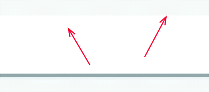
-
1.
Two rays of light from a point source are shown striking a plane mirror . Carefully draw the reflected light rays and locate the image of the point source.

-
2.
The figure below shows a plane mirror and two reflected rays of light.
-
a.
Indicate the location of the point source of light that was the origin of these rays.
-
b.
Draw the incident rays of light associated with the two reflected rays.
-
a.
-
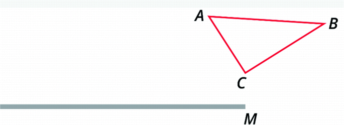
3.
Construct the image of the triangle ABC produced by mirror M. Note that the mirror only extends to a point just below vertex C. (Hint: A complete image of the triangle exists but only for some observers. To find the image, extend the mirror to the right and treat the extension as part of the actual mirror.)
-
4.
Draw the images of the arrow produced by the kaleidoscope.

-
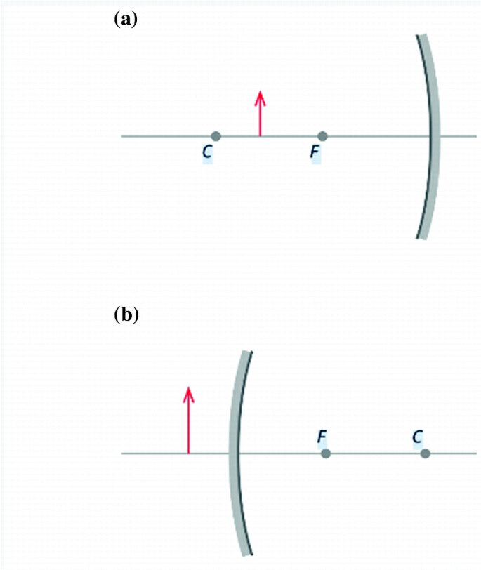
5.
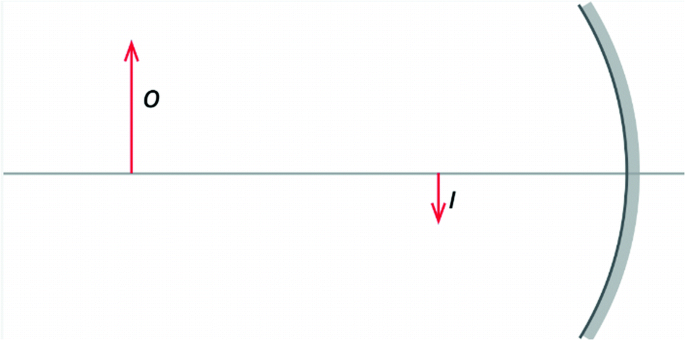
Objects (red arrows) are placed in front of a concave mirror (Fig. a) and a convex mirror (Fig. b). Use ray tracing to locate the images produced by the mirrors.
-
6.
An object and its image formed by a concave mirror are shown in the figure below.
Use ray tracing to locate the focal point and center of curvature of the mirror.
-
7.
How many images of a penny will be produced by a two-mirror kaleidoscope if the angle between the mirrors is (a) 90°, (b) 60°, (c) 45°, (d) 30°?
-
8.
An object is placed 16 cm away from a concave mirror having a focal length of 8 cm.
Using a ruler and compass, make a scale drawing and trace rays to locate the image.
-
9.
If the radius of curvature of a concave mirror is 7 cm, what is its focal length?
-
10.
Using the mirror equation , determine the location of the image formed when an object is placed 25 cm from a concave mirror whose focal length is 5 cm.
-
11.
Apply the mirror equation to find the location of the image produced by a convex mirror having a focal length of −12 cm when the object is placed 12 cm from the mirror.
-
12.
Use Fig. 3.19 to verify that the ratio of image height to object height equals the ratio of image distance to object distance. That is, show that hi/ho = di/do. (Hint: Use a ruler to carefully measure the distances in centimeters.)


● Experiments for Home, Laboratory, and Classroom Demonstration
Home and Classroom Demonstration
-
1.
Seeing ghosts. Careful observation of images produced by a common plane mirror reveals a rather spooky phenomenon: the existence of a faint secondary image adjacent to each principal image. To observe this secondary image, hold an object in front of a mirror. Can you see both images? Compare the appearance of the fainter image to the principal image. How are the two images similar? How do they differ? Do the images change as you view them from various positions? Can you explain the presence of the second image?
-
2.
Curved reflectors. A spoon is actually a double mirror: One side is concave, the other convex. Hold the concave side of a shiny spoon in front of your face. Do you see an image? Is it right-side up or upside down? Is the image enlarged or reduced? Slowly move the spoon away from your face. What do you observe? Now move the spoon toward your face until it is very close to your eye. Does the image ever become blurry? When this occurs, your eye is at the mirror’s focal point . Repeat the preceding steps with the convex side of the spoon. How do the images formed by concave and convex mirrors compare?
-
3.
Examining your car’s mirrors. Examine the mirror on the passenger side of your car. If your car is relatively new, the mirror will more than likely have the following message inscribed on it: “Objects in mirror are closer than they appear.” What does this mean? Examine the type(s) of image(s) produced by this mirror. Is the mirror plane, concave, or convex?
-
4.
Constructing a simple kaleidoscope. Tape the edges of two plane mirrors together to produce a hinge (the reflective surfaces should face each other). Any pair of plane mirrors will work; pairs of small pocket mirrors or larger decorative mirror tiles are good choices. Place an object such as a coin, a small toy, or a drawing or lettering on paper between the mirrors. Observe the images formed by the mirrors. What happens when you make the angle between the mirrors smaller? Larger? Line up a narrow object such as a pencil parallel to one of the mirrors and slowly rotate the second mirror toward the pencil. What happens when the two mirrors become nearly parallel to one another? Have you ever been between parallel mirrors in a hallway or hairdresser’s shop? If so, describe the number of images produced. Using a protractor, adjust the mirrors so that they form a 90° angle. After placing an object between the mirrors, count the images produced. Now count the images produced at 72, 60, and 45°. There is a simple “kaleidoscope equation ” that gives the number of images produced for a particular mirror angle. Can you determine this equation from the data you’ve gathered?
-
5.
A view of infinity. A mirror may form an image of another mirror image. When two plane mirrors face each other, a very large number of images may be formed. This phenomenon is familiar to anyone who has been to a hairdresser’s shop. To experience a view into infinity, hold a small pocket mirror between your face and a second larger mirror. The reflecting surfaces of the two mirrors should face each other. Adjust the mirrors so that they are as close as possible to parallel. When you look around the smaller mirror into the larger mirror, you should see reflections that appear to stretch into the distance. The number of images produced is limited by the absorption of light by the mirrors.
-
6.
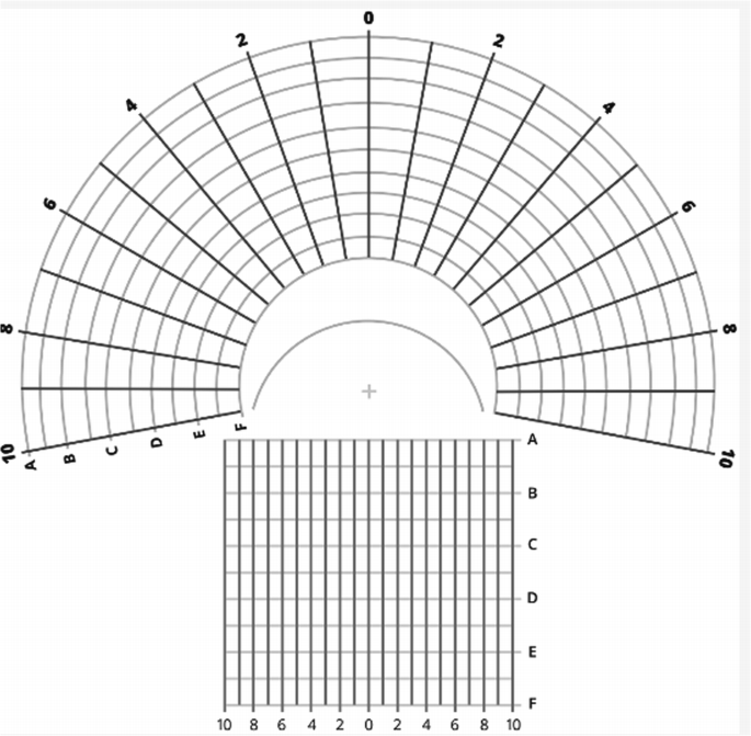
Anamorphic art. Make an enlarged photocopy of the figure shown below. Draw or paint a picture on the rectangular grid, and then map it onto the circular grid by transferring each point on the rectangular grid to the corresponding point on the curved grid. To view your art, place a cylindrical mirror (a section of shiny pipe or can or a sheet of reflecting plastic rolled up into a cylinder) at the spot marked +.
-
7.
Smartphone projection pyramid. Draw a trapezoid, according to the pattern shown below, on a sheet of plastic or discarded CD case.
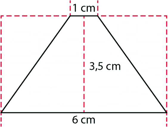
Using scissors, or a utility knife if a CD case is used, carefully cut out the traced trapezoid. Using this piece as a template, produce three additional plastic pieces. Form a pyramid by connecting the sides of the four pieces together with either clear tape or glue. After downloading one of many “pyramid hologram videos” from the internet, place the pyramid on the phone’s screen so that the top of the pyramid rests in the middle of the video’s four images. When a face of the pyramid is viewed from the side, a projected image will be seen that appears to be suspended in air. It should be noted that although the images are often referred to as holographic, they are not. They are simply reflections.
-
8.
Discovering examples of reflection in painting. Examine paintings at art museums and in art books in the library. Note all the cases you find where a painter has used reflections (in mirrors, water surfaces, or otherwise).


Laboratory (See Appendix J)
-
3.1 Shadows and Light Rays
-
3.2 Law of Reflection and Plane Mirrors
-
3.3 Construct a Kaleidoscope
-
3.4 Image Formation by Concave Mirrors
Further Reading
Ernst, Bruno. (1994). The Magic Mirror of M. C. Escher. New York: Taschen America.
Goldberg, B. (1985). The Mirror and Man. Charlottesville: University Press of Virginia.
Hewitt, P. G. (2014). Conceptual Physics, 12th ed. Boston: Pearson.
Kirkpatrick, L. D., & Wheeler, G. F. (1995). Physics: A World View, 2nd ed. Philadelphia: Saunders College Publishing.
McLaughlin Brothers. (ca. 1900). Magic Mirror. Reprinted by Dover, Mineola, NY, 1979.
Miller, Jonathon. (1998). On Reflection. London: National Gallery of London.
Pendergrast, Mark. (2003). Mirror, Mirror: A History of the Human Love Affair with Reflection. New York: Basic Books.
Rossing, T. D. (1990). The Science of Sound, 2nd ed. Reading, MA: Addison-Wesley.
Schuyt, M., & Joost, E. (1976). Anamorphoses: Games of Perception and Illusion in Art. New York: Abrams.
Author information
Authors and Affiliations
Corresponding author
Glossary of Terms
- anamorphosis (anamorphic art)
-
Artistic use of distorted images that require special mirrors to make them intelligible.
- camera obscura
-
A darkened enclosure having an aperture through which light from external objects enters to form an image of the objects on the opposite surface.
- concave surface
-
A surface curved like the inside of a ball.
- convex surface
-
A surface curved like the outside of a ball.
- diffuse reflection
-
Reflection of rays from a rough surface. The reflected rays scatter and no image is formed.
- focus (focal point)
-
A point at which incident rays parallel to the axis of a mirror will cross after reflection.
- image
-
Replica of an object formed by a mirror (or lens).
- kaleidoscope
-
A device that uses two or more mirrors to form symmetrical, colorful images.
- law of reflection
-
The angle of incidence equals the angle of reflection. Ordinarily, both angles are measured from the normal (perpendicular) to the surface.
- magnification
-
The ratio of the size of image to size of object.
- plane of incidence
-
Plane that includes the incident ray and the normal (perpendicular) to the surface.
- reflection
-
Change of direction (with reversal of the normal component) at a surface.
- specular reflection
-
Reflection from a polished surface in which parallel rays remain parallel.
- virtual image
-
An image created by the apparent intersection of reflected light rays when they are extended behind the reflecting surface. A virtual image cannot be projected onto a screen.
Rights and permissions
Copyright information
© 2019 Springer Nature Switzerland AG
About this chapter

Cite this chapter
Rossing, T.D., Chiaverina, C.J. (2019). Ray Optics: Reflection, Mirrors, and Kaleidoscopes. In: Light Science. Springer, Cham. https://doi.org/10.1007/978-3-030-27103-9_3
Download citation
DOI: https://doi.org/10.1007/978-3-030-27103-9_3
Published:
Publisher Name: Springer, Cham
Print ISBN: 978-3-030-27102-2
Online ISBN: 978-3-030-27103-9
eBook Packages: Physics and AstronomyPhysics and Astronomy (R0)