
Abstract
Air dehumidification in humid climates can improve the people’s living environment to promote the life quality and improve working environment significantly to increase production rate and product quality. Desiccants are key materials used in the dehumidification technologies. In this chapter, the conventional solid desiccant materials and different types of desiccant systems are introduced. Furthermore, the performance of solid dehumidification materials is emphatically analysed. In addition, desiccant regeneration methods are summarized, and two examples of their applications are presented in the last part of the chapter, namely the novel solar solid. dehumidification/regeneration bed and solar-powered dehumidification window. This chapter would be helpful for researchers and engineers in this area to exploit the potential applications of solar desiccant technologies in building sector.
Access provided by Autonomous University of Puebla. Download chapter PDF
Keywords
1 Introduction
Hot and humid weather affects people’s comfort, bringing inconveniences to people’s life and work, as well as influences industrial productivity, thus reducing the quality of process products. Taking an example of South China, most time in a year in South China that is humid, its annual average relative humidity is above 70% [1] and the daily average moisture content in the air-conditioning season is 20 g/kg [2]; air dehumidification becomes more and more important in modern life in such an area with the rapid development of economic and increased life quality demand. Currently, the commonly used air dehumidification methods are cooling dehumidification, compressed air dehumidification, liquid absorption dehumidification and solid adsorption dehumidification, or combination of the above dehumidification methods. Meanwhile, some scholars put forward some new dehumidification technologies, such as membrane dehumidification, electrochemical dehumidification, heat pipe dehumidification and heat pump dehumidification [3]. The selection of air dehumidification methods is mainly based on the processed air parameters and environment, and the comparison of common air dehumidification methods is shown in Table 1 [4]. Among different methods, solid adsorption dehumidification has the advantages of large air volume, strong dehumidification capacity, energy-saving, simple structure and no pollution. Solid adsorption dehumidification usually realizes air dehumidification by loading desiccant material in the air flow channel. According to the structure, solid dehumidification includes rotary dehumidification and packed-bed dehumidification. A rotary dehumidifier has a complex structure, high cost, easy running wet, high regeneration temperature (90–150 °C); thus, the use of low-grade heat source is inhibited [5]. Furthermore, its rotating parts make difficult to achieve the process of internal cooling dehumidification and thermal regeneration, which reduce the dehumidification and regeneration performance. Packed-bed dehumidification has the advantages of large air volume, low-grade energy regeneration, easy of achieving internal cooling dehumidification and thermal regeneration, simple structure and maintenance, low noise and reliable operation, etc. [6,7,8].
When the packed-bed is saturated, it needs to be regenerated to achieve the operation cycle. The regeneration performance is one of the most important factors which affect the dehumidification performance of the packed-bed [9]. The traditional regeneration method is the electrical heating regeneration, which regenerates the solid desiccant material of the packed-bed by the air that is directly heated by electrical energy. This regeneration method has the following major disadvantages:
-
(1)
Low regeneration efficiency Two reasons lead to low regeneration efficiency. One is the two-step heating process, i.e. regeneration air is heated firstly by electricity and then solid desiccant material heated by the regeneration air, leading to the decrease in the regeneration efficiency. Another is that in the heating and regeneration process the moisture movement direction in the solid desiccant material is opposite to the heat transfer and therefore further reduces the regeneration efficiency.
-
(2)
Large regeneration energy consumption. The thermal resistance of the solid desiccant material is large, so the heat in regeneration air is difficult to transfer to interior of the dehumidification material, causing most of the heat to be discharged with the air, and the high temperature (greater than 80 °C) of the regeneration process leads to a large loss of energy consumption [10]. After regeneration, the temperature of solid desiccant material is high, so it is necessary to cool the material before performing the further dehumidification. In the system cycle, heat and cold cancel each other out, further increasing the regeneration energy consumption of the packed-bed.
-
(3)
Long regeneration time. Due to the increase in regeneration temperature, the energy consumption of regeneration will increase, and the high temperature will destroy the structure of solid desiccant material; therefore, the regeneration air temperature of electric heating cannot be too high, resulting in its long regeneration time, which is difficult to meet the engineering application.
In order to solve the problems of low efficiency, large energy consumption and long regeneration time, many scholars have proposed new regeneration methods, including solar regeneration, waste heat regeneration, ultrasonic regeneration, electro-osmotic regeneration and microwave regeneration.
Among these new regeneration methods, solar regeneration has a good energy-saving effect, which can effectively alleviate the pollution caused by the burning of fossil fuels, and it will not cause harm to human body.
Taking an example of South China which is a hot and humid area, the annual total sunshine hours in South China ranges from 1200 to 2200 h and solar radiation range is about 4086.6–5225.1 MJ/m2 [10]. Rich solar energy source provides a good environment for the solar regeneration in this area.
2 Desiccant Materials
The solid desiccant material in a solid dehumidification device is a key factor which affects the dehumidification and the regeneration performance. The solid desiccant materials used commonly include the activated alumina, the molecular sieve, the activated carbon and the silica gel, and the basic properties of each solid desiccant material are given as follows:
2.1 Activated Alumina
Activated alumina (Al2O3) is a kind of high microporous particle, which is mainly made of aluminium hydroxide by hydroxyl reaction, and the capillary structure of activated alumina makes the specific surface area of the internal channel is large and has high activity. The specific surface area of activated alumina is about 100–200 m3/g and the pore diameter is 1.5–6 nm, and the adsorption heat is about 3000 kJ/kg. Activated alumina has higher mechanical strength than silica gel [11]. Moreover, it also has stronger adsorption capacity for water molecules, and its capacity on water can reach about 60% of its own weight [12]. Activated alumina can be used for the deep environmental dehumidification. Under experimental conditions, the dehumidification of the activated alumina to the air can reach the air dew point below −70 °C [13].
2.2 Molecular Sieve
Molecular sieve is mainly composed of crystalline silicate or aluminosilicate, which can be divided into micropore (<2 nm), mesoporous (2–50 nm) and macro-porous (>50 nm) according to the size of the pore. Molecular sieves can also be divided into 3A, 4A, 5A, 10X and 13X according to the chemical composition. The skeleton structure of molecular sieve is stable, and it has strong corrosion resistance. In the case of low relative humidity, molecular sieve has a strong dehumidification capacity. Research has shown that at an ambient temperature of 25 °C, a relative humidity of 20%, the maximum adsorption capacity of 5A, molecular sieve is approximately 20% and the maximum adsorption capacity of microporous silica gel is approximately 5% [14, 15]. At the same time, there are some disadvantages of the molecular sieve. In general, the adsorption capacity of molecular sieve is commonly smaller than that of silica gel [16]. Due to the strong adsorption capacity to molecular sieve for water molecules, it is necessary to consume a lot of thermal energy in the regeneration stage to achieve desorption of moisture, resulting in higher heat loss and detrimental to the use of low-grade energy such as solar energy and waste heat [17]. Molecular sieve has strong adsorption to water molecules and has excellent dehumidification performance under low humidity condition, so it is suitable for low-dew-point dehumidification and special goods storage room, precision instrument storage room and other environment with high humidity requirement [18,19,20,21].
2.3 Activated Carbon
Activated carbon contains carbon, oxygen and hydrogen, and carbon accounted for more than 80–90%. The adsorption performance of activated carbon is mainly determined by its micropore. The pore volume of activated carbon is usually 0.25–0.9 mL/g, and the surface area of microporous surface is about 500–1500 m2/g. Measured by BET method, the micropore surface area can reach 3500–5000 m2/g. Activated carbon is non-polar molecule, which is easy to adsorb non-polar adsorbed mass, while water molecule belongs to polar molecule, so the adsorption ability of the activated carbon to water molecule is poor. Adsorption of activated carbon for water molecules is V-type adsorption, it means under low water vapour pressure, the interaction between molecules is weaker, and the adsorption capacity of activated carbon is smaller. When activated carbon adsorbs part of water, the interaction between adsorbate and adsorbate is formed inside the activated carbon and the adsorption of water molecules increases [22]. Activated carbon is generally used in water adsorption process; it can also be used as a solid desiccant material, but it is poor in water absorption when used as a solid dehumidification material.
2.4 Silica Gel
Silica gel is a kind of semi-transparent, non-toxic, non-corrosive solid desiccant material, and its chemical composition is mSiO2·nH2O, which contains a lot of capillary and crystal block structure. The specific surface area of silica gel is 600–700 m2/g, and the average pore size is 3.2–3.5 nm [23, 24]. The adsorption of silica to water is mostly physical adsorption, and the mass of water that it can absorb can reach 40% of its own mass. The moisture of physical adsorption can basically be removed when the regeneration temperature of silica gel is 100 °C; therefore, low-grade heat source can be used to achieve the regeneration of silica gel. In addition, silica gel adsorbs a small amount of water (about 7% of silica gel mass) by chemical adsorption. This part of water needs a higher regeneration temperature to make it desorbed. Silica gel has the advantages of high moisture adsorption capacity, low regeneration temperature, good mechanical properties and stable chemical properties [25]. At the same time, the silica gel has also some disadvantages; for example, many adsorption heats will be released during the process of dehumidification, causing a sharp decrease in its dehumidification capacity in low humidity conditions and cracks when meeting water droplet and so on.
3 Types of Desiccant Systems
Initially in desiccant bed dehumidification system, solid desiccant material was placed in a closed container to dehumidify the air in the container, and then it developed into two types of desiccant bed [26]: (1) Packed-bed. The solid desiccant material is filled in the tower (cylinder) to dehumidify air. This dehumidification process is intermittent, and regeneration of the solid desiccant material in the tower is periodically; neither its operation nor control is convenient. In order to realize continuous air dehumidification, a two-tower dehumidification method has emerged: a tower for air dehumidification and another tower for the solid desiccant material regeneration. After a certain period two towers are converted, interchanging dehumidification process and regeneration process, so it can achieve continuous air dehumidification. However, in the process of air dehumidification, the adsorption heat produced by the solid desiccant material is difficult to be dissipated, which leads to the increase in temperature and the reduction of the dehumidification performance of the packed-bed, so some scholars put forward a new desiccant device. (2) Desiccant-coated dehumidification packed-bed: the solid desiccant material is fixed on the air channel to dehumidify air. Due to the low thickness of the solid dehumidification material, the adsorption heat is easy to dissipate, which effectively reduces the influence of adsorption heat on the bed dehumidification performance. In order to further reduce the influence of adsorption heat, some scholars have proposed a packed-bed with cooling gas on the other side of the dehumidification channel, which can reduce the temperature and improve the dehumidification performance of the bed [27, 28], and then the fin tube with cooling water is added in packed-bed, which strengthens the heat transfer inside the packed-bed, to further improve the performance of the desiccant bed [29,30,31].
3.1 Packed-Bed
The domestic and foreign researchers have studied the dehumidification performance and dehumidification model of packed-bed. In the aspect of dehumidification performance of the packed-bed, Kabeel [32] studied and analysed the effects of air temperature, humidity, airflow velocity and bed thickness on the dehumidification performance of the packed-bed in the dynamic operation, which is with eight layers, and the results showed that the dehumidification quantity of the packed-bed mainly depended on the humidity of inlet air and air velocity. Song et al. [33] studied the dehumidification performance of packed-bed with different desiccant material filling modes, and they found that the average dehumidification capacity of two pieces of 50-mm-thick, 100-mm-filled desiccant modules was 16.8% greater than that of one piece of 100-mm-thick desiccant module. It is indicated that the dehumidification performance of packed-bed could be improved effectively by the sectional dehumidification of the thickness direction. In order to reduce the effect of adsorption heat on the dehumidification performance of the desiccant material in the thickness direction, the gas–liquid heat exchanger was set in the middle of the packed-bed to reduce air temperature. Ramzy et al. [34] produced a packed-bed with intercooling and compared traditional packed-bed with the experimental one. The results showed that the dehumidification capacity of the packed-bed via intercooling is 22% larger than that of the traditional packed-bed.
In the dehumidification model of the packed-bed, Pesaran and Mills [35] established a solid-side resistance model (SSR) and a pseudo-gas-side-controlled model (PGC) to study the law of water transfer in the dehumidification process of the packed-bed. The results showed that the model calculated with the solid-side resistance was closer to the experimental data. In order to study the effect of heat transfer along the thickness direction of the packed-bed in the process of non-isothermal dehumidification, Ramzy et al. [36] established a solid-side resistance with axial heat conduction model (SSR-AC) that considers the direction heat transfer of the thickness of the bed based on the solid-side resistance model. And by comparing the calculation results of SSR model and SSR-AC model, the effect of heat transfer along the thickness direction of the packed-bed in the dehumidification process was studied. Ramzy et al. [37] established the pseudo-gas-side-controlled (PGC) mathematical model and compared with the experimental results. The results showed that the root mean square of errors ranges from 1.15 to 9.03% for the exit air humidity ratio and from 1.08 to 9.68% for the exit air temperature. By using the scale principle to analyse and calculate the heat and mass transfer process of the desiccant in the packed-bed and comparing with the numerical simulation results of the packed-bed dehumidification process, Mitra et al. [38] found that the scale principle can accurately describe the two-dimensional heat and mass transfer process of the packed-bed dehumidification, which provides the theoretical basis for the establishment of the packed-bed dehumidification model.
3.2 Desiccant-Coated Dehumidification Packed-Bed
The research on the desiccant-coated dehumidification packed-bed at home and abroad mainly includes the dehumidification performance and the dehumidification model. In the aspect of the dehumidification performance of desiccant-coated dehumidification packed-bed, Ge [39] carried on the experimental research on the dehumidification performance of the cross-flow packed-bed and downstream-flow packed-bed. The results showed that the dehumidification capacity of the cross-flow packed-bed is greater than that of downstream-flow packed-bed, but there is a large heat resistance between the dehumidification material in the cross-flow packed-bed, resulting in the difference between the temperature of inlet and outlet air of the cross-flow packed-bed is greater than that of the downstream-flow packed-bed. In order to study the effect of air channel structure on the dehumidification performance of the packed-bed, based on the turbulent boundary layer theory, Feng et al. [40] designed three types of packed-beds, including the straight channel type packed-bed, the curved channel type packed-bed and the spiral channel type packed-bed, and carried on the experimental research. The results showed that the spiral channel structure had the most obvious effect on improving the motion of water molecules on the surface of the desiccant material, so the spiral channel structure had the best dehumidification effect. In order to reduce the effect of adsorption heat on the dehumidification performance of the packed-bed in dehumidification process, Worek and Lavan [41] glued silica gel on the dehumidification channel and passed the cooling gas on the other side of the channel, setting up a cross-cooled desiccant dehumidifier with cooling gas channel. The results showed the dehumidification capacity of the cross-cooled desiccant dehumidifier was 30–60 g/kg. Fathallah and Aly [42] improved the dehumidification performance of cross-cooled desiccant packed-bed. Dehumidification channel was filled with silica gel, which improved dehumidification capacity of cross-cooled desiccant packed-bed, but this method increased the heat resistance of the dehumidification material in dehumidification channel, going against to the adsorption heat dissipation. Yuan et al. [28] stick the solid desiccant material on the air channel of the plate-fin heat exchanger to produce a cross-cooled compact solid desiccant dehumidifier and compared the cross-cooled desiccant dehumidifier with it, and the results showed that the dehumidification performance of the cross-cooled compact solid desiccant dehumidifier is better than that of cross-cooled desiccant dehumidifier. Under the high humidity condition, the dehumidification rate of cross-cooled compact solid desiccant dehumidifier can reach 12.4%. The dehumidifier can use the gas–solid heat exchange to eliminate the adsorption heat generated by the solid desiccant material; however, with this heat exchange method it is difficult to improve the thermal efficiency. Peng et al. [29] proposed the method of liquid–solid heat exchange to eliminate the adsorption heat that produced by solid desiccant material. They stick the solid desiccant material on outer surface of the finned tube and pipe of heat exchanger and passed cooling water in the pipes. The results showed that when the inlet air temperature was 24.7 °C and the moisture content was 12.41 g/kg, the dehumidification rate of finned tube packed-bed can reach 43.8%.
In the dehumidification model of the desiccant-coated dehumidifier, Yuan et al. [28] established the dynamic dehumidification model of the cross-cooled compact solid desiccant dehumidifier by the finite difference method, and the results showed that the error between simulation results and experimental results was less than 7%. Zhao et al. [43] studied the heat and mass transfer law of the gas side in the finned tube packed-bed dehumidification process through experiments under conditions of a different air temperature, humidity, velocity and cold water temperature, the NU number and SH number of the finned tube packed-bed dehumidification process under various operating conditions are obtained, which provided a theoretical basis for the establishment of the finned tube packed-bed dehumidification model. Ge et al. [31] established the mathematic model of the finned tube packed-bed in dehumidification process, and the operation of the packed-bed was simulated by C++ language program and compared with the experiment, which showed that the error between the simulation results and the experimental results was less than 15%.
The current research status of packed-bed dehumidification is mainly focused on the improvement of dehumidification performance and establishment of dehumidification model. The desiccant-coated dehumidifier provides an effective cooled method for dehumidification process, most of the adsorption heat created in the dehumidification process can be taken, which effectively improves the dehumidification performance of the packed-bed. But the effective dehumidification time of most desiccant-coated dehumidifier is short, which cannot meet the engineering application, and the dehumidification/regeneration switching time is too short leading to energy waste. Nowadays, packed-bed dehumidification is more common, which can deal with large amount of air and have a long effective dehumidification time, but because the solid desiccant material is loaded in the form of accumulation, the adsorption heat produced in the dehumidification process is difficult to disperse, which leads to the decrease in the dehumidification performance of packed-bed.
4 Performance of Solid Dehumidification Materials
The physical properties of solid desiccant materials have important effects on their internal heat and moisture transfer. Solid desiccant material silica gel with two kinds of phase change materials, GR50 and PK52, were investigated; their basic performance parameters such as bulk density, porosity, thermal conductivity and radiation transmittance of solid dehumidification materials and phase change materials were tested, which provide a reference for solid dehumidification bed simulation and structural optimization.
4.1 Density Measurement
In this section, the density of the solid desiccant materials used in the experiments was measured by a graduated cylinder method and verified by a mass-volume method. The equipment used in the test includes electronic balance, electric blast oven and cylinder. The performance parameters of each test instrument are shown in Tables 2 and 3.
-
(1)
Test results from cylinder method
The material bulk density test results are listed in Tables 4, 5, 6, 7 and 8.
Table 4 Experimental test results of silica gel density Table 5 Experimental test results of PK52 phase change materials Table 6 Experimental test results of GR50 phase change materials Table 7 Test results of PK52 phase change materials and silica gel compound Table 8 Test results of GR50 phase change materials and silica gel compound It can be seen from the above test that the density of the two kinds of phase change materials is basically in line with the nominal value. GR50 had an error of 2.01% and PK52 had an error of 8.2%, which reflects the accuracy of the test results. In order to further verify the density accuracy of the dehumidification material, the mass-volume method is used for further calculation.
-
(2)
Test results from mass-volume method
To correct the volume of the dehumidification and phase change mixture material, the mass-volume method was applied according to Eq. (1). The materials were homogeneously hybrid and placed in a rigid three-dimensional module with a length × width of 400 mm × 340 mm. The surface of the desiccant material was gently flattened by plate, and the thickness was measured at nine random points. The thickness of each point is listed in Table 9, and the basic test parameters for silica gel + PK52 hybrid material and silica gel + GR50 hybrid material are shown in Table 10.
$$\rho = \frac{m}{v}$$(1)Table 9 Thickness parameters of hybrid materials Table 10 Bulk density test parameters of hybrid materials It can be calculated from the known data and Eq. (1) that the average density of silica gel + PK52 hybrid material is 746.6 kg/m3. Similarly, the average density of silica gel + GR50 hybrid material is 896.9 kg/m3, which is in accord with the results obtained by measuring cylinder method.
4.2 Porosity Calculation
The porosity of material is the percentage of the pore volume of the material in the unit of the original material [44], defined by:
where \(\Gamma\)—the porosity of the material, %; Vp—the pore volume of the material, cm3; V0—the total volume of the material, cm3; Vs—the material dense solid volume, cm3.
Like porosity, the relative density \(\rho_{\text{r}}\) is the ratio of the apparent density of the porous material to the density of the corresponding dense material. The relationship between relative density \(\rho_{\text{r}}\) and porosity \(\Gamma\) is as follows [45]:
where \(\rho_{\text{r}}\)—the relative density of the material, g/cm3; \(\rho^{*}\)—the apparent density of the material, g/cm3; \(\rho_{\text{s}}\)—the dense density of the material, g/cm3.
Methods for measuring the porosity of common materials include [45]: (1) microscopic analysis; (2) mass-volume direct calculation method; (3) soaking medium method; (4) vacuum impregnation method; (5) floating method. In this paper, the adsorption medium is loose material, and formula (2) was applied to calculate the porosity of the material. The results showed that the porosity of silica gel is 0.34–0.4 L/kg and the bulk density of silica gel is 1034 kg/m3, so the porosity of silica gel is 35.12–41.36%.
4.3 Thermal Conductivity Measurement
-
(1)
Measurement method
The heat transfer in the solid desiccant material is a combination process of thermal and moisture migration effects. In order to explain the mechanism of the material’s thermal conductivity and mass transfer, the thermal conductivity of the solid desiccant material with different moisture contents is tested with the DRM-II thermal conductivity meter, as shown in Fig. 1, and the specific instrument performance parameters are shown in Table 11.

The DRM-II coefficient of thermal conductivity tester
There are two different test methods for thermal conductivities of solid desiccant materials: steady-state method and unsteady method. The unsteady plane heat source method can be applied to measure homogeneous solid materials, heterogeneous materials and porous materials. The material thermal conductivity, specific heat capacity and other thermal properties can be obtained at the same time by only measuring the temperature changes in a sample. The following thermal conductivity tests were carried out to measure the thermal conductivities of silica gel, silica gel + PK52 hybrid material and silica gel + GR50 mixture, respectively. For the above materials, the interspace between the particle skeletons is mostly interconnected, and the fluid could pass through; therefore, it belongs to a typical porous medium [46]. The main steps of the test are as follows:
-
(1)
The dehumidification material samples with the same ratio were divided into two groups for two different tests; each group includes three pieces: one is a thin specimen (200 mm × 200 mm × 20 mm) and the other two are thick specimens (200 mm × 200 mm × 100 mm). The thickness of the specimen is uniform, and the unevenness of the thin specimen shall be less than 1% of its thickness.
-
(2)
Two different tests were carried out for the two groups of the samples, respectively. One test was the natural wet performance test, and another was performance test in the artificial humidification state. For the natural wet performance test, the pure silica gel was placed in a drying oven with a temperature of 140 °C, and the time for drying was at least 4 h so that the physical adsorption water can be taken out, and then the silica gel was cooled to the room temperature to be tested for its performance. For the performance test in the artificial humidification state, the test was carried out using the method of artificial humidification to dry the specimen to the required humidity and the moisture content change within the material was measured by a humidity meter. For each group of test pieces, the humidity difference should be less than ± 1%, and the humidity in the same specimen should be evenly distributed to study the thermal performance parameters of the material under different humidification conditions.
-
(3)
Put the samples in the test device. When the test dehumidification temperature changes within 5 min, temperature is less than 0.05 °C, and the temperature difference between the upper and lower surface of the thin specimen is less than 0.1 °C, that is, the beginning of the measurement.
To verify the test results, Eq. (4) [47] is used to calculate the theoretical thermal conductivity of the materials in different humidity conditions.
where λwet—the thermal conductivity of the material in the wet state, W/(m K); λdry—the thermal conductivity of the material in the dry state, W/(m K); φ—the moisture content of the material, %; λw—the thermal conductivity of water, W/(m K).
-
(2)
Thermal conductivity test results
-
1.
Silica gel
The test results of the thermal conductivity of pure silica gel were obtained. The moisture content varies from 0 to 21.2%. The test results and theoretical calculation results are shown in Table 12.
Table 12 Testing and theoretical equivalent coefficient of thermal conductivity of silica gel It can be seen from Table 12 and Fig. 2 that the thermal conductivity test results of pure silica gel material are in accord with the calculated values, and the thermal conductivity increases linearly with the moisture content. The correlation between the thermal conductivity and the moisture content is shown in Table 13. As shown in Table 12, the measured value of the thermal conductivity and the theoretical value are consistent, the relative error is between 0.29 and 6.84%, and the absolute error is about 0.001–0.018 W/(m K).
Fig. 2 
Theoretical and measured value of thermal conductivity of silica gel
Table 13 Correlation of silicone between thermal conductivity and moisture rate -
2.
Silica gel + PK52 hybrid materials
The thermal conductivity of silica gel + PK52 hybrid materials was tested. The moisture content varies from the natural dry state to 20.0% (moisture content 0–20.0%). The test results and theoretical calculation are shown in Table 14. The correlation between the thermal conductivity and the moisture content is shown in Fig. 3, and the thermal conductivity changed with moisture content is shown in Fig. 4.
Table 14 Correlation of thermal conductivity and moisture content of the silica gel + PK52 hybrid materials Fig. 3 
Theoretical and measured value of thermal conductivity of the silica gel + PK52 hybrid materials
Fig. 4 
Theoretical and measured value of thermal conductivity of the silica gel + PK52 hybrid materials in low moisture rate condition
In the state of moisture content that is below 20%, the thermal conductivity of silica gel + PK52 hybrid material is linearly increasing with moisture content (see Fig. 4 and Table 14). This is because when the moisture content is about below 12%, the pores have a larger flow area, and the diffusion of steam by the wall dehumidification contains less. The smaller the internal air content of the material, the greater the heat and mass exchange coefficient, so the thermal conductivity increases with the increase in the moisture content [48]. When the dehumidification material is in the near saturation state, the material shows non-dehumidification and gradually produces water, the heat and mass exchange coefficient becomes smaller, and the thermal conductivity decreases. There should be a critical moisture content, at which the dehumidification of the dehumidified material has the strongest influence, the heat and mass exchange coefficient is the largest, and the thermal conductivity is the largest. Analysis of the test data shows that the critical moisture content is 15%. It could be inferred from Table 15 and Fig. 4 that the relative error between the theoretical thermal conductivity and the actual test results was between 1.99 and 15.2%. In the case of moisture content ≤12%, the theoretical thermal conductivity was consistent with the experimental data, the minimum deviation was 1.99%, and the maximum deviation was 9.66%. In the case of moisture content >12%, the calculation results of the theoretical thermal conductivity differed much from experimental data, with the maximum deviation of 15.2%.
Table 15 Theoretical and measured thermal conductivity of hybrid materials -
3.
Test for the thermal conductivity of silica gel + GR50 hybrid material
The test results of thermal conductivity of silica gel + GR50 hybrid material were obtained. The moisture content varies from the natural dry state to 15.8%. The test and theoretical calculation results for the thermal conductivity at different moisture contents are listed in Table 16. The thermal conductivity changes with the moisture content are shown in Fig. 5.
Table 16 Theoretical and measured thermal conductivity of silica gel + GR50 hybrid materials Fig. 5 
Theoretical and measured value of thermal conductivity of the silica gel + GR50 hybrid materials
It can be seen from Fig. 5 and Table 17 that the thermal conductivity test results of the silica gel + GR50 mixture tend to be consistent with the theoretical calculated values (relative error <10%), and the thermal conductivity changed with moisture content linearly. The surface of the GR50 material was wrapped with a layer of soil-like material, and the material itself could absorb water when the moisture content reaches 15.8%. Compared to PK52, when the moisture content is more than 12%, the internal pores of the material still have a large circulation area. The diffusion of steam was less affected by the dehumidification of the wall. The greater the moisture content, the more moisture content of the material, the smaller the air content inside the material, the heat and mass exchange coefficient becomes larger, so the thermal conductivity increases with the increase in the moisture content (Table 17).
Table 17 Correlation of silica gel + GR50 hybrid materials between thermal conductivity and moisture rate


4.4 Solar Radiation Penetration Test
-
(1)
Test rigs and test method
In this test, the thickness of the material with the internal temperature that reaches 60% of the surface temperature is defined as the effective layer for solar radiation. The ratio of the temperature of the material at different thicknesses to its surface temperature is defined as the solar radiation transmittance. The experimental device shown in Fig. 6 was used to test the transmittance of the material, and length × width × thickness of the dehumidification bed is 400 × 350 × 200 (mm). To reduce the impact of heat transfer to the surrounding environment, a 50-mm-thick extruded polystyrene board was used as the insulation, the upper part of the dehumidification bed with double vacuum glass as a cover with glass glue to seal. A sun radiation simulator was set at 500 mm from the surface of the dehumidifying material, and the average thickness of the dehumidifying material was 150 mm. The oblique diagonal 1/3, 2/3 division points on the dehumidified bed were selected as the experimental points, and 14 temperature measuring points were arranged every 20 mm in the vertical height direction of the dehumidifying material to measure the temperature of the material at different thicknesses. The voltage of the solar radiation simulator was adjusted to obtain the transmittance of the dehumidified material under different simulated solar radiations. The temperature was collected every 5 min and the test last for 5 h each day, and the specification of the instrument for measurement is shown in Table 18.
Fig. 6 
Solar radiation penetration test system
Table 18 Specification of instruments -
(2)
Test results of solar penetration rate
-
1.
Penetration rate of pure silica gel
The temperature and radiation transmittance curves of the pure silica gel at different solar radiation intensities are shown in Figs. 7, 8, 9, 10, 11 and 12.
Fig. 7 
Temperature of desiccant bed in the 350 W/m2 radiation intensity
Fig. 8 
Temperature of the desiccant bed in the 750 W/m2 radiation intensity
Fig. 9 
Temperature of the desiccant bed in the 1150 W/m2 radiation intensity
Fig. 10 
Penetration rate of the desiccant bed in the 350 W/m2 radiation intensity
Fig. 11 
Penetration rate of the desiccant bed with 750 W/m2 radiation intensity
Fig. 12 
Penetration rate of the desiccant bed with 1150 W/m2 radiation intensity
It can be seen from the above test results:
-
(1)
The surface and internal temperatures of pure silica gel material increased with the test time, and the growth rate of the surface temperature was obviously larger than the internal temperature growth rate within the first 1 h. The penetration rate was declining with time.
-
(2)
Under different solar radiation intensities, the surface temperature of the dehumidified bed and the temperature curve at 2 cm thickness were convex curve. The temperature of the 4 cm thickness material increased linearly with time, and the temperature curves of 4 cm and below had concave trend.
-
(3)
The heat transfer at the bottom of the dehumidification bed is hysteresis. The smaller the solar radiation is, the more obvious the hysteresis effect of the pure silica material. During the experiment, the transmittance of pure silica gel was decreased obviously from 0 to 0.5 h mainly due to the rapid increase in the surface temperature of the xenon lamp in the form of radiant heat, and then the heat transfer from the surface of the pure silica material to the bottom. The larger the thickness of the measuring point, the longer the duration of the decline in penetration, the more obvious the rate of decline. This phenomenon reflects the heat transfer along the thickness of the hysteresis effect, the thicker the material, the more significant the hysteresis effect.
-
(4)
Pure silica gel material had a high transmittance at a thickness of less than 4 cm, and the transmittance changed linearly with time when the transmittance was stabilized.
-
(5)
The temperature rise rate at the bottom of the material was smaller than the temperature rise rate at the upper part of the material, and the rate of penetration growth at the bottom of the material was higher than the rate of penetration growth at the upper part of the material. Comparison of the material temperature and permeability difference under different radiation intensities showed that the maximum difference is between the thickness of 4 and 6 cm. For the radiation intensity of 750 W/m2, the temperature difference at 4 and 6 cm was 12 °C and the penetration difference was 20%.
-
(1)
-
2.
Solar penetration rate of silica gel + PK52 hybrid material
The variation of internal temperature and permeability of the silica gel + PK52 hybrid material with time for different solar radiation intensities is shown in Figs. 13, 14, 15, 16, 17, 18, 19 and 20; and Table 19.
Fig. 13 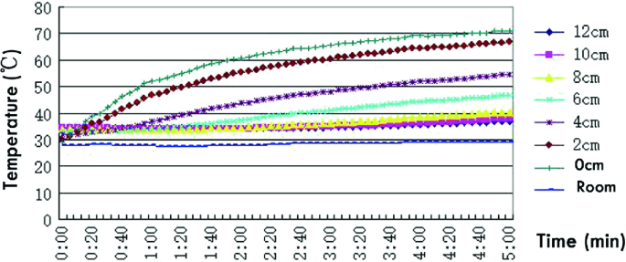
Temperature of silica gel + PK52 hybrid material with 360 W/m2 radiation intensity
Fig. 14 
Temperature of silica gel + PK52 hybrid material with 600 W/m2 radiation intensity
Fig. 15 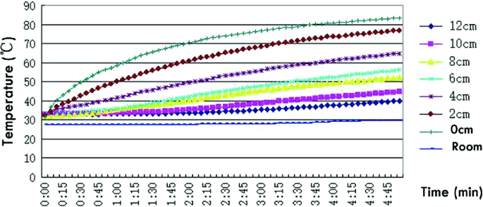
Temperature of silica gel + PK52 hybrid material with 1000 W/m2 radiation intensity
Fig. 16 
Penetration rate of silica gel + PK52 hybrid material with 360 W/m2 radiation intensity
Fig. 17 
Penetration rate of silica gel + PK52 hybrid material with 600 W/m2 radiation intensity
Fig. 18 
Penetration rate of silica gel + PK52 hybrid material with 1000 W/m2 radiation intensity
Fig. 19 
Temperature of 4 cm thickness hybrid material in different radiation intensity
Fig. 20 
Temperature of 6 cm thickness silica gel + PK52 hybrid material in different radiation intensity
Table 19 Relationship of penetration rate changes with time in hybrid material layer The test results have been analysed, and the following conclusions have been obtained:
-
(1)
Silica gel + PK52 hybrid material itself could storage heat. At the start of the test, the penetration rate of the material was 100%. The internal temperature of the material was higher than that of the surface, indicating that the external heat dissipation temperature of the material surface was reduced during the test, and the internal temperature was changed by the phase change material. The phase change material slowly solidified and phase change latent heat was released, resulting in the material’s higher internal temperature than the surface temperature.
-
(2)
The variation of the temperature at the surface and 2 cm and 4 cm thickness of the material under different solar radiation intensities with time showed slightly convex curve growth, the temperature rise rate gradually decreased, the temperature at thickness below 6 cm increased linearly with time, and the rate of material temperature rise decreased as the thickness increased.
-
(3)
The smaller the solar radiation, the more obvious hysteresis effect of the material. With the same radiation intensity, the larger the thickness, the larger the heat lag effect. After the penetration rate was stabilized, the transmittance increased linearly with time. The linear growth slope of 4 and 6 cm thickness was the largest, and the linear relationship of transmittance change at 2 and 4 cm with time is shown in Table 19.
Table 20 Relationships between penetration rate and time in silica gel + GR50 hybrid material layer
-
(1)
-
3.
Solar penetration rate of silica gel + GR50 hybrid material
Variation of temperature and permeability of silica gel + GR50 hybrid material with time for different solar radiation intensities is shown in Figs. 21, 22, 23, 24, 25 and 26. The relationship between the permeability rate and time at 2 cm and 4 cm thickness is shown in Table 20.
Fig. 21 
Penetration rate of silica gel + GR50 hybrid material in 500 W/m2 radiation intensity
Fig. 22 
Penetration rate of silica gel + GR50 hybrid material in 750 W/m2 radiation intensity
Fig. 23 
Penetration rate of silica gel + GR50 hybrid material in 1100 W/m2 radiation intensity
Fig. 24 
Penetration rate of silica gel + GR50 hybrid material in 500 W/m2 radiation intensity
Fig. 25 
Penetration rate of silica gel + GR50 hybrid material in 750 W/m2 radiation intensity
Fig. 26 
Penetration rate of silica gel + GR50 hybrid material in 1100 W/m2 radiation intensity


4.5 Preparation of Dehumidification Material
The silica gel with diameter of 2–4 mm and the phase change material particles with the similar diameter were selected. With the phase change medium added, the vaporized latent heat released from the water vapour in the treated air can be absorbed, thereby reducing the sensible heat load. Phase change material can absorb heat in the dehumidification process and release heat in the regeneration process, forming a melting–condensation cycle process.
After the comparison of the performance requirements of the material, PK52 and GR50 were selected as the phase change medium. They were mixed with the silica gel as the dehumidification material to be tested. The parameters of the material are shown in Table 21.
Referring to the summer outdoor temperature, relative humidity and dehumidification capacity in Guangzhou (a city in South China), melting point of about 50 °C is suitable. The thickness of the dehumidification material was calculated based on the optimum thickness of the bed of the dehumidification bed (5 cm), and the mass ratio of the dehumidifying material and the phase change material was determined by the dehumidification capacity of the dehumidification material and the amount of latent heat released. The experiment was carried out in Guangzhou at room temperature 34 °C and relative humidity 75%. It was known that the moisture content d = 25.2 g/kg, the average density ρ = 1.132 kg/m3, the size of the duct is the length × width = 0.3 m × 0.25 m, the vaporized latent heat of the water vapour at 34 °C is 2415 kJ/kg, the adsorption rate of silica gel was 30%, effective dehumidification rate was 80%, and wind speed v = 1.5 m/s. It can be obtained that the air mass flow was 458.35 kg/h, the theoretical unit of silica gel adsorption capacity was 0.216 kg/kg, latent heat release per unit time was 1506.6 kJ/h, and the weight of dehumidification material was 6 kg. Considering the system of air leakage loss and heat loss [18], the correction factor 0.7 was applied, and the heat needed to be absorbed by that phase change material was 1054.62 kJ/h. It could be inferred from Table 21 that the storage density of phase change material was 131 kJ/kg, so 8 kg phase change material needed to be added, and mass ratio of silica gel/phase change material was 3:4.
5 Desiccant Regeneration Methods
The traditional regeneration method of the solid dehumidification packed-bed is electric heating regeneration; the principle is to use the air directly heated by electric energy to regenerate the packed-bed. However, it has the disadvantages of low efficiency, high energy consumption and long regeneration time [49], so this kind of regeneration method cannot meet the engineering applications and the increasingly urgent energy-saving requirements. To solve the above problems effectively, it is vital to develop the solid dehumidification packed-bed. New regeneration methods of the solid dehumidification packed-bed are needed to control and reduce the regenerative energy consumption, improve the regenerative efficiency, save the operating cost and meet the inevitable requirements of energy-saving and emission reduction. Aiming at the problems of low regeneration efficiency, large energy consumption and long regeneration time of electric heating regeneration, many researchers have proposed the new regeneration methods that include waste heat regeneration, ultrasonic regeneration, electro-osmotic regeneration, microwave regeneration and solar regeneration.
5.1 Waste Heat Regeneration
The waste heat regeneration system of solid dehumidification packed-bed is reformed based on original production system, combining the heat transfer equipment with the packed-bed, and the basic principle is to use the waste heat generated from the production process to heat and regenerate the packed-bed. At present, the waste heat which is commonly used mainly includes the waste heat of air-conditioning system and industrial waste heat. Under the normal circumstances, the temperature of the equipment is relatively low when the air-conditioning system is in the operation, and the hot air generated by the heat exchange has a low temperature. Therefore, it is commonly used for the preheating of the packed-bed regeneration. Zhao et al. [50] designed a system, which could recover the exhaust heat of air-conditioning system for preheating the regeneration of the packed-bed, effectively improving the COPh of dehumidification cooling system. Compared to the compressed air-conditioning system, high temperature hot water can be produced by the operating process of the absorption air-conditioning system. Fathallah and Aly [42] designed a kind of waste heat regeneration system, which used the waste heat from condenser of the absorption refrigeration unit to regenerate the packed-bed, so the temperature of regeneration air was increased to 73 °C, which can be used directly for regeneration. In the use of the packed-bed regenerated by industrial waste heat, the US Department of Energy has developed an integrated energy system (IES) which uses the waste heat from the generator to regenerate the packed-bed. The system was reported by Zaltash et al. [51]. Myat et al. [52, 53] used the waste heat from factory to regenerate the multi-layer packed-bed, and in the process, they used the 55–80 °C hot water, which is heated by the factory waste heat, to achieve the regeneration of the multi-layer packed-bed.
The waste heat regeneration method has the advantages of energy-saving, stable effect and no need of auxiliary heating equipment, which can effectively improve the energy efficiency and stability of the packed-bed regeneration. However, the research and application of the packed-bed waste heat regeneration are limited by the heat source place, it is difficult to popularize, and the heat exchange equipment, which is suitable for utilizing the waste heat in various industries, is still in the research stage, resulting in waste heat regeneration mode only applicable for the production of 60–140 °C waste heat site [7].
5.2 Ultrasonic Regeneration
Ultrasonic regeneration is to use the mechanical effect and thermal effect produced by super acoustic wave to strengthen the regeneration of the packed-bed. On the one hand, the mechanical vibration effect produced by ultrasonic wave propagates in the solid desiccant material, causing severe air disturbances in the pores of solid desiccant materials, destroying the surface water vapour film of the solid desiccant material, thus reducing the gas-side mass transfer resistance of solid desiccant materials. On the other hand, the heat effect caused by ultrasonic wave increases the internal temperature of the dehumidification material, speeding up the migration of internal moisture to the outer surface, thus increasing the gas-side mass transfer power of the dehumidification material [54, 55]. Many scholars have studied the regeneration characteristics, regeneration mechanism and regeneration model of ultrasonic regeneration packed-bed.
In terms of the regeneration characteristics of ultrasonic regeneration packed-bed, Yao et al. [56, 57] studied about the influence factors of ultrasonic regeneration packed-bed, including the regeneration air temperature, the moisture content of solid dehumidification materials, the ultrasonic power and frequency; then the results showed that the efficiency of the ultrasonic regenerative packed-bed increased with the decrease in regenerative air temperature and increased with the increase in the water ratio of silica gel. The results also showed the regeneration rate of the ultrasonic regenerative packed-bed increased with the increase in ultrasonic power and decreased with the increase in ultrasonic frequency, and the influence of ultrasonic power and frequency change increased with the decrease in regenerative air temperature. Yao et al. [57] found that the regenerative energy consumption of the ultrasonic regenerative packed-bed decreased with the increase in ultrasonic power and increased with the increase in ultrasonic frequency; in further research and analysis [58], they found that the regenerative energy consumption of the ultrasonic regenerative packed-bed depended mainly on the regeneration condition of the packed-bed, and the SEC index was proposed to evaluate the energy-saving characteristics of ultrasonic regenerative packed-bed under different regeneration conditions, by calculating the different regenerative air temperatures, and ultrasonic power of the SEC can find the best energy-saving conditions, which provided the theoretical basis for the selection of the working condition of the packed-bed with ultrasonic regeneration.
In the regeneration mechanism of ultrasonic regenerative packed-bed, through theoretical analysis, Yao et al. [55] found that the mechanical effect and thermal effect of ultrasonic wave can not only improve the moisture diffusion rate of silica gel regeneration, but also reduce the activation energy that required for the internal moisture removal of silica gel, consequently reducing the regeneration temperature and improving the availability of low-temperature heat source in the process of packed-bed regeneration. Yang et al. [59] used two kinds of silica gel (M and SS type) as dehumidification material, to study the mechanical effect and thermal effect on promoting regeneration process, and the research results showed that the thermal effect on promoting the regeneration process was less than 14% (m type) and 20% (SS type), which was shown that the ultrasonic regenerative process of the packed-bed was mainly promoted by mechanical effect. Yao et al. [60] studied the mechanism of ultrasonic mechanical effect and heat effect on the regeneration process; they found that the mechanical effect of ultrasound enlarged the synergy between the surrounding velocity field and the temperature field of silica gel particles, effectively promoted the convection heat and mass transfer effect of the air side and improved the regeneration rate of silica gel; the thermal effect of ultrasound promoted the diffusion of moisture and temperature in silica gel and increased the rate of silica gel regeneration.
In the regeneration model of the packed-bed with ultrasonic regeneration, Yao et al. [57, 61] used six models (Page model, Lewis model, Henderson model, Logarithmic model, Gaussian model and Weibull model) to simulate and analyse that water ratio variation with time in the process of ultrasonic regeneration. The results showed that the regeneration rate constants of the Weibull model did not vary with the regeneration condition, while the regeneration rate constants of the other models varied with the regeneration condition, so the Weibull model was more suitable for the change of silica gel moisture ratio with time during the simulated ultrasonic regenerative packed-bed process. On the basis of ultrasonic mechanical effect and thermal effect mechanism, Yao et al. [62, 63] proposed one dimensional transient heat and mass transfer model of ultrasonic combined with hot air regenerative packed-bed, and the theoretical value of the model calculation was compared with the experimental value, the results showed that the average relative error between the theoretical and experimental values was less than 2%, and it showed that the model could simulate the heat and mass transfer process of ultrasonic combined with hot air regenerative packed-bed well.
Ultrasonic regeneration has the advantages of high regeneration rate, small regenerative energy consumption, low regenerative temperature, and so on; at the same time, ultrasonic also has bactericidal function and can effectively reduce the solid desiccant materials and airborne bacteria concentration. However, ultrasonic regeneration has not been popularized in practical application, and most of the research remains in the laboratory stage. On the one hand, it is because the cost of the equipment is 2–3 times higher than that of the electric heating regeneration; on the other hand, it is difficult to meet the application requirement because of the production process of sonic generator; in the mechanism of ultrasonic regeneration, mechanical effect and thermal effect have been studied, while the effect of ultrasonic cavitation on the packed-bed ultrasonic regeneration is rarely reported. The results show that the cavitation effect of ultrasonic wave is the main power of ultrasonic chemistry, and the shock wave, microjet and microdisturbance are the main mechanism of strengthening ultrasonic drying in the fields of food and medicine. Therefore, it is necessary to study the effect of ultrasonic cavitation effect on the ultrasonic regenerative packed-bed [56, 64, 65].
5.3 Electro-osmotic Regeneration
The electro-osmotic regeneration is to regenerate the dehumidification material by using the electro-seepage effect of moisture in the solid desiccant material under electric field, when the moisture in the air is absorbed by the solid desiccant material to a certain water content, forming a double electric layer on the wall surface of the desiccant material [66]. In the electric field, the ions in the double layer migrate from the positive electrode to the negative electrode, forming the ion flow. Under the action of viscous force, the moisture in the dehumidification material transfers from the positive electrode to the negative electrode to form the electro-seepage flow and finally separates from the solid desiccant material [67]. The electro-osmosis regeneration is affected by the Joule heat and the corrosion of the electrode, the regeneration rate is low, and the duration is short [68]. Qi et al. have improved these issues, increasing the regeneration rate of zeolite to 0.0021 g/s and improving the duration time to 120 h. In addition, the moisture content of the solid desiccant material has great influence on the effect of the electro-osmotic regeneration, Zhang et al. [67] found that when the voltage at both ends of the packed-bed was 60 V, there is no electro-osmosis effect on macro-porous silica gel with initial water content of 95%, while the macro-porous silica with initial moisture content of 105 and 110% has electro-osmotic effect.
The regeneration rate of electro-osmotic regeneration is lower, but compared to the traditional electric heating regeneration, this regeneration has the advantages of the lower regeneration temperature, uniform regeneration effect, dehumidification and regeneration at the same time, and no damage to the solid dehumidification material structure. Meanwhile, the electro-osmotic regeneration does not need to consume heat energy, so it can save a great deal of energy.
5.4 Microwave Regeneration
Microwave regeneration places the packed-bed in a high-frequency alternating electromagnetic field with a frequency of up to hundreds of millions of times per second, and the dipole in the solid desiccant material is rearranged and oscillates with the alternating electromagnetic field. At the same time, due to the direction of electric field constantly changes, the molecules in the dehumidification material will also be constantly rearranged. In this process, the thermal motion of molecules and the friction between molecules produces a large amount of heat, which causes the internal and external temperature of the dehumidification material to rise simultaneously, and the moisture in the desiccant material is heated and vaporized, realizing the regeneration of the packed-bed [69]. The study on microwave regeneration of packed-bed mainly concentrates on the regeneration of Zeolite, the results show that the regeneration rate of microwave regeneration zeolite packed-bed is about 5 times that of hot air regeneration [70], at the same time, microwave regeneration can reduce the heat source temperature by 16 °C [71], and microwave combined with hot air regeneration can improve the energy efficiency of initial regeneration stage of zeolite packed-bed [72]. But it is also found that the microwave-regenerated zeolite has the problems of large heat loss and easy structure damage [73]. Ohgushi et al. [74, 75] proposed that the heat loss during microwave regeneration could be reduced significantly by adding Ca-X zeolite to the zeolite. At the same time, they [76] found that the percentage of the zeolite’s dehumidification capacity decreased 1.3%/times due to structural damage.
Microwave regeneration has the advantages of high regeneration rate, low temperature of heat source, high energy utilization, ease of realizing heating uniformity and sterilization in uniform microwave field, but in experiments, it is found that the combination of packed-bed and microwave device is difficult to form uniform microwave field, which results in uneven heating of solid desiccant material and even causes the local overheating of the solid desiccant material to rupture; at the same time, the combination of packed-bed and microwave device can easily produce microwave leakage and endanger the health of people; on the other hand, the microwave heating process is a complicated unsteady process, the researches on transient heat and mass transfer theory of microwave regeneration are insufficient, and it is difficult to provide an effective theoretical basis for the researches of microwave regenerative packed-bed and the development of microwave regeneration equipment and instruments [77].
5.5 Solar Regeneration
Solar regeneration is an application of solar thermal effect. The basic principle is to use the collector to convert solar energy into heat to regenerate the packed-bed. Solar regeneration can be divided into direct and indirect types.
Direct solar regeneration uses solar radiation to heat and regenerate the packed-bed directly. Under the action of solar radiation, the temperature of solid dehumidification material in packed-bed elevates, and then the moisture vapour adsorbed in the solid desiccant material vaporizes and discharges out of the packed-bed under the action of natural convection or fan, realizing the regeneration of solid desiccant material. The packed-bed, which is directly regenerated by solar energy, was initially metal structure [78,79,80,81]. However, it is found that the metal structure packed-bed has high reflectivity of solar radiation and large heat loss, which is unfavourable to solar regeneration. Lu et al. [82] replaced the metal structure with the glass structure, and it effectively reduced the reflectivity and heat loss of the packed-bed to the solar radiation, improving the thermal efficiency of the packed-bed and the regeneration efficiency of the desiccant material. Saito [83] and Techajunta et al. [84] developed a direct solar regenerative packed-bed device suitable for tropical hot and humid climatic conditions, which further improved the applicability of direct solar regenerative packed-bed. Kumar et al. [85] developed a parabolic disc structure of the collector for the regeneration of the packed-bed, and the regeneration rate of direct solar regenerative packed-bed was improved. The results showed that the maximum regeneration rate of silica gel per unit quality is up to 0.216 kg/h, and the minimum time for regeneration of silica gel per unit quality is 110 min.
Indirect solar regeneration is to set the collector and the packed-bed separate, and the collector absorbs the solar energy to heat the air (water) and uses the blower (pump) to pass the heated air (water) into the packed-bed to realize the regeneration of the packed-bed. The indirect solar regeneration system can be divided into traditional type and internal heat type according to the structure of packed-bed.
The research on the traditional packed-bed regeneration mainly concentrates on the optimization of the collector. Surajitr and Exell [86] designed a composite parabolic solar air collector to regenerate the traditional packed-bed, and the results showed that the heat collector could increase the air temperature in the tropical hot and humid climate conditions by 10–50 °C, and the maximum regeneration rate of the traditional packed-bed could achieve 0.51 kg/h. Yadav and Bajpai [9] used vacuum tubular collector to regenerate traditional packed-bed. In the sunny day conditions, they got the regeneration air which temperature of is 14–27 °C higher than that of the ambient air. The results showed that under the conditions of 5 kg of silica gel and 88 and 138 kg/h of air flow, the regeneration rate of silica gel was 0.063–0.207 and 0.006–0.506 kg/h.
The research on the internal heat packed-bed regeneration mainly concentrates on the optimization of packed-bed. Zhen et al. [27, 87] adopt plate-fin heat exchanger as bed body, the inner surface of the heat exchanger channel adhered to silica gel, and a cross-heated compact silica packed-bed with indirect solar regeneration is developed, as shown in Fig. 27. The packed-bed is mainly composed of the main flow channel and the secondary flow channel, the inner wall of the main channel adhered with silica gel in order to dehumidify the flowing air, and the secondary flow channel is used to regenerate the silica gel in the main channel by using regeneration air heated by the collector. The cross-heated compact silica packed-bed adopts the method of gas–solid heat transfer to regenerate the solid desiccant material, so heat exchange efficiency is difficult to improve. Ge et al. [88,89,90] put forward the use of liquid–solid heat-type packed-bed, as shown in Fig. 28. They stick silica gel on the fins and the outer surfaces of the finned tube heat exchangers and used solar hot water in the pipeline to regenerate silica gel, developing a heat-type packed-bed with finned tubes, and a series of studies were carried out. They studied the solar hot water temperature required for the regeneration of the silica gel-coated fin-tube packed-bed in finned tubes under various operating conditions, and the results showed that hot water with 50–80 °C temperature could meet the regeneration of packed-bed under various working conditions; they also studied the effect of hot water temperature on the COPh of the silica gel-coated fin-tube packed-bed in the solar regenerative fin tube, the results showed that when the air temperature was 30 °C, the air moisture content was 14.3 g/kg, the air velocity was 1 m/s, and the COPh of the silica gel-coated fin-tube packed-bed was up to the maximum when the hot water temperature in the tube was 70 °C; and then a mathematical model of the silica gel-coated fin-tube packed-bed in solar regenerative fin tube was established, and the operation of the bed body was simulated by C++ language program and compared with the experiment. The results showed that the error between the simulation results and the experimental results was less than 15%.

Cross-heated compact silica packed-bed [27]

Silica gel-coated fin-tube packed-bed [90]
Solar energy has the advantages of large reserves, wide distribution and no pollution, solar regenerative packed-bed has good energy-saving effect, and it can effectively alleviate the environmental pollution that caused by the burning of fossil fuels. Solar regeneration includes direct and indirect type; the efficiency of direct-type regeneration is better than that of indirect type [91], but it is also found that the regeneration efficiency of direct solar regeneration is not high and the regeneration effect is unstable in application; the main factors affecting the efficiency and stability of direct solar regeneration include solar radiation intensity, air flow rate and inlet air temperature humidity [92, 93]; it is an effective method to improve the efficiency and stability of solar energy regeneration by increasing the temperature of inlet air and reducing air humidity in the case of solar radiation intensity and air velocity constant.
5.6 Existing Problems
Regarding the current research on the regeneration of packed-bed worldwide, ultrasonic regeneration, electro-osmotic regeneration and microwave regeneration have effectively improved the regeneration efficiency and energy utilization of packed-bed regeneration, but the above methods are all dependent on energy supply, which is a problem of high-grade energy consumption [94]. At the same time, it is difficult to popularize the regeneration device by using these methods. The waste heat regeneration can regenerate packed-bed by the low-grade energy, but it is difficult to be popularized in the engineering application because of the site restriction. Solar regeneration does not consume electricity, and the distribution of solar energy is widely and without the limitation of the site, and the production of solar regeneration device is relatively simple. In addition, there are still some technical problems about filling-type packed-bed dehumidification and solar regeneration, as follows [95]:
-
(1)
Most of the existing research results are that setting up the packed-bed dehumidification system in buildings as an additional device and seeing packed-bed dehumidification system as a single building surface attachment rather than its own structure or components, and there are less researches on the integrated design of packed-bed dehumidification system and building.
-
(2)
The adsorption heat affects the dehumidification efficiency of the packed-bed dehumidification process, and the air temperature is increased by the adsorption heat which is absorbed by the air flowing through the solid desiccant material, which causes the air to be sent indoors to increase the heat load of the air conditioner.
-
(3)
The dehumidification and regeneration effect of the packed-bed is influenced by the inlet air temperature and humidity, and the dehumidification and regeneration efficiency of the packed-bed is not high and unstable under the condition of the inlet air temperature and humidity is not good.
-
(4)
The dehumidification model of packed-bed dehumidification process is mainly a mathematical model deduced from the theory, which is complex in form, not intuitive in calculation and inconvenient for engineering application.
6 The Novel Solar Solid Dehumidification/Regeneration Bed
6.1 Introduction
The independent temperature- and humidity-controlled air-conditioning systems are more and more widely used in buildings. The complete air-conditioning cycle of the system consists of the adsorption process, regeneration process and cooling process, while the regeneration process is the core of the entire cycle. This is because the regeneration process not only affects the dehumidification performance in the adsorption process, but also affects the energy efficiency of the entire system [96].
Traditionally, one of the mostly used regeneration methods for the dehumidification materials in building’s air-conditioning systems is by means of the high temperature from the simulated solar energy [97,98,99]. Techajunta et al. [100] established the integrated desiccant/collector system which was regenerated by solar radiation directly, and the results proved that the silica gel can be regenerated in tropical humid climates by using the solar-heated air. Surajitr et al. [101] investigated the regeneration of silica gel desiccant by the solar air heater, and it was found that the average regeneration rate under the various weather conditions was at 0.19 kg/h per m2 of the aperture area, and the highest regeneration rate was at 0.51 kg/h in one silica gel bed with the air flow rate of 0.007 kg/s. Ram et al. [102] studied the feasibility of the regeneration of solid desiccants by using the solar parabolic dish collector, and the results showed that the maximum regeneration rate of activated charcoal was 0.24 kg/h. Dong et al. [103] designed the solar heating system which combined the technologies of evacuated tube solar air collector and rotary desiccant humidification together, and the experimental and simulation results showed that the solar heating with desiccant humidification was worthwhile being applied to improving the indoor thermal comfort in heating season. The solar regeneration method can improve the COP of the air-conditioning system and suitable for all dehumidification materials, but with low regeneration efficiency and long working time.
So far, another commonly used regeneration method is called the microwave regeneration, which has been introduced due to its improved regeneration efficiency, shortened regeneration time and little damage to the dehumidification materials [104,105,106]. Ania et al. [107] compared the regeneration of activated carbon under electric heating and microwave irradiation. It proved that the time of the microwave regeneration was less than that of the electric heating, and the adsorption capacity of the activated carbon after the microwave irradiation was greater than that after the electric heating. Polaert et al. [108] found that the porous and molecular structure of the adsorbent had little effect on the absorption of microwave energy, while the dielectric properties of the adsorbents played a dominant role in this process. Chao et al. [109] studied the regeneration of the granular activated carbon by microwave thermal treatment, and the results also showed that in comparison with the conventional thermal regeneration, microwave regeneration reduced the processing temperature and time. Even though the microwave technology appears to be very successful in the regeneration of solid desiccant, most research cases are demonstrated on the closed microwave oven and have the drawback of non-uniformity in the regeneration process [105, 110,111,112].
To resolve the existing problems in the solar regeneration technologies (e.g. low energy efficiency and time-consuming) and microwave regeneration technologies (e.g. non-uniformity during the process), the combined solar/microwave regeneration method has been proposed. In this section, the novel solar solid dehumidification/regeneration bed will be investigated that the generation method which combines the microwave with the solar radiation to regenerate the dehumidification materials will be explored. The combined solar/microwave regeneration method is compared to the solar radiation regeneration and microwave regeneration regarding their regeneration performance and regenerative energy consumption. The dehumidification performance of the proposed bed is investigated. Finally, a mathematical model is proposed to predict the regeneration characteristics of the proposed system under the combined method of the microwave and solar regeneration. The research can be expected to improve the regeneration performance of the dehumidification materials and reduce the energy consumption of the regeneration process for the building’s air-conditioning systems.
6.2 System Description
The proposed solar solid dehumidification/regeneration bed is made of plexiglass and wooden rectangular container filled with silica gel. The container was divided into five sub-containers using four columns; each column has two holes on it: one is on the upper part of the sub-container, and another is on the lower part of the sub-container. Figure 29 shows the schematic drawing of the proposed system.

Schematic of the solar solid dehumidification/regeneration bed: a dehumidification mode; b regeneration mode
The proposed bed can operate under two modes, i.e. dehumidification mode and regeneration mode. In the dehumidification process (Fig. 29a), the outdoor air driven by the fans passes through the silica gel layer in the container, and the water vapour in the outdoor air will be absorbed by the silica gel. Then the dehumidified air is supplied to indoor of the building. In the regeneration process (Fig. 29b), the saturated silica gel will be heated by the simulated solar and microwave radiation, and the water vapour inside the silica gel will be vaporized. Then the outdoor air driven by the fans passes through the bed to bring away water vapour, and it finally dissipates to the environment. The regenerated silica gel is ready for use.
The independent temperature- and humidity-controlled air-conditioning systems have been demonstrated that the novel solar solid dehumidification/regeneration bed designed based on the concept of temperature and humidity independent control is more energy efficient compared to the traditional condensate dehumidification air-conditioning systems [20, 96, 113]. Compared to the conventional dehumidification/regeneration bed, the advantages of the proposed solar solid dehumidification/regeneration bed can be presented as follows: (1) the proposed bed is composed of five dehumidification sub-containers with thin silica gel, which will enhance the dehumidification capacity and reduce the total thickness of the dehumidification layer in the conventional air-conditioning systems; (2) the structure of the proposed bed is simple so that the dehumidification and regeneration modes could be easily adjusted according to the requirements of the residents in the buildings; and (3) the saturated silica gel in the proposed bed will be regenerated using the combined method of solar radiation and microwave, reducing the energy consumption and cost of operating conventional air-conditioning systems in the buildings.
The proposed solar solid desiccant/regeneration bed, as the major component of the independent temperature- and humidity-controlled air-conditioning systems for buildings, is simple in structure and easy for building integration and has excellent dehumidification performance and regeneration efficiency with the reduced energy consumption and carbon emission.
6.3 Construction of the Testing Rig
In order to investigate the performance of the proposed bed, a testing rig was constructed at a laboratory in the Guangdong University of Technology, China, in Figs. 30 and 31. The testing rig was mainly consisted of the DC air conditioner, solar solid dehumidification/regeneration bed, microwave generator, xenon lamps, electronic scale, multi-channel temperature and humidity recorder and Pitot tube anemometer. The DC air conditioner was used to provide the air flow across the solar solid dehumidification/regeneration bed with controlled temperature and humidity. The size of the solar solid dehumidification/regeneration bed (shown in Fig. 32) was 700 mm × 500 mm × 250 mm. The thickness of the silica gel layer was chosen at 50 mm. This was because the authors in the previous study [114] had measured the temperature of silica gel at different thicknesses under the simulated solar radiation condition. The results had shown that the temperature of the silica gel at 50 mm thickness was 60% of the surface temperature. When the thickness was more than 50 mm, the temperature of the silica gel would be significantly decreased, while when the thickness was less than 50 mm, the water contained in the air cannot be absorbed by the silica gel. The microwave generator for providing microwave radiation was mounted on the sides of the bed, and the xenon lamps were fixed above the bed for the simulation of the sunlight. The electronic scale can measure the weight change of the silica gel during the humidification and regeneration processes of the bed. The multi-channel temperature and humidity recorder and Pitot tube anemometer can measure the temperature/humidity of the air and the export wind speed, respectively. The performance parameters of each component are shown in Table 22, and the experimental test data are within the error range of the test instrument.

Structure of the testing rig 1—DC air conditioner; 2—solar solid dehumidification/regeneration bed; 3—silica gel; 4—microwave generator; 5—electronic scale; 6—xenon lamps; 7—temperature/humidity sensor; 8—Pitot tube anemometer

Image of the testing rig

Image of the solar solid dehumidification/regeneration bed
The testing rig was operated in two processes:
-
Regeneration process: Before testing, the silica gel was placed in the blast oven at the temperature of 120 °C for 8 h to be completely dried, which was measured for its mass reach 11.312 kg. Then the dried silica gel was put into the bed, and the moisture air-controlled by the air conditioner passed through the silica gel until the mass of the silica gel reached 13.312 kg, which was considered as the saturation point of the silica gel. In the regeneration process, the microwave generator was turned on for 10 min and turned off for 5 min in order to prevent the damage of the container, while the xenon lamps were turned on all the time. The weight change of the silica gel will be recorded every 15 min through the electronic scale. When the weight of the silica gel was no longer change, the xenon lamps and microwave generator were turned off to finish the testing. For comparison, the regeneration of the bed under the pure simulated radiation and pure microwave radiation (turn on 10 min and turn off 5 min) will be tested as well. In these processes, the power consumption for the bed operated under different regeneration methods was also monitored for analyses.
-
Dehumidification process: Before the testing, the silica gel was put in the blast oven at the temperature of 120 °C for drying for 8 h, and then the silica gel was weighted to ensure it was fully dried and then put into the bed. Then the air flow channels were closed as shown in Fig. 29a, and the air in different conditions (shown in Table 23) provided by the DC air conditioner passed through the silica gel layer. The weight change of the silica gel will be recorded every 10 min by the electronic scale. When the weight of the silica gel was no longer changed, the DC air conditioner was turned off to complete the testing.
Table 23 Performance parameters of the testing rig during the dehumidification process
6.4 Test Results and Analysis
The regeneration performance of the proposed solar solid dehumidification/regeneration bed was evaluated for its dry basis moisture content, speed of regeneration, regeneration degree and energy efficiency. The dehumidification performance of the bed will be studied by analysing the moisture removal, dehumidification efficiency and speed of dehumidification.
-
(1)
Dry Basis Moisture Content
Dry basis moisture content refers to the ratio of the mass difference between the silica gel at a time during the regeneration process and at the completely dried state to the mass of the silica gel at the completely dried state [115], which is expressed in Eq. (5). Figure 33 presents the variation of the dry basis moisture content of the solar solid dehumidification/regeneration bed under the three regeneration methods.
$$M_{\tau } = \frac{{m_{\tau } - m_{\text{g}} }}{{m_{\text{g}} }}$$(5)Fig. 33 
Variation of the dry basis moisture content of the solar solid dehumidification/regeneration bed under the three regeneration methods
From Fig. 33, it can be found that the dry basis moisture content for the three regeneration methods presented similarly that it decreased until reached relatively stable. This is because with the increase in the regeneration degree, water vapour in the silica gel was reduced and the energy required for the regeneration was improved, leading to the reduced dry basis moisture content. The dry basis moisture content was maintained at 14.02% for the simulated solar regeneration, 4.67% for the microwave regeneration and 4.01% for the combined simulated solar/microwave regeneration, indicating that most water vapour was regenerated from the solar solid dehumidification/regeneration bed by using the combined method among the three regeneration methods.
-
(2)
Speed of Regeneration
Speed of regeneration is defined as the ratio of the change of the dry basis moisture content at the unit time to the unit time [116], which is described in Eq. (6). The variation of the speed of regeneration with time is shown in Fig. 34.
$$\upsilon = \frac{{M_{\tau } - M_{{\tau +\Delta \tau }} }}{{\Delta \tau }}$$(6)Fig. 34 
Variation of the speed of regeneration of the solar solid dehumidification/regeneration bed for the three regeneration methods
In Fig. 34, the regeneration speeds for all the three different methods rapidly increased at the first time and then decreased slowly. This could be explained in the aspect of the molecular structure of the water vapour inside the silica gel. At the beginning of the regeneration process, the regeneration speed increased with the increase in the regeneration energy required for free water molecules, while later the regeneration speed decreased with the increase in the regeneration energy required for bound water molecules. For the simulated solar radiation condition, the speed of regeneration reached its maximum at 0.491 g/(kg s) in the first 90 min. The maximum speed of regeneration under the microwave regeneration method appeared at the 60 min with the value of 0.569 g/(kg s) The maximum speed of regeneration for the combined simulated solar/microwave regeneration method was at 0.668 g/(kg s) corresponding to the first 135 min during the testing. Compared with the pure simulated solar and microwave radiation regeneration methods, the combined method can improve the regeneration effect of the silica gel.
-
(3)
Regeneration Degree
The regeneration degree is the ratio of the mass of the water vapour regenerated at a time during the regeneration process to the mass of the water vapour contained in the saturated silica gel when the process starts [117], which is expressed in Eq. (7). The variations of the regeneration degree with time are shown in Fig. 35, and the regeneration degree for the simulated solar radiation, microwave and combined regeneration methods increased and kept stable at 20.7, 73.5 and 77.7%, respectively. These results showed that the combined method could regenerate more water vapour from the silica gel and therefore improve the dehumidification capacity of the silica gel.
$$R = \frac{{W_{\tau } }}{{W_{0} }}$$(7)Fig. 35 
Variation of the regeneration degree for the solar solid dehumidification/regeneration bed under the three regeneration methods
-
(4)
Energy Efficiency
The energy efficiency of the testing rig is defined in Eq. (8). The energy consumed by the simulated solar radiation was negligible in the practical conditions, and therefore, the variation of the energy efficiency with the regeneration degree for the microwave and combined regeneration methods is compared in Fig. 36.
$$\eta = \frac{{Q_{\text{r}} }}{{Q_{\tau } }} = \frac{{W_{\text{r}} \cdot\Delta H}}{{Q_{\tau } }}$$(8)Fig. 36 
Variation of the energy efficiency with the regeneration degree for the solar solid dehumidification/regeneration bed under the microwave and combined regeneration methods
In Fig. 36, the energy efficiencies firstly increased with the increase in the regeneration degree and then reached stable and finally reduced. At the point of 21% of the regeneration degree, the energy efficiency for the two regeneration methods obtained the same value of 18.6%. When the regeneration degree was less than 21%, the energy efficiency of the combined method was lower than that of the microwave method, while when the regeneration degree was higher than 21%, the energy efficiency of the combined method was higher than that of the microwave method. This was because the regeneration process of the silica gel was not only related to the temperature but also to the external pressure. The maximum energy efficiency for the two methods, i.e. microwave and simulated solar/microwave, was at 19.4 and 21.7%, respectively, which indicated that the combined method improved the energy utilization efficiency during the regeneration process.
-
(5)
Moisture removal performance
The moisture removal was defined as the difference of the humidity ratio between the outlet air and inlet air Eq. (9), and the results are shown in Fig. 37 [50].
$$\Delta d = d_{\text{in}} - d_{\text{out}}$$(9)Fig. 37 
Variation of the moisture removal of the solar solid dehumidification/regeneration bed with time
Figure 37 shows the variation of the moisture removal at different inlet air temperatures and relative humidity with time. It was found that the trend of the moisture removal in the four conditions was similar, which is because with the increase in the water in silica gel, the water vapour pressure in silica gel increased, and therefore, the dehumidification capacity was also reduced. Until the end of the dehumidification process, the water vapour pressure in silica gel was the same as that in the air. The maximum moisture removal of 14.1 g/kg was found when the inlet air temperature was at 26.09 °C and the air relative humidity was at 89.23%, and its average moisture removal was also at maximum value of 4.2 g/kg. This indicated that the inlet air with lower temperature and higher humidity can improve the dehumidification performance.
-
(6)
Dehumidification efficiency
The dehumidification efficiency of the system, defined as the ratio of the moisture removal performance to the humidity ratio of inlet air, is expressed in Eq. (10) and shown in Fig. 38 [117]. From Fig. 38, it can be found that the maximum dehumidification efficiency, which was significantly influenced by the temperature of the inlet air, decreased with time. The maximum dehumidification efficiency was 68.0% when the inlet air temperature was 26.09 °C and the air relative humidity was 89.23%.
$$\varepsilon_{d} = \frac{{\Delta d}}{{d_{\text{in}} }}$$(10)Fig. 38 
Variation of the dehumidification efficiency of the solar solid dehumidification/regeneration bed with time
-
(7)
Speed of dehumidification
Speed of dehumidification is defined as the ratio of the moisture removal at the unit time to the mass, which is expressed in Eq. (11). Figure 39 shows the variation of the speed of dehumidification with time [118], and the maximum speed of dehumidification s appeared at the beginning of the dehumidification process since the water vapour pressure difference between the silica gel and the inlet air was biggest at this stage, resulted in a maximum speed of dehumidification. After that, the speed of dehumidification decreased slowly. The maximum average speed of dehumidification was 0.126 g/(kg s) at the inlet air temperature of 26.09 °C and the air relative humidity of 89.23%.
$$\upsilon_{d} = \frac{{\dot{m } \cdot\Delta d}}{{m_{\text{g}} }}$$(11)Fig. 39 
Variation of the speed of dehumidification of the solar solid dehumidification/regeneration bed with time


6.5 Comparison with the Previous Models
The moisture ratio is the major parameter used to study the regenerative mathematical model of the dehumidification materials [119], and the calculated moisture ratio (Eq. 12) using the tested data is shown in Fig. 40.

Comparison of the moisture ratio from the testing and semi-empirical Page model results [120]
For comparison, four commonly used previously studied regeneration models were selected to simulate the moisture ratio of the silica gel (shown in Table 24) [120,121,122,123], and the semi-empirical equations from the testing results are summarized in Table 25. By comparing the testing results with the modelling results using the semi-empirical models, the Page model was validated, and it can be used to predict the moisture ratio of the silica gel.
6.6 Conclusion
This section presents a novel solar solid dehumidification/regeneration bed using three different regeneration methods, respectively, i.e. simulated solar radiation, microwave radiation, combined simulated solar/microwave radiation. Experimental testing was carried out to investigate dehumidification performance of the system for the three different regeneration methods. The testing rig was constructed at a laboratory in Guangdong University of Technology, China. The parameters determining the characteristics of the proposed bed including dry basis moisture content, speed of regeneration, regeneration degree, energy efficiency, moisture removal, dehumidification efficiency and speed of dehumidification were evaluated. The regenerative testing results were compared to the modelling results using the previous developed models to validate the models. Both modelling and testing results were analysed to find the most appropriate regeneration method for silica gel.
It was found that the speeds of regeneration rose linearly and then decreased slowly, and their maximum values were 0.491, 0.569 and 0.668 g/(kg s) for the simulated solar radiation, microwave radiation and combined regeneration methods, respectively. The maximum regeneration degree for the combined regeneration method, i.e. microwave combined with simulated solar, was 77.7%, which was 3.77 times higher than that for the simulated solar radiation and 1.05 times higher than that for the microwave radiation. The maximum energy efficiency for the testing rig under the combined regeneration method was 21.7%, and that of the microwave regeneration method was 19.4%. The testing results indicated that the performance of the combined simulated solar/microwave regeneration method was the best among the three regeneration methods. When the inlet air temperature was 26.09 °C and the air relative humidity was 89.23%, the maximum transient moisture removed was 14.1 g/kg, the maximum dehumidification efficiency was 68.0%, and the maximum speed of dehumidification was 0.294 g/(kg s). By comparing with the previous studies, the semi-empirical Page model equation was established for the moisture ratio of the silica gel, and the results from the semi-empirical Page model were in good agreement with the testing results in the regeneration process.
This study concluded that the combination of microwave and simulated solar can improve the regeneration effect and energy efficiency of the regeneration process and reduce the regeneration energy consumption for the proposed solar solid dehumidification/regeneration bed. The further work will need to be carried out to investigate the dehumidification performance of the entire system and the optimization of the experimental devices, providing an effective theoretical basis for the system use in practical applications.
7 Solar-Powered Dehumidification Window
7.1 Introduction
Nowadays, energy crisis is one of the major problems faced by the whole world, and building sector is one of the largest energy end-use sectors that consume more than 40% of the global energy [124, 125]. Over half of the energy consumed by the building is contributed by the conventional vapour compression cooling system because of its air process of excess cooling and reheating [126]. A suitable alternative to this energy-intensive system is called the solid desiccant cooling system [127], which integrates solid desiccant device with evaporative cooling system to realize air humidity and temperature independent control for resolving the problems of excess cooling and reheating. According to the integrated methods, the solid desiccant devices of the solid desiccant cooling system can be divided into the fluidized bed, rotary desiccant wheel and solid desiccant packed-bed. The fluidized bed has lower pressure drop than the packed-bed, but it might create dust pollution by the collision between particles [128]. The rotary desiccant wheel is widely adopted in the solid desiccant cooling system, but it was found that the adsorption heat from the desiccant dehumidification greatly lowered its performance because it was difficult to remove the heat by inner-cooling process due to its structure of rotary wheel [7, 129]. Since the solid desiccant packed-bed performs without the dust pollution and is relatively easy to realize inner-cooling dehumidification process to remove the adsorption heat, it has received much attention for application in solid desiccant cooling system [6, 8].
Over the past few years, several investigations have been conducted on solid desiccant packed-bed. Kabeel [32] studied the effect of the design parameters on the performance of a multi-layer desiccant packed-bed. Awad et al. [130] designed a radial flow hollow cylindrical packed-bed for reducing the distance travelled by the air through the vertical bed, and the maximum value of the mass transfer coefficient was at 2.2 kg/m3. An intercooled desiccant packed-bed was proposed by Ramzy et al. [34], and 22% increase in the total adsorbed mass was achieved in comparison with the conventional packed-beds. A cross-cooled desiccant packed-bed was proposed by Yuan et al. [28], and the simulation results indicated that the dehumidification efficiency reached 12.4%. Ge et al. [30, 89] concluded that the air–liquid heat exchanger had higher heat transfer coefficient than the air-to-air heat exchanger and consequently removed more adsorption heat. Peng et al. [29] proposed a desiccant-coated packed-bed by coating desiccant material to the outside surface of the conventional fin-tube heat exchangers, and the moisture removal could reach 43.8%. Wang [90] improved the desiccant-coated packed-bed by combining the regenerative evaporative cooler, and they found that the average moisture removal of the packed-bed with regenerative evaporative cooler was 17% higher than the packed-bed without regenerative evaporative cooler. Most of the investigations have been focused on optimizing the structure and improving the adsorption capacity of the solid desiccant packed-bed. However, as the amount of the air to be treated increases, the more space and energy will be required to use the packed-bed in solid desiccant cooling system.
In order to reduce the space and energy of the packed-bed required, a novel solar-powered dehumidification window (SPDW) which integrated the desiccant packed-bed and photovoltaic (PV) panel into the double-glazed window of the building is proposed and presented in this section. The SPDW is used to dehumidify the outdoor fresh air that enters the residential building, and the part or the whole electric power used to drive the SPDW can be produced by PV panel. Moreover, the saturated solid desiccant of the SPDW can be regenerated by the solar radiation. In order to investigate the dehumidification and regeneration performance of the proposed system, the testing rig of the SPDW will be constructed at the laboratory of the Guangdong University of Technology (China) and tested for different conditions of inlet air and simulated solar radiation. The experimental results will be used to verify a semi-empirical model for the prediction of the water content ratio of the solid desiccant modules applying the isothermal adsorption assumption during dehumidification process. This research would provide a novel energy-saving and building-integrated dehumidification technology, which would be helpful for realizing the global target of the building energy reduction and produce a new research area for researchers.
7.2 System Description
The proposed SPDW was composed of a PV panel, a flat-plate glass cover, fans, orifice plates, a double shutter and desiccant modules filled with solid desiccant (i.e. silica gel) as shown in Fig. 41.

Schematic of the SPDW: a dehumidification mode; b regeneration mode 1—photovoltaic panel; 2—fans; 3—desiccant modules; 4—flat-plate glass; 5—orifice plates; 6—air inlet
The proposed window will operate under two modes, i.e. dehumidification mode and regeneration mode, as shown in Fig. 41a, b. In the dehumidification mode, the fans inside the window will be switched on, while the fans on both sides of the window will be switched off. The outdoor air will firstly enter the window from the air inlet and is dehumidified when it passes the solid desiccant modules, and then it will be driven into the building by the fans inside the window. In the regeneration mode, the fans on both sides of the window will be switched on, while the fans inside the window will be switched off. Hence, the outdoor air will enter the window from the air inlet, bring away the vapour evaporated from the solid desiccant modules during the regeneration process by solar radiation, and is discharged to the surroundings driven the fans on both sides of the window. It can be predicted that the interference of the moist air exhaust with the outdoor air inlet will be little because the temperature of the exhaust air will be higher than that of the ambient air, and the exhaust air will move upward. Moreover, the air flow flux of the window will be small to allow the ambient air flow carrying away the exhaust air. Also, there will be no fogging on the upper level fenestration near the moist air exhaust because the temperature of fenestration will be raised due to the adsorption of solar radiation. During these processes, the electric energy consumed by the fans can be compensated from the photovoltaic panel.
The novelty of the SPDW could be summarized as follows: (1) the SPDW can be potentially used to replace the existing residential building window, which can not only save the construction materials, but also reduce the space the solid desiccant packed-bed and PV panel need. This could be helpful to realize the building integration of the proposed system component. (2) Solar radiation can be used to regenerate the solid desiccant and drive the fans in certain extent, which can significantly increase the energy efficiency of the window and eventually reduce the energy consumption of the air conditioning.
7.3 Construction of the Testing Rig
In order to investigate the dehumidification and regeneration performance of the SPDW, the SPDW was designed with the total flat-plate glass area of 1 m2. The testing rig of the proposed SPDW and the images of the testing rig are shown in Figs. 42, 43, 44 and 45, respectively. The parameters of the experimental material, apparatuses and instruments are presented in Table 26.

Testing rig of the proposed SPDW: a dehumidification mode; b regeneration mode 1—air inlet; 2—electric heater; 3—ultrasonic humidifier; 4—mixing chamber; 5—double shutter; 6—temperature/humidity sensor; 7—solid desiccant module (silica gel); 8—thermocouple; 9—inner layer of the flat-plate glass; 10—outer layer of the flat-plate glass; 11—fans; 12—PV panel; 13—testing space; 14—air outlet; 15—bracket; 16—xenon lamps

Image of the testing rig

Image of the desiccant modules embedded in the window

Image of the xenon lamps
The testing rig of the SPDW was composed of the mixing chamber, solid desiccant modules, ordinary window glass, fans, testing space, PV panel and xenon lamps. The outdoor air was pretreated in the mixing chamber where the temperature and humidity of the inlet air were controlled by using the electric heater and ultrasonic humidifier. The six desiccant modules filled with 3 kg silica gel each, having the same size of 550 mm in length, 190 mm in width and 50 mm in thickness, were used to dehumidify the air. The distance between each two desiccant modules was at 290 mm. The desiccant modules were fit into the space between the two layers of the ordinary window glass of 3 mm thickness. The inside layer of the window glass was fixed, while the outside layer was movable for conveniently replacing the saturated desiccant modules. Two fans were installed above the solid desiccant modules to drive the outdoor air into the testing space. The testing space of 1250 mm × 1200 mm × 2000 mm was made of the colour-coated steel insulation panels of 50 mm thickness representing the building indoor room, where the temperatures and relative humidity of the air were measured every one hour for analysis. The PV panel having the size of 1150 mm in length and 500 mm in width was made of polycrystalline silicon cells and installed on the sunblind. For the evenness of the simulated solar energy, four xenon lamps were used to simulate the sunlight for different radiations during regeneration mode through regulating the input voltage of the lamps. Also, two xenon lamps were used to simulate the sunlight for the PV panel, and the simulated radiations were recorded by the pyranometer.
7.4 Methods
In order to investigate the dehumidification and regeneration performance of the SPDW, the transient moisture removal, dehumidification efficiency, heat transfer characteristics and regeneration rate will be analysed for the system operated under different inlet air conditions and simulated solar radiation.
The transient moisture removal of the solid desiccant modules Δdτ is defined in Eq. (13) [50].
Dehumidification efficiency of the solid desiccant modules η was determined as the ratio of the transient moisture removal to the humidity ratio of the inlet air flow as shown in Eq. (14) [118].
The heat transfer characteristics referred to the distribution of released adsorption heat Qi during the dehumidification process. The Qi could be considered as the condensation heat of the water vapour in the SPDW and be divided into three parts: (1) the heat absorbed by the dehumidified air Qa; (2) the heat absorbed by the solid desiccant modules Qs; and (3) the heat losses from the window to the surroundings Qd. The relationship of the four parameters during the heat transfer processes of the SPDW is shown in Eqs. (15) to (18) [37, 131].
Regeneration rate of the solid desiccant modules Rc was determined as the product of the mass flow rate and the humidity ratio difference between the inlet and outlet air of the SPDW as in Eq. (19) [84].
7.5 Analysis and Discussion of the Testing Results of Dehumidification Process
The experiments of the dehumidification and regeneration processes of the SPDW will be conducted, and the testing results will be analysed and discussed, respectively, for the investigation of the dehumidification and regeneration performance of the SPDW. It should be mentioned that the basis for choosing the air conditions was the typical hot and humid weather (from March through May) in South China (Guangzhou) and that the air temperature and relative humidity ranged 18–26 °C and 70–85%, respectively.
In order to investigate the dehumidification performance of the SPDW, five inlet air conditions will be conducted during the tests as shown in Table 27. Four evaluation indicators, i.e. the transient moisture removal, dehumidification efficiency, temperature difference between the inlet and outlet air of the window and heat transfer characteristics, will be analysed for the system operated under different inlet air conditions.
-
(1)
Transient moisture removal
Figure 46 indicates the time variation of the transient moisture removal of the solid desiccant modules during the dehumidification process at a different inlet air temperature and relative humidity. It was found that the solid desiccant modules had the maximum transient moisture removal at 7.1 g/kg when the inlet air temperature was at 19.2 °C and relative humidity was at 86.1%. It was also found that the transient moisture removal reached its maximum at the beginning of the dehumidification process due to the least accumulation of water content and adsorption heat in the modules. Moreover, it decreased sharply at the first 3 h and then slowly due to the increase in the water content in the modules, indicating that the window could maintain a relatively high humidity adsorption capacity for a long time of more than 3 h.
Fig. 46 
Variation of the transient moisture removal of the solid desiccant modules with time
For the window operated under the same inlet air temperature, the transient moisture removal increased with the increase in the inlet air relative humidity due to the increase in the vapour pressure difference between the air and the solid desiccant. As to the window operated under the same relative humidity of the inlet air, the transient moisture removal decreased with the increase in the inlet air temperature because of the decrease in heat transfer from the solid desiccant to the dehumidified air, resulting in the heat accumulation in solid desiccant and consequently reducing the adsorption capacity of the window.
-
(2)
Dehumidification efficiency
Figure 47 shows the variation of dehumidification efficiency with time under different inlet air conditions. From Fig. 47, it could be found that the dehumidification efficiency of the solid desiccant modules decreased during the testing period that the maximum values appeared at the beginning of the testing. It could also be observed that the system performed better under higher inlet air relative humidity and lower inlet air temperature condition. The maximum of the solid desiccant modules’ dehumidification efficiency could be found at 58.60% corresponding to the inlet air temperature of 19.2 °C and relative humidity of 86.1%. Meanwhile, the average dehumidification efficiency of this test was at 33.96%.
Fig. 47 
Variation of the dehumidification efficiency of the solid desiccant modules with time
-
(3)
Temperature difference between the inlet and outlet air
The air temperature was raised when the air passed through the desiccant in dehumidification process, and the temperature difference between the inlet and outlet air had a significant influence on the sensible cooling load of the air conditioning. Figure 48 presents the time variation of the inlet and outlet air temperature difference, and Tables 28 and 29 indicate the temperature rise of the dehumidified air and the solid desiccant.
Fig. 48 
Variation of the temperature difference between the inlet and outlet air with time
Table 28 Temperature difference of the inlet and outlet air for five tests (°C) Table 29 Temperature rise of the solid desiccant modules for five tests (°C) From above figure and tables, it could be seen that the air temperature difference increased significantly in the first 3 h, reaching the maximum values of 10.7, 10.1, 8.8, 7.7 and 6.4 °C for the five tests, and then decreased gradually. A delay of 1 or 2 h could be found between the maximum temperature difference of the air and the temperature rise of the silica gel because the adsorption heat was firstly absorbed by the solid desiccant and then to the dehumidified air. The air temperature difference was also found to be increased with the increase in the inlet air relative humidity and the decrease in the inlet air temperature.
-
(4)
Heat transfer characteristics
The results of the heat transfer characteristics during dehumidification process are listed in Table 30. It could be seen that most of the adsorption heat (more than 80%) was absorbed by the dehumidified air, while only a few (less than 20%) was transferred to the solid desiccant or dissipated to the surroundings, consequently resulting in the increase in the dehumidified air temperature and the sensible cooling load of the air conditioning. Hence, it is necessary to take measures, e.g. introducing the cooled water by intercooling channels, to reduce the dehumidified air temperature in the dehumidification process for energy-saving purposes.
Table 30 Calculation of the four heat transfer parameters of the SPDW during the dehumidification process


7.6 Analysis and Discussion of the Testing Results of Regeneration Process
The regeneration experiment was conducted after the solid desiccant was saturated. In order to investigate the regeneration performance of the SPDW, three conditions of simulated solar radiation, i.e. 300, 600 and 900 W/m2, will be conducted under the inlet air temperature of 24.5 °C and air relative humidity of 80%. The variation of desiccant temperature and regeneration rate with time [9, 95] will be analysed for the system operated under different simulated solar radiation.
-
(1)
Desiccant temperature
The desiccant temperature was raised due to the adsorption of simulated solar radiation during the regeneration process, and the time variation of the desiccant temperature is shown in Fig. 49.
Fig. 49 
Variation of the temperature of the solid desiccant modules with time
From Fig. 49, it was found that the desiccant temperature increased significantly in the first 2 h and then gradually. This was because the temperature difference between the desiccant and the process air was initially small, and then it became large, resulting in large heat loss from the desiccant to the process air. The maximum desiccant temperature was found at 35.3, 31.7 and 29.7 °C corresponding to the simulated solar radiation of 900, 600 and 300 W/m2, respectively. The desiccant temperature increased with the increase in simulated solar radiation.
-
(2)
Regeneration rate
Figure 50 shows the time variation of the regeneration rate of the solid desiccant modules during regeneration process. It could be observed from Fig. 50 that the regeneration rate first increased sharply due to an increase in the desiccant temperature and then decreased gradually due to the decrease in moisture content in the desiccant. The maximum value of regeneration rate reached 153, 117 and 106 g/h under the simulated solar radiation of 900, 600 and 300 W/m2, respectively. It was also found that the regeneration rate of the solid desiccant modules increased with the increase in the simulated solar radiation.
Fig. 50 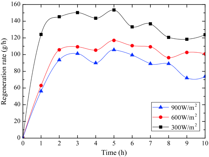
Variation of the regeneration rate of the solid desiccant modules with time


7.7 Analysis and Discussion of the Testing Results of the Fans and PV Panel
In order to investigate the operation of the fans and the PV panel, the power was tested under the simulated solar radiation of 900, 600 and 300 W/m2, respectively, and the results are shown in Fig. 51.

Variation of the power of the fans and PV panel with time
Figure 51 indicates that the power of the fans and the PV panel was relatively stable with time under different simulated solar radiation. The average power of the PV panel under the simulated solar radiation of 900, 600 and 300 W/m2 was 39.81 W, 26.37 and 16.89 W, respectively. This meant that the PV panel could not completely drive the fans (49.82 W) under the simulated solar radiation of 300–900 W/m2. Therefore, it was necessary to introduce the auxiliary power sources, e.g. battery, or connected to the grid to run the fans.
7.8 Comparison of the Testing Results with the Results from the Semi-empirical Model
Semi-empirical model for the dehumidification process of the SPDW will be set up based on the mass balance of the desiccant module and used to compare the testing results (as in Fig. 52). Four assumptions are taken into consideration in the analysis:

Mass transfer process for the proposed solid desiccant module
-
(1)
Axial gradient of the moisture content within the desiccant module is neglected.
-
(2)
Mass equilibrium between the solid desiccant and exit air in the module is assumed.
-
(3)
Isothermal adsorption is assumed during the dehumidification process.
-
(4)
The bulk mean value of the air is assumed to simulate the mass transfer process.
For the dehumidification process, mass balance between the dehumidified air and solid desiccant at dτ is given as follows:
When the mass of the exit air equals to that of the solid desiccant, the humidity ratio of the exit air equals to that of the solid desiccant, then [32]
The humidity ratio of the solid desiccant db depends on the water content ratio of the solid desiccant mτ, as well as the thermo-physical properties of the solid adsorbent–adsorbate pair. For silica gel and water vapour as adsorbent and adsorbate, respectively, the linear relation of the humidity ratio of the solid desiccant db and water content ratio of the solid desiccant mτ can be expressed as [132]:
Substituting Eqs. (21) and (22) in Eq. (20) gives
Solving Eq. (23) with the initial condition at τ = 0, mτ = m0,
Then, Eq. (24) can be rewritten as:
Therefore, if the initial water content ratio of the solid desiccant module (m0) and water content ratio of the saturated solid desiccant module (me) were given, the water content ratio of the solid desiccant module in any time mτ can be predicted.
For the initial water content ratio of solid desiccant module m0, it was small due to the fully dried modules in the electronic oven for 12 h at 120 °C temperature. Therefore, the m0 was neglected in this study.
The water content ratio of the saturated solid desiccant module me was determined from the experiments that by putting the desiccant modules into the hygrothermostat under the five experimental conditions, respectively, until the variation of the water content ratio was less than 1%, the solid desiccant was then saturated, and the results are shown in Table 31.
Then, the water content ratio of the solid desiccant module in any time mτ could be predicted from the semi-empirical model as shown in Eq. (27), and the regression constant β could be obtained from the experimental data through nonlinear regression. The results are compared with the testing results in Fig. 53.

Comparison between the results from the testing and semi-empirical model
From Fig. 53, by comparing the testing results with the results from the semi-empirical model, the semi-empirical model performed well in predicting the water content ratio of the solid desiccant module during the experiments with the mean relative errors less than 9.58%, which may be caused from the assumption of the isothermal adsorption of the model. In addition, the semi-empirical model described the relationship between the water content ratio of the solid desiccant module and the effective dehumidification time, providing an effective and convenient way to predict the water content ratio for a certain time in the dehumidification process.
7.9 Conclusions
In this section, the solar-powered dehumidification window (SPDW) incorporating double-glazed window with the solid desiccant packed-bed and photovoltaic panel had been proposed. The solid desiccant bed was fit into the space between the inner and outer layers of the windows to achieve the compact building integration and energy-saving. In order to investigate the dehumidification and regeneration performance of the SPDW, the testing rig had been constructed and tested in the laboratory under different inlet air conditions and simulated solar radiations.
For the window operated under the inlet air temperature of 19.2 °C and relative humidity of 86.1% within the 10-hour dehumidification period, the transient moist removal reached the maximum of 7.1 g/kg and the maximum dehumidification efficiency of 58.60%. The released adsorption heat absorbed by the dehumidified air reached 89.66% that resulted in the maximum temperature difference between the inlet and outlet air of 10.7 °C corresponding to the inlet air temperature of 19.2 °C and relative humidity of 86.1%, meaning that most of the released adsorption heat was transferred to the sensible heat load of the air-conditioning system. The desiccant temperature increased from the beginning to the end with the maximum of 35.3 °C for the simulated solar radiation of 900 W/m2, leading to the regeneration rate of 153 g/h. The average power of the fans was found to be 49.82 W, while the maximum power of the PV panel was 39.83 W for the simulated solar radiation of 900 W/m2, meaning that the fans could not be completely driven by the PV panel. An agreement between the results from the testing and the semi-empirical model was achieved with the mean relative errors less than 9.58%, and the semi-empirical model was developed to predict the water content ratio of the desiccant modules in the dehumidification process.
References
Shenzhen Institute of Building Research Co., Ltd. (2016) Design of green buildings in South China and related cases. China Architecture & Building Press, Shenzhen
Zhang T, Liu X, Zhao K et al (2010) Application analysis of air conditioning system with independent temperature and humidity control. Build Sci 26(10):146–150
Zhu D, Ju F, Li X et al (2007) Research progress in dehumidifiers. Heat Vent Air Cond 04:35–40+23
Guo N (2016) Experimental study of solid dehumidification and purification systems of endogenous air. Inner Mongolia University of Science & Technology, Inner Mongolia
Liu X, Jiang Y, Zhang T (2013) Temperature and humidity independent control of air-conditioning systems, vol 2. China Architecture & Building Press, Beijing
Yeboah SK, Darkwa J (2016) A critical review of thermal enhancement of packed beds for water vapor adsorption. Renew Sustain Energy Rev 58:1500–1520
Misha S, Mat S, Ruslan MH et al (2012) Review of solid/liquid desiccant in the drying applications and its regeneration methods. Renew Sustain Energy Rev 16(7):4686–4707
Hamed AM (2003) Desorption characteristic of desiccant bed for solar dehumidification/humidification air conditioning systems. Renewable Energy 28(13):2099–2111
Yadav A, Bajpai VK (2012) Experimental comparison of various solid desiccants for regeneration by evacuated solar air collector and air dehumidification. Dry Technol 30(5):516–525
Tu R, Liu XH, Jiang Y (2014) Performance analysis of a two-stage desiccant cooling system. Appl Energy 113:1562–1574
Xue D (1997) Air conditioning. Tsinghua University Press, Beijing
Brundrett GW (1987) Handbook of dehumidification technology. Butterworths, London
Zhao L (2014) Research and optimization on performance of low-temperature adsorption desiccant material. Shandong University, Shandong
Fang Y, Jiang G (2005) Review on adsorbent materials of rotary-type dehumidifier. Chem Ind Eng Prog 24(10):1131–1135
Yu X, Wang S, Jiang W et al (2011) Synthesis and characterization of molecular sieve SAPO-5. J Jilin Inst Chem Technol 11:4–7
Liu X, Li Y, Feng C (2012) Preparation, characterization and photocatalytic activities of polyoxometalates immobilized on mesoporous molecular sieve. Spectrosc Spectr Anal 4:1020–1023
Yu C, Wei C (2011) Preparation and application of polymer mesocomposites. Mater Rev 5:60–63
Karamanis D, Vardoulakis E (2012) Application of zeolitic materials prepared from fly ash to water vapor adsorption for solar cooling. Appl Energy 97:334–339
Kubota M, Hanada T, Yabe S et al (2011) Water desorption behavior of desiccant rotor under microwave irradiation. Appl Therm Eng 31(8–9):1482–1486
Kubota M, Hanada T, Yabe S et al (2013) Regeneration characteristics of desiccant rotor with microwave and hot-air heating. Appl Therm Eng 50(2):1576–1581
Kodama A (2010) Cross-contamination test of an enthalpy wheel loading a strong acidic cation ion-exchange resin or 3A zeolite as a desiccant material. J Chem Eng Jpn 43(1):901–905
Li Y (2014) Study on dehumidification and regeneration characteristics of porous media. Inner Mongolia University of Science & Technology, Inner Mongolia
Kumar SR, Pillai PK, Warrier KGK (1998) Synthesis of high surface area silica by solvent exchange in alkoxy derived silica gels. Polyhedron 17(10):1699–1703
Chung TW, Yeh TS, Yang TCK (2001) Influence of manufacturing variables on surface properties and dynamic adsorption properties of silica gels. J Non-Cryst Solids 279(2):145–153
Guo J (2011) Study on dehumidification performance of modified silica gel/molecular sieve complex. South China University of Technology, Guangzhou
Li X (2011) Study on the dehumidification enhancement of desiccant-coated heat exchanger. Shanghai Jiao Tong University, Shanghai
Zheng Y, Yuan W, Wang H et al (2006) Experiments on dynamic dehumidification of internally cooling compact solid dehumidifier. J Beijing Univ Aeronaut Astronaut 32(9):1100–1103
Yuan W, Yi Z, Liu X et al (2008) Study of a new modified cross-cooled compact solid desiccant dehumidifier. Appl Therm Eng 28(17):2257–2266
Peng Z, Dai Y (2011) Transient dehumidification performance of a novel regenerative desiccant heat exchanger. Acta Energiae Solaris Sinica 32:530–536
Ge TS, Dai YJ, Wang RZ et al (2010) Experimental comparison and analysis on silica gel and polymer coated fin-tube heat exchangers. Energy 35(7):2893–2900
Ge TS, Dai YJ, Wang RZ (2011) Performance study of silica gel coated fin-tube heat exchanger cooling system based on a developed mathematical model. Energy Convers Manag 52(6):2329–2338
Kabeel AE (2009) Adsorption-desorption operations of multilayer desiccant packed bed for dehumidification applications. Renew Energy 34(1):255–265
Song W, Li W, Ge Y et al (2014) Experimental study on fixed bed structure for solid adsorption dehumidification. Build Energy Effic 08:21–24
Ramzy A, Abdelmeguid H, Elawady WM (2015) A novel approach for enhancing the utilization of solid desiccants in packed bed via intercooling. Appl Therm Eng 78(78):82–89
Pesaran AA, Mills AF (1987) Moisture transport in silica gel packed beds—II. Experimental study. Int J Heat Mass Transf 30(6):1051–1060
Ramzy KA, Kadoli R, Babu TPA (2014) Significance of axial heat conduction in non-isothermal adsorption process in a desiccant packed bed. Int J Therm Sci 76(2):68–81
Ramzy AK, Kadoli R, Ashok BTP (2013) Experimental and theoretical investigations on the cyclic operation of TSA cycle for air dehumidification using packed beds of silica gel particles. Energy 56(5):8–24
Mitra S, Aswin N, Dutta P (2016) Scaling analysis and numerical studies on water vapour adsorption in a columnar porous silica gel bed. Int J Heat Mass Transf 95:853–864
Ge Y, Li W, Chen L et al (2012) Experimental study on fixed bed structure for solid adsorption dehumidification. Build Sci 12:80–84
Feng S, Chen Z, Tang G et al (2001) Test and studying on honeycomb passage silica gel moisture trap. Contam Control Air-Cond Technol 01:21–24
Worek WM, Lavan Z (1982) Performance of a cross-cooled desiccant dehumidifier prototype. J SolEnergy Eng 104(3):187–196
Fathalah K, Aly SE (1996) Study of a waste heat driven modified packed desiccant bed dehumidifier. Energy Convers Manag 37(4):457–471
Zhao Y, Dai YJ, Ge TS et al (2015) On heat and moisture transfer characteristics of a desiccant dehumidification unit using fin tube heat exchanger with silica gel coating. Appl Therm Eng 91:308–317
Zhou H, Qian M, Feng J, Sun L (2010) Building materials thermal physics performance and data manual. China Construction Industry Press, Beijing
Bi Y, Yang W, Zhao X (2018) Numerical investigation of a solar/waste energy driven sorption/desorption cycle employing a novel adsorbent bed. Energy
Collins RE (1984) Flow of fluids through porous materials. Petroleum Industry Press, Beijing
Cheng W, Wei W (2007) Theoretical analysis of phase change material storage with porosity metal foams. Acta Energiae Solaris Sinica 28(7):739–744
Wang B, Wang R (1983) Thermal conductivity of moisture-containing building materials. J Eng Thermophys 4(2):146–152
Chen H, Li T, Wang L et al (2009) Sorption performance of consolidated composite sorbent used in solar-powered sorption air-conditioning system. J Chem Ind Eng Soc China
Zhao Y, Dai YJ, Ge TS et al (2016) A high-performance desiccant dehumidification unit using solid desiccant coated heat exchanger with heat recovery. Energy Build 116:583–592
Zaltash A, Petrov AY, Rizy DT et al (2006) Laboratory R&D on integrated energy systems (IES). Appl Therm Eng 26(1):28–35
Myat A, Thu K, Choon NK (2012) The experimental investigation on the performance of a low temperature waste heat-driven multi-bed desiccant dehumidifier (MBDD) and minimization of entropy generation. Appl Therm Eng 39(39):70–77
Ng KC, Myat A, Hideharu Y et al (2011) A dehumidifier and a method of dehumidification: WO, WO/2011/090438[P]
Yao Y (2012) Research progress in the application of ultrasonic technology in the regeneration of desiccants for air-conditioning. J Refrig 33(06):12–18
Yao Y, Zhang W, Liu S (2009) Feasibility study on power ultrasound for regeneration of silica gel—a potential desiccant used in air-conditioning system. Appl Energy 86(11):2394–2400
Yao Y, Liu S, Zhang W (2008) Regeneration of silica gel using high-intensity ultrasonic under low temperatures. Energy Fuels 23(1):457–463
Yao Y, Zhang W, Liu S (2009) Parametric study of high-intensity ultrasonic for silica gel regeneration. Energy Fuels 23(6):3150–3158
Zhang W, Yao Y, He B et al (2011) The energy-saving characteristic of silica gel regeneration with high-intensity ultrasound. Appl Energy 88(6):2146–2156
Yang K, Yao Y, Liu S et al (2013) Investigation on applying ultrasonic to the regeneration of a new honeycomb desiccant. Int J Therm Sci 72(10):159–171
Yao Y, Wang W, Yang K (2015) Mechanism study on the enhancement of silica gel regeneration by power ultrasound with field synergy principle and mass diffusion theory. Int J Heat Mass Transf 90:769–780
Yao Y, Zhang W, He B (2011) Investigation on the kinetic models for the regeneration of silica gel by hot air combined with power ultrasonic. Energy Convers Manag 52(11):3319–3326
Yao Y, Zhang W, Yang K et al (2012) Theoretical model on the heat and mass transfer in silica gel packed-beds during the regeneration assisted by high-intensity ultrasound. Int J Heat Mass Transf 55(23):7133–7143
Yao Y, Yang K, Zhang W et al (2014) Parametric study on silica gel regeneration by hot air combined with ultrasonic field based on a semi-theoretic model. Int J Therm Sci 84:86–103
Ma K, Jin S, Pan Y (2016) Research status and prospect of ultrasonic technology in food development. The Food Industry
Song GS, Hu S, Li L (2008) Researches and applications of ultrasonic technology in food industry. Mod Food Sci Technol 06:609–612
Yao S, Hertzog DE, Zeng S et al (2003) Porous glass electroosmotic pumps: design and experiments. J Colloid Interface Sci 268(1):143–153
Zhang G, Shao S, Lou X et al (2014) Investigation on the adsorption mechanism and electro-osmosis regeneration of common solid desiccants. J Refrig 35(1):8–13
Qi R, Tian C, Shao S (2010) Experimental investigation on possibility of electro-osmotic regeneration for solid desiccant. Appl Energy 87(7):2266–2272
Fan L (2014) Research of microwave heating in dehumidification technology and application of evaporative air conditioning. Harbin Institute of Technology, Harbin
Saitake M, Kubota M, Watanabe F et al (2007) Enhancement of water desorption from zeolite by microwave irradiation. Kagaku Kogaku Ronbunshu 33(1):53–58
Watanabe F, Sumitani K, Kashiwagi T et al (2009) Influence of microwave irradiation on water-vapor desorption from zeolites. Kagaku Kogaku Ronbunshu 35(5):431–435
Liu H, Ma X, Guo P et al (2014) Microwave drying characteristics and kinetic model of food waste. Chin Sci Bull 59(10):936–942
Ohgushi T, Ishimaru K (2001) Dielectric properties of dehydrated NaA zeolite, analyses and calculation of dielectric spectra. Phys Chem Chem Phys 3(15):3229–3234
Ohgushi T, Akiko W (2001) Simple suppressing method of thermal runaway in microwave heating of zeolite and its application. PhysChemcomm 4(3):18–20
Ohgushi T, Nagae M (2003) Quick activation of optimized zeolites with microwave heating and utilization of zeolites for reusable desiccant. J Porous Mater 10(2):139–143
Ohgushi T, Nagae M (2005) Durability of zeolite against repeated activation treatments with microwave heating. J Porous Mater 12(4):265–271
Hu J (1999) Study on the production technology of microwave rapid drying silica gel. Packag Eng
Fairey P, Vieira R, Kerestecioglu A (1985) Desiccant enhanced nocturnal radiation: a new passive cooling concept. In: Proceedings of the 10th national passive solar conference, Raleigh, NC, pp 271–275
Fairey P, Kerestecioglu A, Vieira R Analytical investigation of the desiccant enhanced nocturnal radiation cooling concept. In: Florida Solar Energy Center, FSEC-CR-152-86, Cape Canaveral, FL, 1986
Swami M, Rudd A, Fairey P et al An assessment of the desiccant enhanced radiative (DESRAD) cooling concept and a description of the diurnal test facility. In: Florida Solar Energy Center, FSEC-CR-237-88, Cape Canaveral, FL, 1989
Swami M, Fairey P, Kerestecioglu A An analytical assessment of the desiccant enhanced radiative cooling concept. In: Proceedings of the 12th annual ASME solar energy conference, Miami, Florida, USA, 1990, pp 397–406
Lu SM, Shyu RJ, Yan WJ et al (1995) Development and experimental validation of two novel solar desiccant-dehumidification-regeneration systems. Energy 20(8):751–757
Saito Y (1993) Regeneration characteristics of adsorbent in the integrated desiccant/collector. J SolEnergy Eng 115(3):169–175
Techajunta S, Chirarattananon S, Exell RHB (1999) Experiments in a solar simulator on solid desiccant regeneration and air dehumidification for air conditioning in a tropical humid climate. Renew Energy 17(4):549–568
Kumar A, Chaudhary A, Yaday A (2014) The regeneration of various solid desiccants by using a parabolic dish collector and adsorption rate: an experimental investigation. Int J Green Energy 11(9):936–953
Pramuang S, Exell RHB (2007) The regeneration of silica gel desiccant by air from a solar heater with a compound parabolic concentrator. Renew Energy 32(1):173–182
Zheng Y, Yuan W (2006) Study of solar/waste heat driven solid desiccant cooling system. Refrig Air-cond
Ge TS, Dai YJ, Li Y et al (2012) Simulation investigation on solar powered desiccant coated heat exchanger cooling system. Appl Energy 93(5):532–540
Ge TS, Dai YJ, Wang RZ et al (2013) Feasible study of a self-cooled solid desiccant cooling system based on desiccant coated heat exchanger. Appl Therm Eng 58(1–2):281–290
Ge TS, Dai YJ, Wang RZ et al (2010) Experimental comparison and analysis on silica gel and polymer coated fin-tube heat exchangers. Energy 35(7):2893–2900
Zheng H, He K, Yang Y et al (2006) Study on a multi-effect’s regeneration and integral-type solar desalination unit with falling film evaporation and condensation processes. Sol Energy 80(9):1189–1198
Fountoukidis E, Yanniotis S, Leontaridis N (1993) Theoretical model for direct solar regeneration of hygroscopic solutions. Sol Energy 51(4):247–253
Yadav A (2014) The regeneration of various solid desiccants by using a parabolic dish collector and adsorption rate: an experimental investigation. Int J Green Energy 11(9):936–953
Tang Y, Zheng R, Li X (1988) Solar regeneration of desiccant for drying volatile and aromatic material. Acta Energiae Solaris Sinica 9(3):310–316
Guo H (2013) Experiment study on the properties of the solid desiccant bed regenerated with solar directly. Guangdong University of Technology, Guang Zhou
Liu X, Li Z, Jiang Y et al (2006) Annual performance of liquid desiccant based independent humidity control HVAC system. Appl Therm Eng 26(11):1198–1207
Ye Y, Zhi LU, Lian ZW et al (2008) Experimental study on the feasible application of ultrasonic in regeneration of solid dehumidizer. J Shanghai Jiaotong Univ 42(1):138–141
Rambhad KS, Walke PV, Tidke DJ (2016) Solid desiccant dehumidification and regeneration methods—a review. Renew Sustain Energy Rev 59:73–83
Jani DB, Mishra M, Sahoo PK (2016) Solid desiccant air conditioning—a state of the art review. Renew Sustain Energy Rev 60:1451–1469
Techajunta S, Chirarattananon S, Exell RHB (1999) Experiments in a solar simulator on solid desiccant regeneration and air dehumidification for air conditioning in a tropical humid climate. Renew Energy 17(4):549–568
Pramuang S, Exell RHB (2007) The regeneration of silica gel desiccant by air from a solar heater with a compound parabolic concentrator. Renew Energy 32(1):173–182
Bhool R, Kumar P, Kumar P, Mehla, A (2014) Performance evaluation and regeneration of activated charcoal by simulated solar parabolic dish collector. Int J Sci, Eng Technol Res (IJSETR) 3:1507–1514
Dong L, Dai Y, Li H et al (2011) Experimental investigation and theoretical analysis of solar heating and humidification system with desiccant rotor. Energy Build 43(5):1113–1122
Cherbański R, Molga E (2009) Intensification of desorption processes by use of microwaves—an overview of possible applications and industrial perspectives. Chem Eng Process 48(1):48–58
Bathen D (2003) Physical waves in adsorption technology—an overview. Sep Purif Technol 33(2):163–177
Zhu J, Kuznetsov AV, Sandeep KP (2007) Mathematical modeling of continuous flow microwave heating of liquids (effects of dielectric properties and design parameters). Int J Therm Sci 46(4):328–341
Ania CO, Parra JB, Menéndez JA et al (2005) Effect of microwave and conventional regeneration on the microporous and mesoporous network and on the adsorptive capacity of activated carbons. Microporous Mesoporous Mater 85(1–2):7–15
Polaert I, Estel L, Huyghe R et al (2010) Adsorbents regeneration under microwave irradiation for dehydration and volatile organic compounds gas treatment. Chem Eng J 162(3):941–948
Shi C, Wang T, Zhang FH et al (2015) Study on regeneration of granular activated carbon by microwave thermal treatment. J Sichuan Univ
Appukkuttan P, Eycken EVD (2006) Microwave-assisted natural product chemistry. In: Microwave Methods in Organic Synthesis. Springer, Berlin, Heidelberg, pp 1–47
Reimbert, CG, MINZONI AA et al (1996) Effect of radiation losses on hotspot formation and propagation in microwave heating. Ima J Appl Math 57(2):165–179
Yuen FK, Hameed BH (2009) Recent developments in the preparation and regeneration of activated carbons by microwaves. Adv Coll Interface Sci 149(1–2):19–27
Hazevazife A, Moghadam PA, Nikbakht AM et al (2012) Designing, manufacturing and evaluating microwave -hot air combination drier. Life Sci J 9(3):630–637
Yang WS, Guo HH, Wang ZY et al (2013) Performance research of a solid desiccant material regenerating directly with solar energy. New Build Mater 291–294:145–151
Mao HP, Zhang XD, Xue LI et al (2008) Model establishment for grape leaves dry-basis moisture content based on spectral signature. J Jiangsu Univ 29(5):369–372
Yang WS, Deng H, Bi Y et al (2016) Experimental study on regeneration performance of solid desiccant by micro wave. Build Technol Dev 43:11–15
Niu JL, Zhang LZ (2002) Effects of wall thickness on the heat and moisture transfers in desiccant wheels for air dehumidification and enthalpy recovery. Int Commun Heat Mass Transf 29(2):255–268
Zhang LZ, Niu JL (2002) Performance comparisons of desiccant wheels for air dehumidification and enthalpy recovery. Appl Therm Eng 22(12):1347–1367
Koua KB, Fassinou WF, Gbaha P et al (2009) Mathematical modelling of the thin layer solar drying of banana, mango and cassava. Energy 34(10):1594–1602
Ozdemir M, Devres YO (2000) The thin layer drying characteristics of hazelnuts during roasting. J Food Eng 42(4):225–233
Soysal Y (2004) Microwave drying characteristics of parsley. Biosys Eng 89(2):167–173
Ren G, Chen F (1998) Drying of American ginseng (Panax quinquefolium) roots by microwave-hot air combination. J Food Eng 35(4):433–443
Celma AR, Rojas S, Lopez-Rodríguez F (2008) Mathematical modelling of thin-layer infrared drying of wet olive husk. Chem Eng Process 47(9–10):1810–1818
Liu Y, Yan H, Lam JC (2014) Thermal comfort and building energy consumption implications—a review. Appl Energy 115(4):164–173
Pérez-Lombard L, Ortiz J, Pout C (2014) A review on buildings energy consumption information. Energy Build 40(3):394–398
Wang RZ, Yu X, Ge TS et al (2013) The present and future of residential refrigeration, power generation and energy storage. Appl Therm Eng 53(2):256–270
Mazzei P, Minichiello F, Palma D (2005) HVAC dehumidification systems for thermal comfort: a critical review. Appl Therm Eng 25(5):677–707
Chiang YC, Chen CH, Chiang YC et al (2016) Circulating inclined fluidized beds with application for desiccant dehumidification systems. Appl Energy 175:199–211
La D, Dai YJ, Li Y et al (2012) Use of regenerative evaporative cooling to improve the performance of a novel one-rotor two-stage solar desiccant dehumidification unit. Appl Therm Eng 42(4):11–17
Awad MM, Kattaya AR, Hamed AM, et al (2008) Theoretical and experimental investigation on the radial flow desiccant dehumidification bed. Appl Thermal Eng 28(1):75–85
Hamed AM, Abd-Elrahman WR, El-Emam SH et al (2013) Theoretical and experimental investigation on the transient coupled heat and mass transfer in a radial flow desiccant packed bed. Energy Convers Manag 65(6):262–271
Hamed AM, Rahman WR, An E, El-Emam SH (2010) Experimental study of the transient adsorption/desorption characteristics of silica gel particles in fluidized bed. Energy 35(6):2468–2483
Author information
Authors and Affiliations
Corresponding author
Editor information
Editors and Affiliations
Rights and permissions
Copyright information
© 2019 Springer Nature Switzerland AG
About this chapter

Cite this chapter
Yang, W., Liu, S., Zhai, X., Bi, Y., Wang, Z., Zhao, X. (2019). Solar Desiccant (Absorption/Adsorption) Cooling/Dehumidification Technologies. In: Zhao, X., Ma, X. (eds) Advanced Energy Efficiency Technologies for Solar Heating, Cooling and Power Generation . Green Energy and Technology. Springer, Cham. https://doi.org/10.1007/978-3-030-17283-1_7
Download citation
DOI: https://doi.org/10.1007/978-3-030-17283-1_7
Published:
Publisher Name: Springer, Cham
Print ISBN: 978-3-030-17282-4
Online ISBN: 978-3-030-17283-1
eBook Packages: EnergyEnergy (R0)