
Abstract
In its simplest form, the operations of a railroad can be split into two disciplines: line-of-road operations and terminal operations. Some traffic, especially that moving in unit bulk, intermodal or automotive trains, will see few terminals between origin and destination, while traffic often termed “general merchandise” may visit several terminals en-route. Management devotes the largest amount of analytic effort to line-of-road operations, and tools exist for its analysis. Unfortunately, while terminal operations, including freight car classification activities, consume roughly 2/3 of railcar time—versus 1/3 for line of road—there are few tools to analyze terminal operations. This accounts, at least in part, for the limited capital investment railroads make in improving classification facilities. Most railroads and many consulting firms have staffs dedicated to using tools to analyze line-of-road operation and justify capital improvements; few similar efforts exist for terminal operations.
Access provided by Autonomous University of Puebla. Download chapter PDF
Keywords
These keywords were added by machine and not by the authors. This process is experimental and the keywords may be updated as the learning algorithm improves.
9.1 Introduction
In its simplest form, the operations of a railroad can be split into two disciplines: line-of-road operations and terminal operations. Some traffic, especially that moving in unit bulk, intermodal or automotive trains, will see few terminals between origin and destination, while traffic often termed “general merchandise” may visit several terminals en-route. Management devotes the largest amount of analytic effort to line-of-road operations, and tools exist for its analysis. Unfortunately, while terminal operations, including freight car classification activities, consume roughly 2/3 of railcar time—versus 1/3 for line of road—there are few tools to analyze terminal operations. This accounts, at least in part, for the limited capital investment railroads make in improving classification facilities. Most railroads and many consulting firms have staffs dedicated to using tools to analyze line-of-road operation and justify capital improvements; few similar efforts exist for terminal operations.
Why the discrepancy between analytic abilities for line of road and terminal? Fundamentally, line-of-road operation, while often difficult to optimize, is conceptually straightforward—establish a feasible meet and pass plan for a given set of trains on a fixed physical plant subject to constraints imposed by maintenance of way demands, operational control methods (signaling, e.g., CTC, ABS or dark territory), hours-of-service limitations, and other factors. The analytic scope is at the train level. Compare this to the terminal problem—establish a feasible train arrival, car inspection, car classification, train assembly, train departure, car repair, locomotive servicing and crew change plan for a given set of trains and a specified blocking plan on a fixed physical plant subject to constraints imposed by maintenance of way demands, operational control methods (e.g., hand-throw or remote control turnouts, remote control locomotive operation), work rule limitations, customer demand at industries serviced by that terminal, and other factors. The analytic scope is now on multiple levels—train, block, individual car, and possibly even individual resource level. Given the complexity, it is not surprising that development of tools for terminal analysis has lagged far behind the development of similar capabilities for line-of-road operations.
Consider the line-of-road and terminal operations visually. If a road operation is described as “single track Centralized Traffic Control with sidings,” one need only know train schedules, running times and length and location of sidings to perform a basic analysis. Once a train has entered the line segment, it must follow a possibly large but well-defined sequence of moves before it exits the line segment. If, instead, a terminal facility is described as a “10 track flat classification yard,” how much of its operations can be envisaged? As before, train schedules and track lengths are important, but the tracks’ relative orientation may be the most critical. Each of the track layouts in Fig. 9.1, while matching the description, would have fundamentally different performance characteristics.

Samples of yard layouts. 10 track with mainline at the side. 10 track with mainline through the middle. 10 track with separate dedicated receiving and departure tracks. 10 track trapezoid. 10 track stub end
The analyst must also know full detail about the trains—the physical characteristics of each car and each car’s destination—as well as the terminal’s blocking plans—what function does this yard perform in support of the railroad’s network, i.e., does the yard simply support local operations or does it have a role in switching cars moving through to other terminals? What resources, such as car inspectors and yard crews, are available by shift? Do work rules permit crew members to be used flexibly, and can switching be performed by locomotives remotely controlled by a crew member on the ground who can also line switches himself? No longer are we dealing with a well-defined sequence of moves as with the line-of-road operation, so process definition becomes far more complex, and analytic tools become more scarce.
9.2 Reasons to Simulate
Yard simulation, if it can be made cost effective, can serve many functions:
-
Improve operations through training—with many yard personnel now hired off the street, it is important that basic skills and knowledge be learned before going on the job.
-
Improve operations through improved processes—railroads seek to avoid capital investment by improving their procedures within existing facilities. Perhaps new methods of operation or addition of resources such as yard crews and car inspectors can be tested through simulation and found to provide sufficient benefits so that no capital expenditure is needed.
-
Identify required capital investment—when possible, railroads will make modest investments in existing facilities. Simulation is needed to estimate the benefits derived from new or lengthened tracks, crossovers, improved car repair and locomotive servicing capabilities, and other modest investments. If large improvements in network performance are needed, larger investments will be required. In such cases, network models—not yard models—are generally used to identify the benefits that the network would experience after constructing the new facility. These models flow traffic over the railroad’s network with and without the new yard, and identify the reduced car handlings, faster and less expensive switching, fewer miles, etc. derived from the investment. However, a yard simulation will still be needed to ensure that the new facility’s performance is consistent with the performance parameters (e.g., blocks made, processing time, and costs) assumed in the network model.
-
Evaluate train schedule feasibility—a railroad is a highly dynamic system with frequent changes in traffic patterns. This necessitates adjustments in train routes and train schedules, impacting both road and terminal operations. A frequent concern is that the existing operating plan—or an alternative under consideration—may call for a rate of train arrivals and departures at a terminal that exceeds the terminal’s processing capacity. Yard simulation can then be used to determine whether the yard can process trains at a rate consistent with the desired arrival and departure schedules.
-
Provide replay capability—well-designed yards will remain fluid under a variety of traffic and operating conditions, but problems can arise that overwhelm them, causing terminal congestion. Simulation can assist in two ways: design and evaluate recovery plans and identify the factors that caused the congestion in the first place.
9.3 The Problem
Let us start with a simple yard and understand the fundamental processes.
9.3.1 Train Arrival
Terminals often have little input on when a train arrives or the order in which they arrive, as these decisions are made by line-of-road dispatchers who give primary consideration to train priorities, schedule adherence, hours-of-service restrictions, and other line-haul factors. So, terminals seldom control the when and how of train arrival, but they are obligated to find a place to park inbound trains, clear of the main if possible. The terminal specifies the track into which the train will arrive, or a set of tracks if the train is longer than any single available track. In some cases, the terminal will be the destination of the train, and the entire train will be put away in the yard, but more commonly, the train will be picking up additional cars or setting out (i.e., dropping off) only a portion of its cars, so accommodations must be made for the through portion of the train as well as the cut (i.e., contiguous group of cars) to be picked-up from or set-out to the yard tracks. In general, picking-up cars is straightforward—separate the head end of the inbound train from the rest of the train at the point where the cars are to be added to the train, pull the head end forward, back to the cars to be picked up, couple and pull ahead, then recouple to the rear of the train. Setting-out cars can be more complicated. Depending on train blocking, yard configuration and other factors, the train may pull through a track to make a set-out at the rear of the train, or it may separate the head end from the rest of the train, pull the head end beyond the yard, and shove (i.e., push) a cut into a track.
9.3.2 Handling the Inbound Crew and Power
If the train is terminating, or if power is being changed at the terminal, the inbound power and its crew must be transported to a tie-up location—the engine house and/or locker room. This activity generally receives a high priority, because prompt repositioning frees resources for the next trip and avoids additional labor costs, especially final terminal pay. However, these considerations must be balanced against the likelihood that the movement of light power will interfere with classification and train make-up activities. Consequently, repositioning of power and crews may be delayed until higher priority activities clear the necessary route.
9.3.3 Inbound Car Inspection
When a car or cut of cars is separated from a train, the brake system will engage, setting the brakes on the cars. Before they can be switched, the brakes must be released on each car individually by a mechanical department employee who must walk the length of the cut of cars, pulling a lever that dumps the air pressure and releases the brakes. This same individual, or a pair of individuals walking either side of the cars, can also inspect the cars for mechanical damage, enabling the cars to be switched to a repair facility when they are classified. Each railroad, and often each terminal on a railroad, may have a different policy on the thoroughness of the inbound inspection, with some delaying a comprehensive car inspection until cars are being assembled into a train.
9.3.4 Switch (Classify) Cars
With the inbound power and crew clear and brakes released, it is time to sort the cars. If more than one track is ready to be switched, terminal management must decide at what time and in which order to switch the tracks. Several factors may influence the decision:
-
Arrival order, e.g., First-In, First-Out.
-
Traffic priority, e.g., intermodal/automotive versus general merchandise.
-
Time to outbound train, e.g., which track has cars with the tightest connection?
-
Track characteristics, e.g., is this track needed for a subsequent inbound train because it is the longest track?
Once the decision is made to switch a specific track, a yard engine will attach to the cut of cars and begin to handle them to different tracks based on their destinations. Physically, this is accomplished by shoving the cars, uncoupling one or more cars from the leading end of the cut, and allowing it to roll by gravity (a hump yard) or by momentum (a flat yard). While the process is conceptually simple, many complicating factors must be considered:
-
If there are as many classification tracks as there are classifications to be made, then one track can be dedicated to each. However, block sizes and track lengths vary, so more than one track may be needed for large blocks.
-
If there are more classifications to be made than there are classification tracks, cars destined to some tracks will need to be rehandled. Several blocks will be assigned to a reswitch or “sluff” track which must be pulled and switched again when time and space permit.
-
Some tracks will be reserved for special functions. Cars requiring repairs will be routed to a bad order track, while cars missing movement instructions may be routed to a no-bill track.
-
To ease train make-up, blocks destined to the same train should be assigned to adjacent or near-by tracks. This is especially important in larger yards where more than one job assembles trains, and their efficiency is tied to the ability to avoid conflicts.
-
Yard layout may complicate the switching process, especially if some yard tracks are physically separated from others. This occurs, for example, when the main line runs down the middle of the yard, effectively creating two separate yards that must be coordinated. Since blocks are now spread across more than one set of tracks, only a portion of the cars can be switched directly to the appropriate track. Sluff tracks are again required, enabling cars to be held until they can be transferred to the appropriate portion of the yard. To minimize rehandling, the yardmaster will examine the consist of inbound trains, arriving them into the portion of the yard which best matches the destinations of the cars to the classifications made there.
-
Time of day may affect which block is assigned to a track. If a block will move on a train scheduled to depart much later, the block may be switched to a reswitch or sluff track for later handling. Such reassignment is even more prevalent in yards that switch directionally—e.g., build eastbound trains half the day and westbound trains the other half. Such yards may even switch block-to-track assignments while a track is occupied with cars for the former block which have not yet been pulled for train assembly.
9.3.5 Train Assembly
Conceptually, train assembly is a straightforward process—pull cuts of cars from appropriate tracks and assemble them in the proper blocking order for the departing train. Consequently, it may be surprising that train assembly is often the largest bottleneck in a yard, especially in large facilities such as hump yards. Many factors must be considered for the process is to be efficient:
-
Yard layout will dictate where and how blocks will be combined while building the train. If there is adequate headroom, the yard engine can pull from one track, and then shove to a coupling on one or more other tracks, a process known as “doubling.” Where the headroom is limited, one track may have to be pulled at a time, with the train assembled on one or more dedicated departure tracks.
-
In large yards where more than one yard engine is building trains, movements must be carefully choreographed to avoid conflicts between the engines. As noted earlier, assigning all of a train’s blocks to adjacent or near-by tracks will cut down on cross-yard moves.
-
While it is desirable to get all cars on the next outbound train, length and tonnage restrictions often necessitate that some cars be held for the following train. In such a case, getting the most critical cars onto the train is essential, and tracks may now be switched again to “cherry-pick” specific cars (i.e., pulling a cut of cars until the desired car is reached, then setting it aside for immediate processing).
-
When assembling trains, one must be cognizant of “train-makeup” rules, which restrict where cars can be placed in a train. Some rules are tied to crew safety—cars carrying hazardous materials may be no closer than X cars from the locomotives and cannot be placed next to cars carrying explosives. Other rules are associated with managing in-train forces related to grades, curves, acceleration and braking, and take the form of limiting where empty, long or heavy cars can be placed in the train. Special yard engine moves are often required to assemble the trains consistent with these rules.
-
Yards commonly have standards that specify how much before a train’s departure the assembly should begin, with 3 h being a typical rule-of-thumb. However, if several trains are scheduled to depart within hours of each other, train assembly may have to begin earlier than desired and the process staggered among the trains to ensure that all are ready for departure on time.
9.3.6 Final Train Assembly
With all the cars for the outbound train assembled on one track (or more than one track if the train is too long for one track), the final train assembly processes begin. Mechanical forces must walk the train, lacing (i.e., connecting) the air hoses, testing the brake system, and making a comprehensive inspection to ensure that all cars are in safe working order. Cars found to be defective must either be repaired in place or switched out, possibly affecting timely train departure. Once road power is coupled to the train and road crews are aboard, the train is ready for departure.
9.3.7 Train Departure
Ideally, the assembled train is ready for departure at the time best suited for road movement, facilitated by communication between yard personnel and the road dispatcher. If cars are ready before a departure slot is available and if the yard needs the track space, cars may be advanced to a nearby siding by the yard engine, then picked up when the balance of the train can depart. Otherwise, the train will be held in the departure tracks until the dispatcher authorizes road movement. These delays can be costly, cutting into hours-of-service limits, incurring initial terminal payments to the crews and impacting crew and locomotive cycles.
9.4 Matching the Analytic Approach with Study Requirements
Simulation is a data-intensive, time-consuming process that should be avoided if simpler, more expedient approaches can provide the necessary results. Many types of studies—such as those analyzing traffic flows over an entire railroad network—do not require that individual processes in a yard be fully represented. Consider that, in its simplest form, a yard can be represented as a black box, with inputs, outputs and a specified processing time. In such a scenario, a cut-off will often be used, where any car arriving in the yard x-hours or more before a train’s departure (the “cut-off” for that train) is assumed to make the outbound train. This approach mirrors current car scheduling systems, which do not account for capacity, scheduling conflicts or other important factors.
Similar approximations of yard performance are often used by line-of-road dispatching software to reflect interaction with yard operations. Since much track capacity will be consumed if a train is held on the main out of a yard because no track is available to receive it, such software assumes that a track will be made available for a subsequent train x-hours after the arrival of a train. This is obviously better than simply assuming the yard has infinite capacity to receive trains, but does not fully reflect actual yard performance.
Recognizing cut-offs’ inherent disadvantages, researchers developed other approaches that overcame several of cut-offs’ shortcomings:
-
A cut-off assumes that all traffic arriving in the yard before the cut-off for an outbound train will make the train, while none of the traffic arriving after the cut-off will make it. This is clearly not realistic—on some days, cars arriving after the cut-off will make connections, while cars arriving before the cut-off will miss. This suggests that car connections are probabilistic, not deterministic.
-
At any time, some cars in a yard become bad-ordered, lack movement instructions, are held until billing is resolved, are switched incorrectly, are scheduled to an annulled or size-restricted train, etc. These cars will remain in the yard until the physical or informational impediments to further travel are resolved. Thus, it is appropriate to introduce an upper limit on the percentage of cars that will make an outbound train irrespective of the cut-off time.
In the 1970s as part of a federally funded research effort, M. I. T. researchers developed an approach known as PMAKE analysis, which stands for the Probability that a car will MAKE a connection as a function of time. The function is piecewise linear as shown in Fig. 9.2 (the relationship can also be represented by a smooth logit curve). Unlike the cut-off, the probability increases with time to a maximum value PMAX, which represents the maximum percentage of traffic that will make its next connection. The slope of the line is specified by T50 and T90, where T50 is the necessary time for 50 % of cars to make their first available connection, and T90 is the additional time beyond T50 at which 90 % of cars connect.

PMAKE analysis
This conceptually simple but powerful approach was integrated into a number of models. The Service Planning Model, released in the late 1970s and early 1980s, was one of the most successful network analysis tools of the period (Martland, Marcus, and Raymond, “Boston & Maine Achieves Control over Railroad Performance”, INTERFACES 16:5, September-October 1986). Some analytic tools, like M. I. T.’s Intermediate Terminal Model, are founded on the PMAKE concept. To predict average yard dwell, time estimates for each yard process (i.e., inspection, switching, train assembly, etc.) are combined to form an overall PMAKE for the yard, with T50 being the sum of the mean times for each of the required processes, and T90 calculated using the standard deviations for the processing times.
One useful result of this approach is the ability to quickly estimate the reliability of trip times when a car moves through a sequence of yards. For instance, if all yards in the sequence have a PMAX of 90 %, then cars passing through 2 yards can be expected to achieve their trip plan standard 81 % of the time (0.9 × 0.9), while the reliability of a 3-yard sequence drops to 73 % (0.9 × 0.9 × 0.9).
The development of the PMAKE concept in the 1970s was driven, in part, by the failure of earlier network modeling software that had attempted a detailed simulation of line-of-road and yard operations in a comprehensive model. One such model was developed for the Association of American Railroads (AAR) by The Midwest Research Institute, and was installed at several railroads, including the Illinois Central (now part of Canadian National). Initially, yard processes—inbound and outbound inspection, picking up and setting out cars, assembling, classification and air pumping operations—were specifically modeled. Each used its own equation of the form Y = A + BX, where Y is the total time consumed for an operation, A is a constant time, B is a coefficient reflecting the time per unit of an activity, and X is the number of units of that activity. The functions also reflected the availability of yard resources, so the projected dwell time for a car in the yard was a function of both the number of jobs in the queue and the resource availability.
Unfortunately, this approach proved untenable, partly due to the computer limitations of the time, but mostly because it proved difficult to assemble data to allocate a resource’s time to a specific activity. Instead, average times for these activities were substituted, and the simulation was completed.
On a historical note, several railroads, including the Canadian National and the former Chicago, Burlington and Quincy (now part of BNSF), built yard models internally, while some others, like the Baltimore and Ohio (now part of CSX) and Saint Louis— San Francisco (now part of BNSF) used commercial models produced by organizations like the Battelle Memorial Institute. At least one vendor, General Railway Signal, also developed a yard simulation model. It is believed that none of these models survive.
9.5 Building a Yard Simulation
9.5.1 Conceptual Design
Yard operations are typically modeled using discrete-event simulation. Initially, some exogenous event occurs—a train arrives into the simulation—which requires that a decision be made—route the train to Track 1. Once the simulation software executes this decision and the train comes to a stop in Track 1, a new event—train arrival—triggers the need for a new decision—uncouple the locomotives, route them to the engine servicing area and assign Car Inspector 1 to conduct an inbound inspection of the train. This event–decision–event–decision cycle is executed repeatedly to move cars from arrival through departure.
Yard simulation, then, can be viewed conceptually as the coordination of event simulation and decision generation and execution. The software could be envisioned as two discrete components, one we will call the “simulation engine”—capturing events, requesting decisions and executing those decisions—and the other we will call the “decision engine”—determining the next course of action. In practice, the two components are seldom separated and are often intertwined, but this view can provide useful insights for understanding the process.
9.5.1.1 Simulation Engine
From this perspective, the simulation engine can be either custom, dedicated software or a general purpose simulation package, especially if the software has been supplemented with special purpose rail libraries. Key capabilities of the simulation engine include:
-
Ability to handle simultaneous operations over a large facility—many activities occur in parallel in a physically sprawling yard, requiring software that can manage large numbers of events and resources.
-
Routing capabilities—yard movements involve often complex paths, with engines and cars moving forward, and then reversing repeatedly. Some tracks are clear for through movements, while others are blocked by standing cars. The simulation software must have an inherent ability to compute feasible, ideally optimal, routes, or the user will be required to manually prescribe large routing tables to perform this function.
-
Managing conflicts—except for the simplest yards, there will be competing requests for resources, including track paths, yard engines and mechanical inspectors. The software must have the ability to resolve such conflicts. Resources can be provided to a requestor based on First-in—First-Out, relative priority or some other rule, and requestors not receiving the required resource must be delayed until the resource is available.
-
Rich graphics—nothing sells a simulation better than snazzy graphics. The ability to reproduce physical movements—engines pulling and shoving cars, cars rolling into tracks—helps the developer ensure that the model is working properly and enables him to demonstrate to others that he has captured the problem correctly.
-
Ability to compile a rich set of statistics at various levels—since yard simulation involves the movement of individual cars, statistics will be generated at this detailed level. However, statistics may be useful at a traffic type (i.e., intermodal, automotive, general merchandise), block, train, resource utilization (i.e., crews, yard jobs, bowl tracks, leads), and yard level.
-
Ability to properly handle warm-up and shut-down periods—while it is possible to pre-populate a yard at the beginning of a simulation, it is common practice to start with an empty yard and arrive and depart trains and switch cars until a “steady-state” has been achieved, typically several days into the simulation. Similarly, during the shut-down period at the end of a simulation, no more arriving trains are processed, and the simulation ends when all cars have departed. Obviously, neither period is typical and software should be capable of statistically excluding these periods from model results. Some simulation programs also enable a “warm start” where a simulation can be run until the steady state has been reached, and the model state recorded so that future simulations can start at that point, eliminating the need for simulating the warm-up period again.
-
Probability distributions—simulations can employ fixed values, like a specific run time for arriving trains to enter the receiving yard track. Such values are often averages, meaning that there is a distribution about the mean. Simulations can be made more realistic if they rely on probabilistic rather than deterministic values to represent the start time and length of an activity, the number of resources available, and other factors driving the simulation.
-
Interface with other software—much effort will be expended to define the track network, traffic data and operating plan, so the ability to import data from other systems is critical. The simulation will also generate volumes of output statistics, so interface with analytical tools is extremely useful. Integration with database engines and common management tools like spreadsheets is essential.
-
Scenario management capability—most yard studies examine a set of physical plant and/or operating plan alternatives. Software must be able to manage multiple scenarios.
-
Internal editors—data input, manipulation, editing and creation of alternatives is greatly simplified when editors are available within the simulation platform.
9.5.1.2 Decision Engine
More important than the choice of the simulation engine is the selection of a decision engine. Over the years, many different approaches have been used. One successful implementation, TRIM, developed by Canadian National and used by CN and CSX, relied entirely on human decision makers. The computer received and processed input data, pausing at each decision point for guidance from a staff of yard modelers, who then specified what actions to take. The computer then implemented the decisions and moved ahead to the next decision point. This approach produced results that could be easily understood since the process was completely transparent, but it had a number of shortcomings. These included long turn times (a study ran at three times real time, meaning one 8-hour yard shift required over 8-hour workdays to be analyzed), subjective results (only as good as the analysts running the model), large staffing requirements (eight or more personnel might be involved), and limited repeatability (too long to be repeated and too subjective to reach the same result). The software is no longer in use.
A better approach is replacing the external, human decision-making with internal, computer-based decision processes, which are often just sets of rules similar to those that the human operator might specify. Consider the decision as to which track should be used to handle an arriving train. When asked, the human operator may just specify the next available track—a simple rule that can also be coded into a computer to guide its decisions. This is the most common approach taken by yard simulation software, although the sophistication of the rules engine may vary widely among implementations.
Where are the majority of such decisions needed?
9.5.1.3 Inbound Process
-
Train arrival sequence—If more than one train is approaching the yard, in what order should they be brought into the yard? Possible factors:
-
First-In/First-Out (FIFO)
-
Trains whose crews are about to exceed their Hours of Service (typically 12 h on duty).
-
Trains whose cars are most service-sensitive or whose connections are most in jeopardy.
-
-
Train to arrival track planning—which track should receive the inbound train? Possible factors:
-
Inbound train direction.
-
Next available track.
-
Track versus train length.
-
Track that will hold entire train.
-
If no track will hold entire train, select tracks best suited for a “double” (splitting the train over two or more tracks).
-
Short trains can be added to tracks already occupied to maximize the length of the switch cut.
-
-
For split yards (e.g., yards with tracks on both sides of the main), arrive a train into the side of the yard better suited to handling the destinations in the train.
-
-
Train to arrival track routing—if several routes exist, which should be chosen? Possible factors:
-
Shortest route.
-
Fastest route—e.g., route with fewest switches to be thrown.
-
Conflict avoidance—choose a route which does not interfere with other activities.
-
9.5.1.4 Switching Process
-
Hump sequencing—which track should be humped/flat switched next? Possible factors:
-
First-In/First-Out.
-
Tracks whose cars are most service-sensitive or whose connections are most in jeopardy.
-
Tracks which, when cleared, are best suited to handle inbound trains.
-
Blocks being made—some yards block differently at different times of day, with some creating one set of blocks for half a day, and another set for the other half.
-
-
Block to track assignment—which block should be assigned to which track? How should cars that need to be reswitched/rehumped be handled? Possible factors:
-
Blocks being made.
-
Track versus block length.
-
Arrangement of pull-down leads to departure tracks.
-
Placing all blocks for an outbound train on adjacent tracks.
-
Determination of which track or tracks best serve as sluff tracks. (These tracks will be used to hold cars awaiting billing, empty car distribution orders, etc., and those which need to be rehumped/reswitched.)
-
Splitting a large block over two or more tracks—this creates an opportunity to split a large block into several smaller blocks, reducing handlings at downstream yards.
-
Changing block assignments during the day in order to create more blocks—in this scenario, one track may hold more than one block, with the cars at the pull-down end of the bowl tracks in a block departing on trains earlier than cars at the hump/flat switch end of the bowl tracks.
-
9.5.1.5 Train Assembly Process
Pull down and train assembly sequencing—which tracks should be pulled and in what order? Possible factors:
-
Block order on trains to be built (often referred to as the train’s block standing order).
-
Desired standing order of individual cars on assembled train (e.g., keep hazardous loads five cars from the locomotives).
-
Train make-up restrictions that may require blocks of loads and blocks of empties to be placed at specific locations within the assembled train.
-
Need to perform more blocking—at times, tracks may be flat-switched at the pull-down end to create more blocks.
-
Presence of high-priority cars that require special handling. For instance, an outbound train with weight or length restrictions may not be able to handle all cars scheduled to it, so additional switching may be required to ensure that high-priority cars make the train, no matter their position in the bowl tracks.
9.5.1.6 Departure Process
Choosing an outbound route, if more than one exists—which route is best? Possible factors:
-
Direction of outbound train.
-
Conflicts with other activities.
Let us examine one of these decision points in greater detail and see how a set of rules can evolve from simple to complex.
As noted above, many factors can affect the assignment of blocks to tracks in the classification bowl. This produces a wide variety of possible decision rules:
-
The simplest rule is to make no assignment at all. The simulation can simply monitor the number of blocks needed and the length of each; as long as the required track length does not exceed the actual capacity, the simulation produces feasible results. RULE = No Rule.
-
For many yards, block-to-track assignment is quite fixed, so the decision rule is simply a set of fixed assignments. RULE = Block A → Track 1, Block B → Track 2, …
-
Consider the yard layout depicted in Fig. 9.3 where all tracks are the same length. Here, there is no advantage to use of any specific track. RULE = Use next available track for the next block created.
Fig. 9.3 
All bowl tracks same length
-
The yard layout in Fig. 9.4 is similar, but the switch lead now lines up with Track 1, making it the easiest, and therefore the most desirable, to use. RULE = Use Track 1, then use next available track.
Fig. 9.4 
All bowl tracks same length, lead aligns with track 1
-
The yard layout in Fig. 9.5 is perhaps the most common in practice. Tracks are now of different lengths, so block-to-track assignment should consider their relative sizes. One rule is appropriate when all blocks can be held in at least one of the tracks: RULE = Longest block to longest track, next longest block to next longest track,… However, the situation becomes more complicated if a block must be held on more than one track. (Note that this also creates the opportunity to break up that large block into two or more smaller blocks that might enable fewer reclassifications downstream.) RULE = For blocks exceeding the length of any bowl track, select a pair or set of tracks whose combined length most closely matches the block length; for remaining blocks, longest block to longest available track, next longest block to next longest available track,… Note that more sophisticated rules can be devised to better handle this situation.
Fig. 9.5 
Bowl tracks of varying lengths
-
Large classification yards with many bowl tracks will have multiple pull-down tracks like those depicted in Fig. 9.6. In many yards, the pull-down capacity is the constraining factor for yard throughput, as it directly affects the ability to efficiently assemble trains. Block-to-track assignment has to consider the factors noted previously (e.g., block length vs. track length), but must also consider that tracks holding blocks for the same train should be reached from the same pull-down track. This enables more than one pull-down job to work the yard at the same time, permitting more than one train to be assembled simultaneously. RULE = For each outbound train, select a “side” of the bowl; Build all blocks for that train on the same “side”; For trains with one or more blocks exceeding the length of any bowl track, select a pair or set of tracks on the chosen “side” whose combined length most closely matches the block length; for remaining blocks destined to the same train, longest block to longest available track on the same “side” of the bowl, next longest block to next longest available track on the same “side” of the bowl,… Again, note that far more sophisticated rules can be devised to better handle this situation.
Fig. 9.6 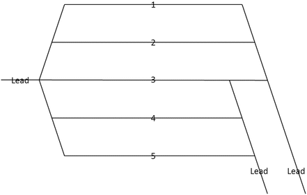
Bowl tracks of varying lengths, multiple pull down leads
-
The layouts depicted so far have focused strictly on the orientation of the classification bowl tracks, assuming the presence of dedicated receiving and departure tracks to either side of the bowl. However, many yards are situated like the layout in Fig. 9.7, where there is no distinction between receiving, bowl and departure tracks. Here, any track can be put to any use. One must now establish a comprehensive set of integrated rules to manage all decisions, from train arrival through train assembly.
Fig. 9.7 
Main line around yard, no dedicated receiving or departure tracks
-
Further exacerbating the situation are yards like that depicted in Fig. 9.8, where the mainline splits the yard into two. This significantly complicates yard operation because:
Fig. 9.8 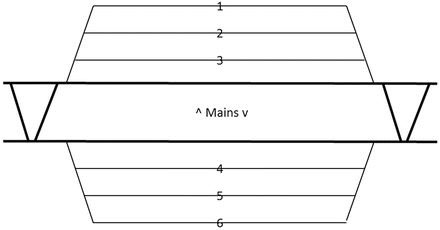
Main line splits bowl tracks
-
Not all blocks will be created on both halves of the yard, so cars for blocks not handled on a side must be rehandled on the other side. This necessitates the creation of sluff tracks on both sides to hold cars for transfer to the other side for reswitching.
-
To minimize rehandling, inbound trains can be routed into the side of the yard whose blocking plan best matches the cars’ destinations on the inbound train.
In this scenario, the rule for block-to-track assignment must be paired with the rule selecting the receiving track for an inbound train.
-


9.5.2 Data for Simulation
Yard simulations require physical plant and operational data. The former can be derived from track charts, yard diagrams, geographical information systems, and even satellite images from Google Maps and other sources. Capturing operational data once required teams of Industrial Engineers riding jobs and pouring over written records, but new technologies ease the burden. Yard management systems record the arrival and departure of trains and monitor car location throughout the yard, equipment identification systems record the passing of cars, electronic control systems for controlling switches monitor track occupancy and switch position, and cameras record much of the activity. Yard locomotives are often equipped with GPS devices, although the frequency of location logging may be inadequate for simulation purposes.
9.5.3 Other Issues to Be Resolved
Even with the software chosen, there are major decisions to be made. Among these are:
-
Physical limits of study area—consider only the yard itself, or include adjacent mainlines or other terminal facilities in the vicinity, like nearby intermodal or automotive facilities.
-
Level of detail—determined by the nature of the study.
-
Training—full detail of all phases.
-
Operational analysis—sufficient detail to understand the area of interest.
-
Physical plant analysis—sufficient detail to understand the area of interest.
-
Network modeling—can approach black box.
-
Line-of-road dispatch analysis—can approach black box.
-
-
Methods of calibration—comparison of model statistics with actual yard performance ensures that the model has captured reality well. In general, the yard’s performance in the model will be superior to its actual performance, because yard operation in the real world includes derailments, maintenance activities, inaccurate accounting, engine and car failures, staffing problems and many other disruptions to ideal operations not captured in the model. Aggregate measures have been used for calibration purposes, including average dwell time in the yard and Right Train/Right Day (cars departed on the correct train on the correct day).
-
Required level of interaction with line-of-road operations—while the focus of a study may be within a yard, movements on the adjacent main line will impact yard operations. The ability to fluidly arrive and depart trains requires that yard and line-of-road operations be coordinated. Hence, a yard simulation will have to model this interaction, at least at a basic level. To be fully robust, the model may have to include train dispatching logic to handle the routing of trains on the adjacent main lines and to and from the yard.
-
Deterministic or probabilistic—if various alternatives are to be compared, the former might be the right choice; the latter is superior when a scenario has been chosen for detailed analysis and introduction of random factors enables the robustness of the operation to be measured.
-
How to model each process—even if all processes are to be modeled in the simulation, the analyst must still decide how thoroughly the details of each process will be depicted. Consider:
-
When humping a cut of cars, will each car be individually modeled with a time processed, or will the entire cut of cars be recorded with its start time and end time only?
-
Must block-to-track assignment be modeled, or is it adequate to determine how many tracks will be needed to hold the blocks of cars and that number compared with the bowl track capacity as a whole?
-
Must activities on each track in the yard be monitored, or is it adequate to only monitor key tracks such as leads, ladders, main lines?
-
9.6 Recent Past to Current State of the Art
Before computers, yard analysis was a manual effort. Due to their complex and labor-intensive nature, such analyses were only performed when large investments were contemplated, such as the construction of a new yard. Many railroads invested heavily in new hump yards between the 1960s and the early 1980s, by which time computers had become available to assist with hump yard design, so yard models were built internally on many roads. Once the hump yard construction boom waned, models were seldom used, and few, if any, survive from that period.
At a minimum, these programs automated the data processing component of the simulations. However, they varied in the amount of internal decision-making capability each possessed.
On one extreme is the program TRIM mentioned earlier that relied entirely on interacting with human decision makers at every decision point. At the other extreme are programs whose decisions are made with comprehensive rule-based decision systems or even optimization.
At present, the author knows of several yard simulation efforts in the U.S.
Norfolk Southern Railway YardSim—beginning in 2008, Norfolk Southern embarked on the development of its YardSim software. Its research indicated that no platform or software package then existed on which to build, so it constructed its simulation program internally, relying on open source software when possible. The program includes four components:
-
Rail Yard Simulator—simulates the events and activities in the yard; its components include:
-
Simulation engine.
-
3D animation engine.
-
Process engine.
-
Statistics engine.
-
Library of business rules, heuristics, and algorithms.
-
-
Rail Yard Editor—receives yard layout data from CAD systems and converts the data to the form required by the Rail Yard Simulator.
-
Rail Yard Modeler—enables user to develop the operating policy and scheduling strategy; uses a role-based approach, where each role is modeled as an object with its responsibilities prescribed.
-
Yard Scenario Manager—enables users to specify simulation inputs and configure simulation parameters; its “what-if” capability permits manipulation of:
-
Yard layout.
-
Yard resource availability.
-
Yard operating policy and scheduling strategy.
-
Traffic volume and train plan.
-
To supplement the rules-based system, NS devised heuristics to improve decisions in three areas:
-
Hump sequencing—which cut of cars to hump next?
-
Block-to-track assignment—which tracks are best suited for a specific block or set of blocks?
-
Pull-down planning—what are the proper activities and what is the proper sequence to pull bowl tracks?
Mixed integer programming solutions were also developed in an effort to optimize the decisions in these areas.
To date, the model has examined the operations of a couple of hump yards on the NS system, and played an important role validating the design of the $100+ million expansion of Bellevue Yard in Ohio.
Innovative Scheduling (Optym) YardSim—working with CSX, Innovative Scheduling (now Optym) has constructed a web-based simulation system. The design emphasizes ease of data input (yard layout, operational data, parameters, resources by shift), realistic animation, and various output reports. A user can modify the yard layout by adding or removing tracks and analyze the impact in an integrated environment. A robust discrete-event simulation model has been adopted to ensure the portability of the model from one yard to another. The routing engine facilitating movements of locomotives and cars is independent of specific yard layout. Output reports are designed to provide easy visibility to core performance indicators as well as detailed performance reports by car, train, or specific resource as illustrated below.

Nine major hump yards, including a double hump yard, have been modeled using YardSim. The system has been validated for each yard using multiple sets of historical data, with values of primary key-performance indicators from the simulated model falling within 5 % of observed values. The system consists of 30+ decision modules and 50+ configurable parameters. This system is being used for what-if analyses of capital investment and operational case studies, and as such, is designed for use by Network Planning, Terminal Improvement Team, Service Design, Front-line managers, and Finance personnel.
AnyLogic—AnyLogic is a general purpose simulation language with the ability to perform discrete event, agent-based and system dynamics modeling. One of the features that distinguishes it from other software packages is its set of special-purpose libraries, one of which is the Rail Library, a suite of tools specifically designed to simulate railroad operations. The software inherently understands key elements of railroading—tracks, trains, cars, coupling, uncoupling, acceleration, deceleration, etc. It automatically develops routes for train movement, aligning switches as necessary. Internally, the software generates Java code, but the user’s need to write code is minimized through various constructs within the system. Logic can be developed graphically by dragging logic blocks from a template to a canvas, setting the appropriate parameters and connecting the logic blocks to describe a process. Components that model state-transitions and process charts (i.e., flow charts) convert graphical representations of logic to code.
The author constructed a simple working model for the switching activities at a small flat yard, and has worked with a consulting firm that developed and commercially deployed both a comprehensive yard model and a basic line-of-road dispatching model using AnyLogic. With the application of other special-purpose libraries—the Road and Traffic Library and the Pedestrian Library—AnyLogic can perform detailed simulations of large, multi-purpose rail yards, modeling, for instance, the train, crane, truck and crew movements within a major rail intermodal hub. Given these capabilities, AnyLogic has been acquired by four North American railroads to support their simulation efforts.
With its ability to construct agent-based models, AnyLogic may even enable development of new yard modeling paradigms. Instead of a strict discrete-event approach, what if resources were treated as agents that interacted with events seamlessly? For instance, a mechanical inspector could be an agent looking for work to be done, instead of waiting for the discrete-event engine to call him. Such an integration of simulation approaches may provide new insights.
The success of yard simulation at one road has inspired the development of more advanced software for yard simulation and management, and coordinates with line of road operation. The road is working on a mixed integer programming solution to the “yard problem,” finding that set of feasible decisions that maximizes an objective function reflecting efficiency, service quality, and cost.
9.7 Future Directions
One of the most exciting possibilities for yard simulation is developing real-time or near-real-time capabilities. Imagine providing yard management and service planners with a tool to play out a current scenario or to replay a recent scenario to see how different decisions would have improved the outcome. Such a tool may simply play out a set of manually specified decisions, might rely on optimizing software to provide superior solutions, or might use a mix of human- and computer-derived decision rules.
Today’s yard managers rely on a written or verbal turnover report at shift change to inform the incoming staff of the current status of the yard. What if that report took the form of a visual depiction of the yard’s status? The system would convey the necessary turnover information, while providing a platform for additional capabilities. The underlying database would contain real-time information on cars, blocks, tracks, trains, yard jobs, mechanical forces, etc., which could be queried to provide insights into the yard’s health. Results of the queries could be displayed graphically, highlighting, for instance, all cars in the yard containing hazardous materials or destined to a specific outbound train. Figure 9.9 shows what such a capability might look like.

Visualization of yard inventory and status
With that platform, one could easily create the ability to “see into the near future.” Simulation software would take in the current yard status, schedule known events (e.g., train arrivals, train departures) for a specified planning horizon and use an established set of rules and known resource levels to predict what the yard would look like in 1, 2, 3 or more hours into the shift. If the simulations forecast that yard conditions will worsen, alternative decisions could be tested. If a scenario can be turned quickly, it would be possible to introduce probabilistic distributions for train arrival times, process durations, and other factors so that the robustness of the solution can be ascertained.
A modest extension of this platform is the ability to replay the activities and decisions of a previous period. Many yards perform poorly at least part of the time, so yard management and service planners need to be able to examine how the yards got into trouble and identify changes that can ameliorate or prevent future problems. Once the user chooses a specific start time for the simulation and builds the initial conditions in the yard, the simulation plays out known events like train arrivals while enabling the user to specify the decision rules, resource levels, process rates, and other variables that affect yard performance. If a set of variables enables the yard’s collapse to be avoided, they can be used to specify best practice. Testing a wide variety of conditions—seasonal peaks, service disruptions, etc.—enables one to develop a set of procedures to respond quickly to those conditions before yard performance worsens.
Ideally, the planning horizon can be extended beyond a few hours to one or more days out. Unfortunately, this is not currently feasible. Car scheduling systems which provide forecasts of train consists are not capacity-constrained, so trains of unreasonable lengths can be scheduled into the future. Yards with a large amount of traffic received from another railroad or released by local industry do not know what traffic will be received or released a day from now. Until superior forecasting abilities become available, the planning horizon for real-time yard simulation will be limited to one or two shifts.
Author information
Authors and Affiliations
Corresponding author
Editor information
Editors and Affiliations
Rights and permissions
Copyright information
© 2015 Springer Science+Business Media New York
About this chapter
Cite this chapter
Baugher, R.W. (2015). Simulation of Yard and Terminal Operations. In: Patty, B. (eds) Handbook of Operations Research Applications at Railroads. International Series in Operations Research & Management Science, vol 222. Springer, Boston, MA. https://doi.org/10.1007/978-1-4899-7571-3_9
Download citation
DOI: https://doi.org/10.1007/978-1-4899-7571-3_9
Publisher Name: Springer, Boston, MA
Print ISBN: 978-1-4899-7570-6
Online ISBN: 978-1-4899-7571-3
eBook Packages: Business and EconomicsBusiness and Management (R0)