
Abstract
Feature-based engineering technology enables the current advanced engineering software tools for product and process informatics modeling. However, feature definitions are mostly recognized and limited to individual applications. The authors proposed information integration infrastructure to support multi-stage applications throughout the product lifecycle which is referred to as unified feature modeling scheme. This scheme is centered with a core model representation of a basic feature type, generic feature. This work introduces generic feature class definition, data structure, constraints, and supporting mechanisms.
Access provided by Autonomous University of Puebla. Download chapter PDF
Keywords
These keywords were added by machine and not by the authors. This process is experimental and the keywords may be updated as the learning algorithm improves.
1 Introduction
To achieve information integration among CAx applications, a shared common product model is crucial. Such a multi-view product engineering model should support different disciplinary views for various applications. Here, the term view refers to the context-dependent and self-contained interpretation data set (subset) of the entire product model (EPM) related to one particular engineering domain or aspect of the product.
In this chapter, a four-layer information integration infrastructure is presented based on Tang’s work [28] for building the shared product model. Tang’s product feature model is built on the Standard for the Exchange of Product model data (STEP) framework [23], because STEP is the international standard and has been widely accepted by both vendors and users. However, using only STEP-based product specification cannot ensure feature model integration, because STEP does not define interrelationships and constraints between applications. In this product model, the STEP framework is extended with a new concept, the unified feature model [4], under which a generic feature representation schema is given. Next, design and manufacturing feature models are described based on the new concept. The different definitions of slot features in both applications are analyzed as examples. For feature-based modeling processes, the concept of operation is introduced, followed by its representation schema. Finally, the cellular geometric model, shared by different applications, is described.
As reviewed in “A Review of Data Representation of Product and Process Models”, most of the current software tools for product development are already feature based, but are limited to individual applications. In the authors’ previous work [28], the proposed information integration infrastructure supports multi-stage applications throughout the product lifecycle, owing to the adoption of a unified feature modeling scheme [4]. This infrastructure is centered with a core model representation of a basic feature type, generic feature, which is defined based on the associative feature constraint management method.
The definition of generic feature was first introduced in Chen et al.’s work [5], which used unified modeling language (UML) and in which it was dubbed a “unified feature.” The authors felt it necessary to reconsider the name convention for the related feature terminology. As shown in Fig. 1, the authors decided to give a clear definition of generic feature, which is supposed to be the smallest grain element in the so-called feature-based informatics domain. In fact, the only change that has been made from the original publication is that the name “unified feature” has been changed to generic feature. The reason for this renaming is to maintain the consistency of conceptual understanding about the proposed feature-based theoretical informatics model. Generic feature is defined as the most basic feature entity template, or a common class as defined in an object-oriented software engineering approach; that is, the ultimate bottom-level engineering characterization data structure. Generic feature is expected to reflect the reusability and abstracting capability of the engineering semantic patterns for different engineering applications. The term unified feature is reserved to refer to the systematic framework that has been developed for implementing application systems based on the generic feature definition.

Generic feature model enhanced from Chen et al. [5]
As shown in Fig. 1, generic feature consists of four main fields: Attributes, parameters, constraints, and topological entity pointers. Attributes here refer to the properties of the feature that do not specify a feature’s shape, dimension, orientation, or position, but rather such attributes as material and surface finish (which are self-describing attributes), and non-geometric entities such as functions, rules, and machining operations (which are association attributes). On the other hand, parameters are the key to describing the shape, dimensions, orientation, and position of entities. Topological entities are those that can be shown to the user on the screen, such as a point, line, cylinder, or cube.
The major fields and methods defined in the generic feature class are described in Table 1 below with reference to Ma et al.’s recent work [13]. Again, note that there has been a name change, such that the common generic class definition, abstracted from different features, has been renamed from the original unified feature to generic feature.
2 Generic Feature Model
Theoretically, the unified feature model allows different applications to define specific features in a unified approach. Application features are modeled as the child class of the generic feature. In other words, unified feature modeling allows for the coexistence of specific views for different applications. However, although from an application point of view it is essential that each feature type has a well-defined meaning, or semantics, as a base class, a generic feature definition that enables common mechanisms, such as data storage, searching, validation, updating, and information sharing, must be modeled and developed. For more details about the class definition and properties of generic features, see Ma et al. [12].
The generic feature class includes the structured description of all common properties and methods of application feature types. Such properties include feature shape representation with parameters, constraint types, reference mechanisms, and validity methods. For example, all types of constraints are used for capturing design intent in the context of product design models. The generic feature representation schema in EXPRESS-G for database design and implementation can also be found in the literature [12]. The generic feature model provides a template for application-specific feature definition.
2.1 Feature Shape Representation
Representing the shape of a feature means defining feature geometry, topology, and their associated entities, such as Attributes, parameters, and feature manipulation (e.g., creation, modification, and deletion) functions. Feature parameters support user interfaces to create and modify features in modeling operations. To explicitly maintain the shape of a feature in a part model, shape representation in the research discussed here is based on the cellular topology of ACIS, which is on the top of the common B-rep model. For example, a block feature may have four parameters: length, width, height, and position point (see Fig. 2). Creation of a block feature is associated with the function api_solid_block(), which creates a primitive solid block with two positions. With these four parameters and feature creation schema, the shape of the block feature can be determined. Note that the length parameter is along the x-axis; the width parameter is along the y-axis; and height is along the z-axis. Other primitive features with parameters, such as cone, cylinder, wedge, and sphere, are shown in Fig. 3.

Block feature

Other primitive features with parameters
Table 2 lists other types of features with their basic parameters. Note that in the authors’ opinion, datum entities (which include datum plane, datum axis, and datum point) are also regarded as a kind of feature.
2.2 Validity Condition (Constraint) Definition
Validity conditions, namely constraints, must be explicitly defined in the unified feature model to specify relationships among features and geometric or topological entities, and provide invariant characteristics in the model.
Constraints may have various types. Some classifications, such as Dohmen’s [7] and Bettig and Shah’s [2], are reviewed below. In this work, we follow the classification by Dohmen (which is also used in most current CAD systems). Constraints can be classified as geometric constraints, dimension constraints, algebraic constraints, or semantic constraints, a constraint schema defined by Ma et al. [12].
Geometric constraints specify the geometric relations between feature elements; they can be classified into two categories, dimensional and semantic. Dimensional constraints specify distances between two feature member entities. Semantic constraints specify the topological properties of feature elements. For a vertex, edge, or face, a semantic constraint specifies the extent to which the element must lie on the product boundary. For a volume, a semantic constraint specifies the extent to which the volume is allowed to be intersected by other feature volumes instantiated later [7]. For example, a through_hole feature has semantic constraints in that the cylindrical side face must at least be partly on the material boundary, and the top and bottom faces of the cylinder must not be on the material boundary. If in the later design stage, a boss, which is a solid with material, is placed just over the hole, the semantic constraint on the top face is violated, and the through_hole feature is no longer valid. It becomes a new blind_hole feature. If both the top and bottom of the cylinder space are blocked with other material features, the feature then is transformed into a hollow_space with no accessibility to the open space.
In the generic feature definition , constraints are modeled as Attributes attached to topological entities or sub-features with the associative validation methods defined in the feature definition. Although different types of constraints have different attributes, some attributes are common:
-
Constraint_ID is the identifier of a constraint instance.
-
Constraint_name specifies the name of a constraint instance.
-
Owner_ID uniquely identifies which feature a constraint belongs to.
-
Constraint_expression represents the relationship between the constrained elements and referenced elements.
-
Constrained_entity_ID is used to specify a list of pointers of the constrained entities.
-
Referenced_entity_IDlist can be used to uniquely identify referenced entities. In modern CAD systems, the reference_entity, which is the existing geometry (a face, edge, or vertex), is regarded as a kind of datum for positioning (or orienting) a new feature.
-
Constraint_strength has an enumeration data type, which may include several levels, such as required, strong, medium, or weak. It represents the extent to which the constraint needs to be imposed when constraints conflict with one another.
-
Constraint_sense is used to specify the direction between constrained entities and referenced entities.
-
Constraint solving functions are responsible for solving constraints according to constraint types.
-
Other manipulation functions may include attribute access functions, behavior control functions, and so on.
The definition of constraint_strength is for handling over-constrained situations. Such constraint attributes were used in another external constraint solver, SkyBlue, to solve the over-constraint problem [21, 22]. The use of constraint_strength is supported by this solver. SkyBlue constraints each have an associated priority, or strength, indicating how important it is to satisfy the constraint. A constraint of lower priority is said to be weaker than a constraint of higher priority, which is called stronger. The highest strength is “required;” the lowest is “weak.” An arbitrary number of strength levels may be defined. If the SkyBlue constraint graph has conflicting constraints, SkyBlue will always determine a solution such that no unsatisfied constraint can be satisfied by making a weaker constraint unsatisfied. An example is shown in Fig. 4. Note that in the figure, a box represents a constraint, and a circle represents a variable or parameter. In the first graph, the strong constraint C2 has just been added. The second graph shows a possible chain of constraints without conflicts; in order to satisfy C2, weak constraint C1 is left unsatisfied. Another solution would be to leave C4 unsatisfied instead of C1. Since C1 and C4 have equal strength, SkyBlue will arbitrarily choose one of these solutions. The third graph shows the solution that results when the strength of the constraint has been set to medium. Here, C4 is left unsatisfied. For details of constraint solving in SkyBlue, please refer to Sannella [21, 22].

Constraint_strength for constraint solving
The constraint_sense attribute can be assigned with two string options, directed and undirected. A constraint is directed if any of the members of the constrained entities is constrained with respect to a sequence of evaluation, where those referenced entities must exist and be evaluated first. A constraint is undirected if there is no required sequence of evaluation among referenced entities, and the constraint is mutually applicable among member-constrained entities. Stated differently, in the undirected constraint, there is no difference between constrained entities and referenced entities [12].
2.3 Other Generic Feature Properties
Other properties defined in the generic feature schema can be defined as follows:
-
General feature Attributes. General feature attributes such as feature_name and feature_id are defined to serve as the index for searching during feature modeling operations.
-
Feature type. Feature type is essentially determined by the instance feature class name derived from a generic feature class, e.g., block feature or slot feature.
-
Depended_feature_id list. To maintain feature relationships, feature dependency relations should be kept during the modeling procedure [26]. The feature dependency relation is described by Bidarra et al. [3]: “feature f1 directly depends on feature f2 whenever f1 is attached, positioned or, in some other way, constrained relative to f2.” The feature dependency graph illustrates the feature dependency relations with a simplified constraint graph. In the graph, each of the edges of the graph is directed. The direction of each edge in the feature dependency graph runs from one feature to another feature that depends on it. For example, the part in Fig. 5 can be expressed as both a constraint graph and feature dependency graph as shown in Fig. 6. In these graphs, the slot and two holes are depended_feature of the base block feature. Depended_feature_id records the feature dependency relation. It plays an important role in maintaining the feature dependency graph, as well as in maintaining feature relationships during feature modeling operations. Modern CAD systems also retain feature dependency relations. For example, in Siemens NX 7.0, users can query all such information.
Fig. 5 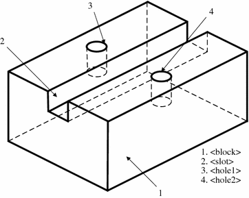
A simple example part
Fig. 6 
Constraint graph and feature dependency graph of sample part (a) Constraint graph, (b) Feature dependency graph
-
Feature label is an entity_list in the feature definition, used to record feature elements. Feature labels are attached as attributes to feature member entities, e.g., faces, edges, and vertices.
-
Domain specification. As the proposed feature model must support collaborative feature-based modeling among multiple applications [30], domain is used to designate which application a feature belongs to. Domain has the enumeration data type; values can be “design,” “manufacturing,” “assembly,” and others. By specifying different domains, multiple application features that refer to the same product geometry can coexist in the feature-oriented database.
-
Nature. The nature feature is the enumeration data type, which is either additive or subtractive. Additive means that the feature is to be instantiated by adding material. Subtractive means that the feature must be obtained by subtracting material.


2.4 Member Functions
-
Attributesaccess functions need to be defined to manage a feature’s attributes. Most of these functions are common to all types of features, e.g., backup(), findOwner(), findConstraint(), getParameter(), setParameter(), and so on. Other specific attribute methods for individual application features will be addressed at the application level.
-
Modeling operation functions. These functions are used to control the behavior of a feature during a modeling operation, e.g., creating, editing, deleting, splitting owners, merging owners, or translation.
-
Feature validation functions. Whenever a feature operation is activated via the user interface, the product model needs to be modified and updated. This process requires feature evaluation, which ensures the consistency of the geometrical model at low levels. In the work discussed here, the run-time product model is generated via an integrated solid modeler and managed based on the database records. All feature evaluation functions triggered by such operations call the solid modeler’s APIs to access and determine the geometrical procedures; they are implemented separately in the feature classes. In this way, the details of geometrical operations are maintained by the solid modeler; hence, the development effort is significantly reduced. Theoretically, feature process functions can be classified into two kinds, those dealing with the geometry and those managing constraints. With the incorporation of a solid modeler, feature process functions rely on the solid modeler for manipulating and validating feature geometry. Constraint solving functions need to call on specific algorithms defined in the individual constraint sub-classes to solve different associative relations according to their types.
-
Save and restore function. For repository purposes, feature saving and restoring functions, which are the interactions between the run-time feature model and the database, must be defined in the unified feature model classes, because these functions have to organize information for different application views according to users’ requirements.
3 Advanced Feature-Based Engineering Modeling: A Prospect of Advanced Design and Manufacturing Methodology
It is expected by the authors that with the generic feature implementation and the related database schemas [14, 16], the implementation methods of different feature-based engineering applications can be unified and developed within a systematic framework. A holistic feature-based engineering informatics modeling scheme that is based on the generic feature concept presents a complete product and process information repository, and supports high-level feature information integration across different engineering application software tools; this is dubbed unified feature modeling. This approach is to be introduced in “Unified Feature Paradigm”. The authors suggest a unified information infrastructure model that has been published by Tang et al. [29] with reference to Zha and Du’s work [31]. To briefly introduce the concept, a partial schema-level EPM representation is defined as shown in Fig. 7. A design feature model and a manufacturing feature model are represented as sub-models in the application layer; they need to be integrated with application-specific functional modules. The commonly shared feature information model below the application modules contains all components defined with a unified feature modeling scheme supporting the entire product model (EPM) with generic features as the basic semantic building units. The EPM describes information across applications, and contains the domain classification ontology and metadata. This layer contains assembly-part models, product geometry and topology, the related attributes, and so on. This chapter is dedicated to presenting the fundamentals of the generic feature concept.

Partial schema-level EPM (enhanced from Tang [28])
All EXPRESS-G representations in this work follow a convention defined by the ISO standard [9], as shown in Fig. 8. Note that in this work, those entities shown in EXPRESS-G diagrams with page reference “#, #” have been defined in the standard.

Symbol convention of EXPRESS-G [9]
In this chapter, we focus only on the feature-based design and manufacturing models of a product, which includes geometry, constraints, parameters, and dimensions. Other related information, such as product-related documents and categories, are not discussed here. In the following section, design and manufacturing feature models are described.
4 Application-Specific Feature Models
Much research effort has been directed toward feature classification. Shah and Rogers have classified features according to three basic forms: form features, precision features, and material features [25]. They considered that features can represent other logical information sets, such as assembly relations and functional entities. Rossignac clarified the distinction between intentional features and their geometric embodiment, and between volume features and surface features [20]. Juri further classified the form features into primary and secondary, and also into external and internal. Primary features correspond to cylindrical and conical shafts, whereas the secondary are holes, threads, fillets, and so on [10]. In this work, we consider only design and manufacturing features. The design feature classification used here is similar to those in commercial CAD systems (such as Pro-E, NX, and others). The classification of manufacturing features is based on the AP 224 of STEP.
4.1 Design Feature Representation
4.1.1 Design Feature Representation Schema
In this section, design features are used as an example subgroup to illustrate how application-specific feature models can be defined. A design feature model can be expressed as shown in Fig. 9.

Design feature representation schema
The primitive feature type is separated into two subtypes, additive and subtractive features. Additive features include all instances of features formed by adding material, such as cylinder, taper, sphere, boss, block, torus, and so on. Subtractive feature types represent all features such as hole, pocket, and slot that are formed by subtracting material. The transition feature type includes chamfer, edge_round, and fillet, which are always associated with other primitive features. The compound feature type is a union of several primitive features. Datum, which is used as the reference for feature-based modeling, is also regarded as a kind of design feature in the authors’ opinion. Datum has three subtypes, namely datum plane, datum axis, and datum point. Additional feature types such as extrusion, revolution, sweep, and others are also accommodated in this schema. Each specific design feature type has predefined explicit geometry, topology, parameterization, and constraints specifications. Note that not all the feature types are included in this schema, because the number of feature types is infinite [24]. But by using the generic feature model, feature definitions are extensible.
4.1.2 Example of a Design Feature Definition: Slot
Based on the generic feature definition , design features such as slot can be defined in EXPRESS-G according to STEP AP 224 [9], as shown by Ma et al. [12]. The Slot feature class inherits all the common properties and methods from the generic feature class.
4.1.2.1 Generic Shape Representation of Slot Feature
The shape of the slot feature is expressed as swept depression volume with a cross-section profile and a continuous curve of travel. The member elements associated with a slot feature are listed below:
-
Course_of_travel. This member entity specifies a 3D space curve (e.g., line and circle), that when combined with a “profile,” creates the shape of the slot. The course_of_travel can be represented as a path in EXPRESS-G. A path shall be defined as the geometrical entity pointer, which serves as the input parameter for the slot feature creation function.
-
End_conditions. End_conditions specifies the type of implicit shape at the ends of the slot, which can be blind_slot_end_type or open_slot_end_type [28]. Different slot end types require different parameters. These parameters are associated with the create_slot_end function that will be called in the slot feature creation function.
-
Sweep_shape. The sweep_shape defines the sectional 2D sweeping profile. When combined with the course of travel, the sweep operation creates the shape of a slot. For the slot feature, the sweep_shape is represented as an open_profile that could be square_u_profile, rounded_u_profile, linear_profile, vee_profile, partial_circular_profile, or tee_profile. Each type of 2D profile has its own initializing parameters. For example, square_U_profile has two parameters, length and height, which will be used in create_profile() functions to create the 2D profile. This 2D profile will be defined as an entity pointer and will serve as an input parameter for the slot feature creation function.
4.1.2.2 Constraints
In the slot feature definition, constraints are regarded as an attribute list attached to the slot feature, and are therefore defined as an attribute list. Different types of constraints (e.g., distance and angle constraints) are defined first. All the constraints are treated as common attributes in the feature’s attribute list and, to maintain feature validity, are accessible for the validity check.
4.1.2.3 Other Feature Properties
-
feature name: slot,
-
depended_feature_id: entity_list,
-
domain: “design,”
-
nature: “negative.”
Given the slot feature definition described above, instantiating a design feature slot shall be carried out in two steps: defining the shape of the slot and positioning the slot feature. Using the through_slot feature with square_U_profile and a straight line path shown in Fig. 10 as an example, the details are shown as follows:

An open-ended slot design feature with the square_U_profile
-
(a)
Specify the type of the slot feature. This is to define the sweep shape (such as square_U_profile, T_profile, or round_U_profile) of the slot feature by specifying the required parameters. In the instantiation function of slot feature, a square_U_profile entity is then parametrically created.
-
(b)
Specify the slot end type. A slot feature may have a number of end types. The shape of the slot end will be created and combined with the main body of the slot feature to complete the shape of the slot. A slot end type with parameters will be recorded as the entity pointer. In the example cited here, for open_slot_end_type, no action will be taken for the creation of the slot end shape.
-
(c)
Define a course of travel for the slot feature: it can be a line, a circle, or a 3D space curve. By default, a straight line perpendicular to the sweeping profile will be taken as the course of travel. This course of travel will be stored as an entity pointer. Here, a course of travel with direction (0, −1, 0) is created by specifying the start and end face of the slot.
-
(d)
Create the body of the slot feature by sweeping the profile along the path. This kind of operation will result in a solid as the main body of the slot feature. In this example, the given square_U_profile is swept along the direction (0, −1, 0) for a distance equal to the distance between start face and end face of the slot. The result is shown in Fig. 10.
-
(e)
Position the slot feature. To position the slot feature on a planar surface, dimension constraints, which are used to define constrained_entity (the geometry of feature to be created) and referenced_entity (existing geometry on the model), are used. In this case, for the definition of through_slot feature, two coplanar constraints (C1 and C2) are defined to determine the start and end of the slot feature. There is thus no need to set such a constraint along the y-axis. In addition, a distance constraint, D, is used to dimension the distance between the slot_left face (constrained_entity) and block_left face (reference_entity or datum).
-
(f)
Generate the 3D cell to the shape of the feature on the basis of cellular topology, and insert the shape into the part by carrying out a non-regular Boolean operation. Details for cellular topology will be described later in this chapter. Here, the slot shape will be Boolean union with the base_block and will result in the final part shown in Fig. 10.
The slot feature instance, in the example, can therefore be expressed as shown in Fig. 11. Note that upon cellular decomposition, there are two cells (3D cells) in the cellular model of the part shown in Fig. 10. The shaded cell represents a cell of slot shape, while the remainder represents the cell of the base_block.

Slot, a sub-class of design geometry feature
4.2 Manufacturing Feature Representation
4.2.1 Manufacturing Feature Representation Schema
A manufacturing feature represents a geometric shape that is associated with a manufacturing process to produce the associated part faces as designed. STEP AP 224 [9] has categorized manufacturing features into three groups: machining features, replicate features, and transition features.
A machining feature is a subtype of manufacturing feature that is formed by removing solid materials from the initial stock in order to obtain the target part geometry. According to STEP, machining features can have the following subtypes: knurl, multi_axis_feature, thread, marking, spherical_cap, outer_round, revolved_feature, and compound_feature. For details of the definition of the above-mentioned feature types, please refer to the standard [9].
Each machining feature requires direction and position to place it on a part. Therefore, a placement data structure is defined. Placement specifies the position and orientation of a machining feature relative to the base shape of a part. The data associated with a machining feature also includes the attribute usage_name. The usage_name specifies a user-defined name that contains additional information about the use of a feature. The usage_name is optional; it does not need to be specified for every machining feature.
A compound_feature unites one or more machining feature objects to create a more complex feature definition. The placement of a compound_feature is relative to the part, another compound_feature, or a replicate_feature which uses a compound_feature as the base feature. Features that are elements of the compound_feature have their placement defined relative to the compound_feature placement.
A multi_axis_feature usually identifies milling features for a part, such as boss, general_removal_volume, hole, rounded_end, planar_face, pocket, profile_feature, protrusion, rib_top, slot, and step.
In the authors’ view, manufacturing features, unlike design features, depend on the process plan, although manufacturing features can have predefined geometry. This means the geometry of a manufacturing feature can be determined only after a manufacturing operation has been determined by the process planner. In order to generate a manufacturing feature model from the part model, a predefined generic feature template library can be used for feature recognition. This procedure can be implemented automatically or interactively, or as a combination of the two. After feature recognition) and selection of appropriate machining operations, the shape of the manufacturing feature can be determined. Each manufacturing feature has an associated machining_operation, defined and stored as the attributes of the relevant geometrical entities. Candidate machining operations are those combinations of the machine tool and the cutting tool whose capabilities (shape, size, tolerance, surface finish) and accessibility satisfy the required manufacturing specifications. Therefore, the machining operation schema has four major components: machining method, machine tool, cutting tool, and machining operation.
The shape of a machining feature contains two volumes: an accessing volume and a removal volume [19]. In a traditional machining operation, material is removed by a moving cutting tool, which is attached to the machine tool. The moving cutting tool together with its chuck, which is driven by the machine tool, will sweep a volume in space. The cutting portion of this swept volume is known as the removal volume, i.e., the effective removal volume. The remainder of the swept volume is referred to as the accessing volume.
4.2.2 Example of a Machining Feature Definition: Slot
A machining feature slot can be represented in schema format as shown in Fig. 12.

Machining feature slot definition in EXPRESS-G (adopted from Ma et al. [12])
4.2.2.1 Generic Shape of the Machining Feature Slot
The machining feature slot can be used to achieve many kinds of design features. When a design feature is achieved by applying a slot manufacturing feature, they become associated; note, however, that they are neither identical nor overlapping. There are two key differences between design features and manufacturing features. The first is that in the manufacturing domain, accessing volumes and raw work piece volume should also be considered for manufacturability analysis. These volumes are evaluated when a machining operation is decided upon. The other difference is the associated relationship between the removal volume and the design feature. The design feature represents the design requirements, while the removal volume represents machining steps. The removal volumes of a machining feature are the chunks of material must be machined away with each machining steps in order to achieve the ideal design features. Unfortunately, machining features and design features are not corresponded in a one-to-one manner; rather, they are associated by the critical faces which are defined by the both types of features. Design features specify the resulting requirement about critical faces while machining features define the steps, or how those critical faces are produced.
4.2.2.2 Validity Condition Definition
-
The surface type of the slot feature must match the surface type of at least one machining operation in a given manufacturing environment.
-
Tolerance and surface finish specifications of the slot feature surface must match the tolerance/surface finish capability of at least one set of machining operations in a given manufacturing environment. It should be noted that a feature machining process is usually an ordered set of machining operations, whose total effects are equal to or better than the tolerance/surface finish specifications of the finished surface.
-
The effective removal volume of the slot machining feature cannot intersect with the final design part volume.
-
The accessing volume of the slot shape must not intersect with the blank or work piece, fixtures, or other machine tool elements at any time.
-
When machining the slot with an end-milling tool, the minimum corner radius of the slot must not be smaller than the radius of the selected milling tool.
4.2.2.3 Other Feature Properties
-
Feature name: slot
-
Depended_feature_id: entity_list
-
Domain: manufacturing
-
Nature: negative.
Instantiating a slot feature in the manufacturing domain often requires automatic or interactive feature recognition with the input of users. Automatic feature recognition is very complicated and is an entire research area unto itself; here, due to space limitations, it will not be discussed. The corresponding features in different domains are associated with the final product model. Given the design feature slot shown in Fig. 10, the corresponding machining slot feature as defined in Fig. 12 can be automatically identified. Note that the example contains two features represented as 3D cells, namely, the slot and the base_block (workpiece). The detailed properties of a manufacturing feature slot instance are shown in Fig. 13.

Sub-class definition of a machining slot feature
5 Operation for Multi-Application Interoperability
Owing to the large sizes of CAD files, data transmission among various CAx applications over the Internet is quite time-consuming and unreliable, causing intolerable wait times when updating large CAD models across networks. To reduce the network load, an appropriate way to represent CAD data is needed. Incremental transfer is one way to do this. Only the modifications, instead of the whole CAD model, are transferred incrementally during the design process. In this method, an operation is used to incrementally transfer model modifications to reduce the communication load.
Operation is defined as a set of related commands that are responsible for functional manipulation of entities. It is directly used to support the interface of the CAx system. As categorized by Chen et al. [6], operations have two types: geometry- and non-geometry-related operations. An operation can be represented using a schema such as the one shown in Fig. 14. The geometry-related operations can be further classified into feature-related and low-level operations according to the entities that they manipulate. Low-level operations create or modify low-level entities, such as points, lines, and faces. Feature-related operations (feature operations) include instantiating a feature or modifying a feature. Non-geometry-related operations can be divided into “auxiliary” and “additional” operations. “Auxiliary” operations mainly facilitate geometric modeling but do not affect the geometry, such as layer management and view manipulation. Other non-geometric operations can be classified into an “additional” group, such as those related to file management. Supporting operations are a basic requirement for generic feature definition; it is important for the manipulation of the feature model, especially for distributed collaboration over the web [30], because the communication data loads between distributed clients and database servers can be maximally reduced by using operation command-based messages.

Operation representation schema
An operation entity has a name and an ID. An attribute named time_stamp is used to record the time sequence during a collaboration session. An operation records the entities to be created or modified in an operation_entity_list. In the referenced_entity_list, entities that are related to a particular operation are recorded. For example, when an operation that reconstrains a feature with reference to an element of another feature is sent, the old and new constrained_entities and referenced_entities are recorded in the referenced_entity_list such that the application, which receives this operation, can easily match the corresponding entities in its application. Such matched entities in the receiving application are recorded in the target_entity_list, which is used for model updates according to the operation. An operation_rational specifies what kind of action the operation will do to the operation entity, e.g., for a feature-related operation, operation_rational specifies the actions such as add, delete, or modify.
6 ACIS Cellular Geometrical Representation Schema: Multi-Application Geometry Interoperability Model
A unified feature model allows different applications to define features in different ways, but they are associated with the same master product model. As reviewed in “A Review of Data Representation of Product and Process Models”, explicitly maintaining feature shapes in the product model has many advantages. In this research, the feature-oriented product structure generation is modeled in a neutral format, which is designed to be an extension of ACIS [1]. A cellular topology-based geometrical representation schema is adopted as the basic multi-application oriented geometry model.
The cellular model represents a part as a connected set of volumetric quasi-disjoint cells [1]. By cellular decomposition of space, cells are never volumetrically overlapped. As each cell lies either entirely inside or outside a shaped cell, a feature shape can be represented explicitly as one cell or a set of related cells in the part.
The special characteristics of cellular topology require a special Boolean operation. This is also directly supported by the geometric modeling kernel ACIS. ACIS allows the use of non-regularized Boolean operations. This is generally implemented by specifying a special argument to a Boolean function. In ACIS, the API function outcome api_boolean has an optional argument Bool_type to specify the type of the Boolean operation, which can be Union, Intersection, Subtraction, Nonreg_union, Nonreg_intersection, or Nonreg_subtraction.
Specifying a non-regularized Boolean type essentially adds three new conditions to the Boolean operations:
-
1.
When single_sided faces become double_sided, both_inside faces, they remain in the resulting body.
-
2.
Any face-face coincident region remains in the resulting body.
-
3.
No edge or vertex merging is performed at the end of the Boolean.
Owing to the first condition, the union operation always keeps all face regions from the two bodies (though it may split them into separate faces). Owing to the second condition, the intersection of two blocks that share a coincident face always leaves the face instead of deleting it. Owing to the third condition, subtracting a sheet from a non-coincident sheet leaves the imprint of the subtracted sheet on the other sheet [1].
The cellular model-based geometrical representation schemas adopted in the authors’ research are further discussed in “Unified Feature Paradigm”. Since the data structure of feature entities is neutral, in order to support different feature definitions used by different applications, application-specific feature schemas need to be mapped onto a set of common schemas. As a default implementation solution, the common feature schemas are interfaced with the ACIS cellular model, as currently, only ACIS supports cellular geometrical models. ACIS provides an intermediate data format, which is used for information integration from the application angle. Theoretically, any other solid modeler supporting a neutral format can be adopted as long as it supports multiple application views in a consistent manner. This has also been addressed by other researchers such as Owen [15] and Rappoport [17, 18]. In addition, ACIS also provides lower-level geometric modeling functions, which can greatly reduce development efforts. At this stage, we believe that it is feasible to evaluate features via a single solid modeler with a neutral format.
Collaboration with other feature-based systems requires translators, which are used to translate both feature-level and geometrical data between proprietary application formats and the neutral intermediate format. The adoption of ACIS does not affect our investigation of feature-level association and sharing among different applications based on a common database structure [14, 16].
Regarding pure geometry data, similar research has been done. Kim and Han [11] describe an interface (OpenDIS) between the geometric modeling kernel and the database management system (DBMS) for the implementation of a CAD system that uses the STEP database as the native storage [11, 27]. A prototype system was developed using OpenCascade geometric modeling kernel and ObjectStore. Bidarra’s team also uses OpenCascade and its geometric modeling kernel for information integration purposes [3].
A commercial system, OneSpace by Cocreate [8], allows multiple-system input, and uses SolidDesigner as its modeling engine to support collaborative product design, but the system is not feature-based. Feature-level information-sharing has not been reported thus far in the literature.
7 Summary
In this chapter, a conceptual information infrastructure has been proposed to integrate product information in EPM and support multi-view applications with its underlying sub-models. To this end, a generic feature representation schema has been presented, which includes feature shape representation and constraint representation. The generic feature model provides a template for different application feature definitions. In order to maintain feature relationships, a depended_feature_id_list, used to maintain feature dependency relations, has been defined; this is to be further addressed in “Unified Feature Paradigm”. In addition, feature labels have been defined to record feature elements and support history-independent model re-evaluation. On the basis of the generic feature model and STEP AP 224, design feature and manufacturing feature models have been described. Examples (design slot feature and manufacturing slot feature) were given to illustrate how a specific feature type can be defined. In order to effectively communicate between distributed clients and geometry management servers with centralized databases during a collaboration session, an operation schema has been developed. Finally, a detailed geometrical representation schema was investigated based on cellular topology.
References
3D ACIS Modeling (2012). http://www.spatial.com/products/3d-acis-modeling. Accessed 25 Oct 2012
Bettig B, Shah JJ (2001) Derivation of a standard set of geometric constraints for parametric modeling and data exchange. Comput Aided Des 33:17–33
Bidarra R, de Kraker KJ, Bronsvoort WF (1998) Representation and management of feature information in a cellular model. Comput Aided Des 30:301–313
Chen G, Ma YS, Thimm G, Tang SH (2004) Unified feature modeling scheme for the integration of CAD and CAx. Comput Aided Des Appl 1:595–602
Chen G, Ma YS, Thimm G, Tang SH (2006) Associations in a unified feature modeling scheme. ASME Trans J Comput Inform Sci Eng 6:114–126
Chen JY, Ma YS, Wang CL, Au CK (2005) Collaborative design environment with multiple CAD systems. Comput Aided Des Appl 2:367–376
Dohmen M (1998) Constraint-based feature validation. PhD thesis, Delft University of Technology, Netherlands
Emmel J (2000) OneSpace integrating collaboration technology and enterprise PDM. Tech Whitepaper of CoCreate Software GambH
Industrial Automation Systems and Integration (2000) Product data representation and exchange, Part 224: Mechanical product definition for process planning using machining features. ISO Document ISO TC 184/SC4/WG3 N854
Juri AH, Saia A, De Pennington A (1990) Reasoning about machining operations using feature-based models. Int J Prod Res 28:153–171
Kim J, Han S (2003) Encapsulation of geometric functions for ship structural CAD using a STEP database as native storage. Comput Aided Des 35:1161–1170
Ma YS, Tang SH, Chen G (2007) A fine-grain and feature-oriented product database for collaborative engineering. In: Li WD, Ong SK, Nee AYC, McMahon CA (eds) Collaborative product design and manufacturing methodologies and applications. Springer, England
Ma YS, Chen G, Thimm G (2009) Fine grain feature associations in collaborative design and manufacturing—a new modeling approach. In: Wang LH, Nee AYC (eds) Collaborative design and planning for digital manufacturing. Springer, London
Mittra SS (1991) Principles of relational database systems. Prentice Hall, Englewood Cliffs
Owen J (1993) STEP: an introduction. Information Geometers, Winchester
Ramakrishnan R, Gehrke J (2000) Database management systems. McGraw-Hill, Boston
Rappoport A (2003) An architecture for universal CAD data exchange Proceedings of Solid Modeling’ 03, ACM Press, New York
Rappoport A, Steven S, Michal E (2005) One-dimensional selections for feature-based data exchange. Proceedings of Solid Modeling’05. Massachusetts Institute of Technology
Regli WC, Gupta SK, Nau DS (1994) Extracting alternative machining features: an algorithmic approach. Tech Rep 94–95, The University of Maryland, Institute for Systems Research, College Park, MD, USA
Rossignac JR (1990) Issues on feature-based editing and interrogation of solid models. Comput Graph 14:149–172
Sannella M (1993a) The SkyBlue constraint solver. Tech Rep 92-07-02, Department of Computer Science and Engineering, University of Washington
Sannella M (1993b) The SkyBlue constraint solver and its applications. First Workshop on Principles and Practice of Constraint Programming
SCRA (2006) STEP Application Handbook ISO 10303 Version 3. http://www.uspro.org/documents/STEP_application_hdbk_63006_BF.pdf. Accessed 25 Oct 2012
Shah JJ (1991) Assessment of features technology. Comput Aided Des 23:331–343
Shah JJ, Rogers MT (1988) Feature based modelling shell: design and implementation. In: Proceedings of ASME computers in engineering conference. San Francisco, USA
Sheu LC, Lin JT (1993) Representation scheme for defining and operating form features. Comput Aided Des 25:333–347
Shin Y, Han SH, Bae DH (2000) Integration of homogeneous CAD databases using STEP and internet. Decis Support Syst 28:365–379
Tang SH (2006) The investigation for a feature-oriented product database. PhD Thesis, Nanyang Technological University, Singapore
Tang SH, Ma YS, Chen G (2004) A feature-oriented database framework for web-based CAx applications. Comput Aided Des Appl 1:117–125
Tang SH, Ma YS, Chen G (2004b) A web-based collaborative feature modeling system framework. In: Proceedings of the 34th International MATADOR Conference
Zha XF, Du H (2002) A PDES/STEP-based model and system for concurrent integrated design and assembly planning. Comput Aided Des 34:1087–1110
Acknowledgments
The authors would like to acknowledge that the following research grants have supported the presented work: The Natural Science Foundation of Guangdong Province, China (Grant No. 10451009001004484), Canada Natural Sciences and Engineering Research Council of Canada (NSERC) discovery grant (No. 355454-09), and the University of Alberta GRF (G121140079) grant.
Author information
Authors and Affiliations
Corresponding author
Editor information
Editors and Affiliations
Rights and permissions
Copyright information
© 2013 Springer-Verlag London
About this chapter
Cite this chapter
Tang, SH., Chen, G., Ma, YS. (2013). Fundamental Concepts of Generic Features. In: Ma, Y. (eds) Semantic Modeling and Interoperability in Product and Process Engineering. Springer Series in Advanced Manufacturing. Springer, London. https://doi.org/10.1007/978-1-4471-5073-2_4
Download citation
DOI: https://doi.org/10.1007/978-1-4471-5073-2_4
Published:
Publisher Name: Springer, London
Print ISBN: 978-1-4471-5072-5
Online ISBN: 978-1-4471-5073-2
eBook Packages: EngineeringEngineering (R0)