
Abstract
This work proposes a new method to capture and reuse engineering knowledge throughout CAD and CAE interactions with a generative approach. A design development process model was developed to record, interpret, and reuse embedded procedural knowledge with one-time initial interactive effort, and to facilitate CAD and CAE application program code creation. Further, CAD and CAE model updating processes are automated as much as possible by using a common data model (CDM). The proposed method is generic and systematic with combined use of parametric and procedural knowledge. It offers a design automation solution for those products with relatively predictable configurations and constraints.
Access provided by Autonomous University of Puebla. Download chapter PDF
Keywords
These keywords were added by machine and not by the authors. This process is experimental and the keywords may be updated as the learning algorithm improves.
1 Introduction
Product development cycles involve numerous CAD and CAE interaction iterations to accommodate design evolvement, changes, and verifications. Since many common design considerations, constraints, and iterations are applied to the cycles for the same or a set of product configurations, it is useful to develop coded and generative programs to automate certain tedious and repetitive processes in order to minimize the time to market and the engineer’s routine efforts. Such programs will also assure that a common design procedure is followed throughout the product lifecycle without redundancy or errors. The research question addressed is how the interactions can be structurally modeled, and the engineering knowledge captured and reused.
This chapter proposes a new method to capture and reuse engineering knowledge throughout CAD and CAE interactions with a generative approach. A design development process model was developed to record, interpret, and reuse embedded procedural knowledge with one-time initial interactive effort, and to facilitate CAD and CAE application program code creation. Further, CAD and CAE model updating processes are automated as much as possible by using a common data model (CDM). The proposed method is generic and systematic with combined use of parametric and procedural knowledge. Design parameters and analysis conditions can be managed and customized for specific design purposes and changes. It offers a design automation solution for those products with relatively predictable configurations and constraints.
Conventional design processes for product development use theoretical and analytical engineering calculation-based techniques. This traditional methodology usually involves iterative steps that are mostly performed interactively with the help of computer-aided design (CAD) and computer engineering analysis (CAE) tools and through a “trial and error” approach while trying to fit the generalized design practice to a specific problem. Currently, CAD modeling is well established with mature parametric design capability; design intent can be reflected by a set of design patterns defined with features. In turn, features are defined via parameters of dimensional values and various constraints [11]. Concurrently, engineering analysis and verification in conventional analytical processes are being complemented by CAE tools to which the modern computational methods, such as finite element analysis (FEA), are applied. Modern “easily accessible” and high power computing resources have enabled mass availability of popular numerical solutions for highly complex linear and nonlinear equations. Some commercial tools are Ansys, LS Dyna, and NX Nastran. CAE analyses provide good benchmarking measures to ensure that the design meets engineering requirements, although CAE results are not presumed to be so perfectly accurate as to predict real application scenarios. CAD technology coupled with CAE offers an effective cyclic product design approach with higher design flexibility and complexity than the traditional approach.
In advanced industrial practice, CAD and CAE processes are interwoven during product development cycles, as product development involves multiple iterations throughout the evolvement and change management processes. Performing CAD/CAE operations interactively requires a considerable amount of repetitive and tedious effort, and hence represents a drain on various kinds of resources.
The major limitations associated with such a loosely coupled and interactive approach consist of the following:
-
1.
There is no systematic design process method to guide and manage the design evolvement that can effectively interpret the product model evolvement. For example, in the early stages of conceptual design, there is insufficient information on specific and localized “sensitive” issues; only later and gradually are the design contents enriched and stabilized with the product specifications and constraints. A design process model that can support the design contents, knowledge, constraints, and procedural logics from the beginning is in high demand.
-
2.
While the traditional analytical design approach seems to be preliminary and rough in contrast to the demands of high material efficiency, product reliability, and design accuracy in the modern market, CAD and CAE interaction in design engineering presents a major hurdle for many companies. They struggle to increase productivity, but interactive operations for CAD and CAE activities are both complicated and time consuming. While CAD is more popularly used due to the necessity of creating the product geometry for downstream manufacturing processes, CAE analysis is considered a “luxury” due to the effort involved in setting up models and the computing time devoted to it. With the cyclic nature of engineering design, the cost for fully CAE-supported product development is high, and only companies in high value-added industries, such as aerospace and the military, can afford it.
-
3.
In current practice, it is quite difficult to implement certain design rules uniformly. Automation of design processes is a desired goal for many companies. Research in the effective integration of various computer application tools with effective interoperability and low technical skill requirements is highly demanded by industrial users.
-
4.
There is a lack of optimization for design features and parameters. Most optimization has been done on the theoretical level, such as the thickness of the shell in a pressure vessel design; it has been too time consuming in interactive modeling and analysis to apply optimization for detailed design parameters and localized features, such as the stress concentration at some sensitive corners for material distribution considerations.
The goal of this research is to develop a practical methodology and an adaptive process model to accommodate numerous changes and “if-then” scenario explorations where the processes can be automated as much as possible. The proposed approach is to combine the parametric design techniques with knowledge-embedded computer programming. Since each design process follows a set of specified steps, a computerized reusable design development procedure can be used to develop different products with similar rules. To do this, it is useful to create a program to automatically generate CAD models and carry out CAE analysis processes. Then, considering the integration between CAD and CAE activities, a research question arises: how might those CAD and CAE interactions be structurally modeled and the engineering knowledge captured and reused automatically?
2 Research Background
Tomiyama et al. [17] have run a systematic review of various current design theories and methodologies for product development. Their study identified the insufficiencies of those methodologies, including lack of consideration for increasingly complex operational and geometric requirements, multidisciplinary collaboration, management of complex product development processes and information integration of various advanced technologies for computer-oriented design methods.
The feature concept [9, 12, 16], which is used to model template types of objects with semantic meanings in engineering design and manufacturing models, has been developed to associate geometric dimensions and other design-related parameters. When one of the feature parameters changes, it also requires modifications of other parameters and feature elements driven by the associated constraints accordingly. Hoffman and Kim [6] discussed the issues of under- and over-constrained models in CAD, and suggested an algorithm to compute the valid ranges of parameters and the numerous required constraints.
Historically, CAD and CAE data models have been developed separately in different software packages and defined with completely different data structures. To transfer product geometry definitions from a CAD to a CAE application, the geometry has to be further processed, e.g., converted to a mid-plane model, or simplified. Su and Wakelam [15] worked on creating an intelligent hybrid system to integrate various CAD, CAE, and CAM tools in a design process using a blend of rule-based systems. Artificial neural networks (ANNs) and a genetic algorithm (GA) were applied using a parametric approach for model generation as well as a rule-based approach to control the design logics.
Considerable research has been done to integrate geometric modeling and computer-aided analysis. Zeng et al. [19] suggested the use of a knowledge-based finite element (FE) modeling method to reduce design time, and suggested CAD-FEA integration at the knowledge level. They also stressed the importance of automation in the idealization of CAD and mesh generation. However, Johansson [7] identified some of the issues that their systems encounter, i.e., the compatibility with the available commercial CAD and CAE software tools, and difficulties in developing complicated models. Bossak [1] and Xu et al. [18] explored the feasibility of complete product development with integration of various computer-based technologies in order to create consistent and associated models. Cao et al. [2] developed middleware to transform CAD models into acceptable CAE mesh models, which is a process referred to as high end digital prototyping (HEDP). It can simplify and de-feature CAD models for FEA meshing, but the integration is one way and lacks recursive loop support.
One of the tasks involved in the design development process is managing semantic relations between various parameters while maintaining associativity between parameters and design features. Pinfold and Chapman [10] proposed a “design analysis response tool” (DART) to use knowledge-based engineering to automate the FE model creation process. The major objective behind this effort was to reduce the time associated with creating and modifying an FE model.
More recently, feature technology has enabled a parametric design approach [3, 4, 13] where the physical models of design geometry are coupled with associated dynamic behaviors. Each feature type is modeled to contain some generic and modular design semantic concepts, which reflect those commonly accepted patterns used in the engineering field. Geometric and nongeometric data structures are included to define various features, and they are parametrically associated among themselves across different aspects of a product model. Researchers have utilized knowledge based and unified feature information databases for information sharing, consistency, and control among different models [4].
Thus far, previous research has not considered the creation of the product model contents or changes to it over the dynamic cycles of evolvement. There is a notable gap in capturing accumulated engineering knowledge in the design processes and reusing the knowledge-rich process information in the iterative cycles of product evolvement via computer-executable codes. Unfortunately, the authors could not find any conclusive research that covers this focused research direction. Therefore, it can be concluded that the proposed research has strong relevance to enrich the theoretic domain of advanced engineering informatics automation and its effective applications.
3 Product Design Process Cycles
By definition, “Design is the act of formalizing an idea or concept into tangible information which is distinct from making or building” [8]. Any design process is a repetitive process that incorporates specific working and decision-making steps. The activities or sub-processes involved are commonly interlocked due to the evolvement of engineering details and to the availability of related information and decision results.
Product development involves many stages, from initial requirement collection to product functions and market information searches, generation of various solutions, calculations, CAD modeling, drawing generation, and evaluation. Finalizing the product requires several evaluation stages. If the results are not compliant with requirements, certain steps of the process need to be repeated to get better results. In order to save cost and reduce development time, these design loops must be effective and should be as efficient as possible.
3.1 Parametric Design Process
Parametric modeling allows for manipulation of model data on a microparametric level; an automated modeling process can be effectively used to propagate changes made in parameters to the specific area of the design object. The major advantages of parametric modeling are systematic control of the engineering design intent and the quick propagation of changes according to new input conditions, i.e., design changes. Parametric techniques can be employed within a number of software tools. Most available computer modeling and analysis software packages provide application programming interfaces (APIs). Model templates in the form of external executable files or functions can be called upon in the application sessions to generate product models or to run coded analysis tasks. This approach is widely known as the generative approach [2, 6, 15, 18]. With the help of APIs, automatic creation of computer models is much more convenient; in fact, automation of the design process has been increasingly adopted. The use of engineering knowledge embedded in application programs simplifies the automatic creation of design models via design features and the parameters reflecting the design intent, and offers better control over the product development processes.
3.2 Design Information Flow and Sharing in a Design Cycle
Figure 1 shows the modules of a computer-based design system proposed by the authors. The development of each process module depends upon the relative progress of succeeding and preceding modules. Figure 1 also illustrates the information flow between the modules. This proposed design process is semi-automated with the help of generative CAD and CAE programs using a centralized data repository called a CDM [5]. In order to make the entire process as flexible as possible, it has been designed to keep the information associated with every module in a neutral format for data sustainability.

Information flow diagram among various modules in the proposed design system [5]
4 Purpose of the Research
The purpose of this research is to achieve the partial automation of CAD modeling and analysis processes by recording predefined procedures, then creating reusable program templates through programming coupled with parametric modeling for changes in design conditions. Theoretically, it is preferable to use a single software tool to maintain the associativity between modeling and analysis. The diversity of applications makes a complete and coherent product development solution too complicated to be handled conveniently. This is because of the differences of model definitions associated with different software tools; there are always inconsistencies in mapping the transformation of models from one to another. Most commercial software tools cannot uniformly support all the engineering areas, and thus the designer has to work with two or more software tools concurrently and collaboratively. To support effective software functionality and sustainability, it is essential to develop a unified data structure [5]. User-defined information and knowledge should be represented in a neutral, reusable, and scalable data structure. In addition, for a generative product development system with multiple applications or modules, a user-defined procedure should be interfaced with all the software APIs, such as those related to the modeling and analysis software tools.
5 Proposed Design Process Model
5.1 Cyclic Design in Conceptual and Detailed Stages
Although an engineering design process is a continuous evolvement of changes, in most engineering design projects, design activities and deliverable models can be divided into stages, such as the conceptual design stage and the detailed design stage. The conceptual design stage creates a workable solution that verifies the physics principles, solving the problem of design feasibility. The detailed design stage completely defines the product with all manufacturing components and assembly details; phase by phase, they are fully optimized according to different considerations such as assembly, outsourcing, cost, and so on. Hence, as to the contents of the deliverables for each stage or phase, the interested entities and their related constraints which are created and managed via the integrated and synchronized design model, are quite different from those in other stages or phases. The characteristic measures include the level of intelligent representation, geometrical completeness, refinement of justification and documentation, etc. When a product model is represented in the conceptual stage, for example, a pressure vessel with nozzles is represented as a thin shell surface model with a constant thickness assumed and little consideration for the manufacturing issues and the final shape factors. Such a simplified evaluation model is referred to as abstract conceptual model. The abstract conceptual product model can also have sub-models including a CAD abstract model, a preliminary process model, a mechanical engineering analysis model, and so on. Similarly, when a product reaches the production stage, its model represents the final design and manufacturing drawings with the complete representation before outsourcing and in-house manufacturing. The deliverable models at that time are then collectively referred to as the detailed product model, which has the complete definitions for the product, comprehensive engineering calculations, and fully developed 3D solid model geometry as well as the exhaustive 3D CAE analysis procedures and results. To handle the evolvement processes from conceptual to detailed design stages and their corresponding deliverables for other stages, different computer system models can be used; such models include application software tools, routines, representation schemes, data structures, and analysis functions or algorithms.
5.2 CAD and CAE CDM
As discussed above, integrating CAD and CAE data models is helpful in unifying the product’s key parameters and their related constraints, so that the design processes and built-in engineering knowledge can be captured and represented coherently in a programmable manner and reused in both CAD and CAE models. That is why a CDM has been suggested, as shown in Fig. 1; the details of CDM structure and implementation have been introduced by Gujarathi and Ma [5]. Essentially, CDM can be understood as a central data structure that stores all the user-defined parameters and their values related to all stages of product development, as well as the explicit references and constraints among them. CDM allows for the neutral and coherent integration of data with explicit relations that can be easily interfaced with any of the functional software tools, such as CAD, FEM, and CAE packages. Due to the centralized and shared nature of the CDM, the product modeling in each of the software tools deals with only a specific view of the total information model, and the user programming for the specific product model becomes much more manageable.
During the design processes, CAD modeling serves the purpose of providing the product’s initial geometry, its visualization model, and geometric inputs for the FE meshes. The additional information required for generating the mesh, such as physical and material properties of the design object, are taken as parametric input from the CDM. The FE mesh is then used in an analysis environment to apply the required loads and constraints and to carry out the analysis calculations. Similarly, to perform the analysis, additional associated information can also be taken from the CDM. Thus, parametric input from a neutral CDM allows for the consolidation of user-defined product models with specific information for various software tools. In a template structure, associations of specific data in the CDM to the modeling or analysis tools can be conveniently achieved by data and file-handling functions.
5.3 Integrated CAD and CAE Processes Via the CDM
The proposed design process is semi-automated with the help of generative CAD and CAE programs using the CDM (the centralized data repository) [5]. The design methodology integrates two different design cycles to increase the effectiveness and efficiency of product development.
The proposed process model begins with design parameterization. All the designer’s requirements and product operational conditions are taken as input for the program to automatically calculate all the parameters associated with the design. To achieve this, the program uses embedded engineering design knowledge and engineering calculations along with necessary professional regulatory codes and industrial standards.
Once an initial set of parameters is developed and stored in the CDM, the next stage is the construction of an abstract conceptual model to confirm the basic physics principles via calculations and structures of the design object. The abstract CAD model illustrates a general idea of the product and serves as the geometric input for FEA. Both the CAD model and FE mesh model are generated automatically with software APIs coupled with parametric modeling. The CDM created previously is used as the parametric input to generate these models. The parameters and the values of the newly generated conceptual models are appended to the previous CDM in a structural form.
The next step is to generate the initial finite element mesh model from the previous conceptual CAD design. The conceptual numerical CAE analysis is then carried out. The results from the analysis provide the designer with the indicative structural and performance measures, and verification is done by the designer such that the design integrity is checked. The designer can select the necessary course of action from the available strategies for change management. Once the necessary changes have been made to the design, the program code recalculates all the parameters and stores a new version of the CDM, which is used to generate a new set of CAD models and the CAE models for analysis. The analysis results are again provided to the designer for verification. The cycle continues until the desired results are obtained. This kind of design cycle is referred to as the conceptual design interaction cycle.
Once the design process passes through the conceptual phase, it then enters the next stage, the detailed design cycle. A more comprehensive product model is created using the refined CDM from the conceptual design phase. The model created in this phase is to resemble the actual product definition as closely as possible. The detailed CAD model is then used to create a full 3D FE mesh model which is used to perform detailed CAE analysis. Such detailed computer models and analyses are also generated automatically through parametric modeling with CDM as a centralized parametric source. The development process goes through multiple iterations until satisfactory results are obtained. Once finalized, the final CAD models along with analysis data and final CDM records are documented to the user for further use and for knowledge reuse in future projects.
6 Knowledge Capturing and Reuse
6.1 Knowledge Capturing Processes
In order to fully utilize the potential of product modeling automation, the program development process needs to be recorded and further parameterized, so that it can be reused for similar design problems. Two forms of knowledge are involved in the development of computer-based design processes: (1) automated parametric knowledge captured in the form of accumulated parameters and their values that are specific to the product, as discussed below; and (2) procedural information or knowledge for design object handling and flow mechanism.
The automation of handling parametric data and knowledge has been proven feasible in a programming environment [3, 4]. However, since a design process involves a number of iterations, the creation of a coded program for model generation involves complicated logical reasoning and consumes a great deal of programming resources. This technical barrier leads to a reliance on traditional, manual, procedural, and interactive methods in industry. In order to achieve the automation of design procedures, it is desirable to develop an easy method to capture and reuse procedural knowledge in a computer interpretable and executable form.
During product design, many computer-based interactions use expert knowledge to achieve valid and efficient designs and to facilitate manufacturing processes. Such knowledge inputs are reflected by the features and their parameters. Engineering design parameters, which constitute part of the engineering knowledge, were taken care of by using the CDM [5]. For example, the initial stage of a pressure vessel design requires following engineering design rules, regulatory codes, and standard sizes. In addition, a detailed design procedure reflects equally critical information or knowledge such as those sequenced operations, options chosen, and parameter values used. The proposed idea is to program the above-mentioned CAD and CAE interactions with a one-time effort, and incorporate them into an automated procedure that serves as the captured procedural knowledge while following an accepted industrial design methodology. Once the program has been developed, it can be reused to calculate all the required design parameters automatically, and to store the parameters and their values in an external neutral file format, i.e., the CDM.
The modeling and analysis parameters can be further changed during the design process; however, the data structure incorporated and the procedural knowledge required is largely unchanged. With the proposed method, the procedural knowledge can be captured and reused as an executable program with the one-time interactive and GUI-based effort.
It is expected that during the design cycles, the design processes will require expert judgment and change management knowledge for design evolvement and modifications. For the current study, this is achieved by providing CAE analysis results directly to the user; an interface for the designer is created to accommodate the intended design changes automatically. The interface program recalls and validates embedded engineering formulae.
6.2 Knowledge Capturing and Reuse Mechanism
As discussed above, one of the most challenging tasks involved with automation of the design process is the coding effort for the generation of the CAD geometric model, FE mesh model, and CAE analysis model. With the increasing complexity in modeling and analysis, API-based programming becomes more and more lengthy and requires the user to have detailed knowledge of model development and programming. These obstacles can be overcome by using the journaling application in modern software tools coupled with parametric modeling.
In the proposed method, a CAD model for the design object is first developed interactively through the software tool graphical user interfaces (GUIs). At the same time, the entire modeling procedure is recorded into a journal file , which consists of program functions and arguments according to the software command interaction protocol applied. The journal file thus records all the steps taken. In fact, many software tools have developed such journaling applications, and the recorded commands can be embedded into a program code, which can easily be used to develop CAx models through API automatically, in a so-called generative approach.
6.3 Recording Interactions Between CAD and CAE
In the first iteration of the design process, every product modeling and analysis operation needs to be carried out manually through the software GUIs while recording every step taken by the designer using the journaling application. For example, with Siemens NX software, the journal file contains application functions and can be generated automatically in the form of a required programming language such as C++. In other words, the journal file contents are command operation records, generated in the background, and follow the exact steps and logic used by the designer during interactive processes.
Although the recorded journal file can be directly used to reproduce the created scenario, this capability is only for strictly re-running the user-computer interactive steps. To make the journal file more flexible, it has to be post-processed manually, so that every property of the model and analysis settings can be imported from an external data repository, i.e., the CDM for the design. In such a way, the journaling application provides a ready structure of programming functions involved with the modeling process in the required logic flow coupled with variable parametric modeling. Figure 2 shows the program development process for automatic generation of the computer models and analysis.

Modeling and analysis program development flow using a pre-recorded journal file journal file
In order to create the program codes, a specific set of steps during interactive modeling has to be designed and tested before recording the journal file. To develop a well-defined process model, the user has to know the basic logic and algorithms required for constraint solving and management. It is essential for the designer to predetermine the engineering modeling and design development processes. The first step in creating a journal file is making a reproducible “fresh start point” by initialization of the application recording session. For example, all the previous data in the form of history must be erased, so that no previous data get recorded into the journal file. The starting setting conditions for each journal file must be well documented and assured. The designer should use those available functions compatible with the journal file recording application as much as possible. The designer should also be familiar with the nature of the journal file, and know how to separate the useful portion for creating the reusable program in the next step from the rest of the file.
A journal file provides a list of all the process steps and data in an orderly manner. By incorporating the journal operations into a compilation structure and organizing them in programmable logics, a program can be developed with an appropriate reusable data structure .
When developing the model through GUIs, the designer needs to be sure about the corresponding associations between the parametric input requirements of feature-related modeling and the feeding data from the external data file (CDM) as the new input for parametric modeling [5]. By associating journaling with parametric modeling, the program code generated becomes flexible enough to follow changes made into the external data file as the input data set. Each of the program codes generated is then added to the proposed design process structure. It is clear that using the external data file to tune the procedural knowledge embedded journal program (and hence to manipulate the design models and analysis procedure) can create a flexible, reusable, automatic, and customizable product development procedure.
6.4 Conversion of Journal Files Into a Reusable Program
By integrating the recorded journal files into a programming environment and associating each command operation with the corresponding API library functions, the journal file can be used to develop a compiled program. This program then can be used to generate design models and run analysis routines automatically. The relevant API functions are incorporated into the program structure through the specific individual header files. This guarantees that the program follows the same logic as the actual manual process and also ensures that the same model development process is followed each time.
Since the program exactly reflects the steps taken by the designer during the pilot interactive procedure, any specialized step required to create the model is automatically embedded into the program, thus preserving the expert knowledge associated with the process while making it reusable. By capturing the designer’s knowledge and intent associated with the procedure, this compiled program enables generalization of the customized product automatically and intelligently.
A list of input and output parameters of different types involved with model development can be derived from the journal file. In order to integrate the CDM with the reusable program developed, those input and output parameters need to be converted into a data structure that can be compiled. Therefore, various data type extraction and variable changes are required, in line with the CDM definitions [5], as outlined here:
-
1.
Recording journal files step by step. Users usually go through a single recording procedure to create a “whole” journal file if the modeling task is not complicated. In fact, a complex interactive design or analysis session can be recorded portion by portion, and then the journal files can be merged. The only condition that the user has to be aware of is that the start and stop points of the journal files correspond to the exact interactive operation state in the CAD or CAE session. If the user makes a mistake, the recording can be stopped. After cancelling the unwanted operation in the application session, the user can then edit the recorded journal file by deleting the unwanted command. The user can then continue the recording by using a new journal file. The previous journal files can later be merged into a final complete journal file by simple text editing.
-
2.
Creating a user-defined program environment for reusable code. The CAD and CAE software tools used are Siemens NX v6 and NX Nastran. To code the NX for the integrated external program, the user must first create a user-defined program entry section in the main program development environment (Visual C++) which can be compiled (see Fig. 3). A programming template provided by the NX Open module is used. The recorded journal file contents are then copied into the user-defined program section.
Fig. 3 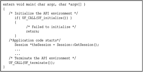
Creating a program environment for reusable code
-
3.
Replacing hard-coded inputs with variables. A journal file records all the macro commands, which are the operation steps that the software takes while modeling the product. During the process, all the expressions and associated functions in the form of “hard numbers” are recorded, as shown in Fig. 4. To make use of the CDM parameters and their values, those hard-coded inputs must be replaced with variables that are to be imported into the generated model from CDM data files as expressions. Note that the variable names defined in the reusable program, which are to be interpreted in the NX API functions as modeling expressions, have to be associated with the corresponding variables to be imported from the CDM.
Fig. 4 
Replacing hard-coded functions with variable input
-
4.
Deleting unnecessary data and functions. As the journal file is developed during the process of creating a model through a GUI, it records graphical operations as well, such as modeling view changes. These operations are not necessary for the reusable modeling program, and should be deleted. The journal file also records the intermediate and temporary functions and variables generated, as shown in Fig. 5. Since such information is not required in the reusable program code, it needs to be removed.
Fig. 5 
Deleting unnecessary data and function
-
5.
Grouping similar sections and functions together. A journal file records the model development process step by step, and thus keeps track of each individual process. Hence, a journal file often contains repetitive functions in the form of step-by-step incremental commands. In order to simplify the reusable code and enhance the efficiency of execution, all the repetitive functions and even sections are restructured as logic loops in the compiled program and sorted out together. Some commands have to be cleaned up, as shown in Fig. 6. The incremental expressions are also examined, and repetitive steps are replaced by combined equivalent cycles; again, if possible, always replace “static” numbers with variables.
Fig. 6 
Grouping data sections and functions together
-
6.
Associating the program code with appropriate “.dll” files. In the NX environment, when the journal file is recorded, it includes lists of all the header files required. In order to compile the program code, the header files need to be included; the corresponding “.dll” files (dynamically linked library files) are also to be included in the program’s compiling and debugging directory.
-
7.
Maintaining associative relations among design parameters. The associative relationship among design features can be maintained by developing a semantic map with a well defined and semantically interconnected design parameter scheme. The parameters are interconnected with engineering design concepts and constraints. With well-defined parameters, constraints and interdependencies between various features can be easily verified, checked, and maintained.


7 Case Study
The proposed method is applied for the design of separator vessels, which are used in many processing industry plants. There are various types of separators, including horizontal, vertical, and spherical. Separators are designed and manufactured taking into account the specific advantages and limitations of different configurations. The basic criteria for the selection of configuration are optimized lifecycle cost, operational safety, and accordance with design codes and standards for the required design domain. Separators are usually customized according to the specific operational requirements, and thus every separator requires particular design, but the overall design procedure and engineering considerations are similar. Thus, it is convenient to automate the design processes with a common programmed procedure.
7.1 The Case Set: Horizontal Separators
Figure 7 shows the basic layout of a horizontal separator [14]. The mixed flow of gas and liquid enters the separator and impacts on the inlet diverter, causing a sudden change in momentum and hence the preliminary separation. The larger droplets of liquid then separate over the gravity settling section and fall to the bottom liquid collection section. The liquid is given enough retention time for the dissolved gases to escape from the liquid gathered at the bottom and to collect in the vapor space above.

Layout of a horizontal separator
A separator vessel is designed according to gas capacity constraints. Each type of separator has its own merits and drawbacks. The major advantage of horizontal separators over vertical ones is that they are compact and less expensive for the required gas and liquid flow rate, and are more effective in cases with high gas–liquid ratio and foaming crude. Because of the large liquid–gas interface in a horizontal separator, there are more opportunities for gases to escape and more time for the liquid droplets to settle down. However, horizontal separators cannot handle solid sediments as well as vertical separators can. Vertical separators offer more liquid surge capacity than similar horizontal vessels for a steady-state flow rate. Under normal conditions, horizontal separators are better for oil–gas separation of high gas–oil ratios. They are also better for handling problems with emulsions or foam.
Separator vessels are designed according to the American Society of Mechanical Engineers’ boiler and pressure vessel code (ASME Code), section VIII. Pressure vessels are designed to withstand the loadings exerted by internal and external pressures, weight of the vessel, reaction of support, and impacts. Temperature, pressure, and feed composition and its mass flow rate are considered in the selection of type and the design of the vessel, and to come up with the dimensions of the vessel. For this particular study, the only loads considered are internal pressure and temperature. In general, vessel size is decided depending upon the flow rate requirement. For horizontal vessels, the support dimensions are standard and are based on the vessel diameter. During the initial product development stage using engineering design formulae and industrial standards, all the required parameters associated with the separator are calculated. By programming in C++, the above-mentioned design calculations for the separator vessel design are implemented as the embedded engineering knowledge in a program. In a typical application scenario, the designer is provided with operating conditions for the separator vessel in the field. The first task for the designer is to select the type of vessel required; in this case it is either a vertical or a horizontal vessel. The input requirements include flow rate, fluid properties, and working conditions such as pressure and temperature.
In this study, designs for vertical and horizontal separators are developed according to the same set of operating conditions and requirements. The embedded calculation programs have been written generically to handle different designs. The design input requirements used by the designer for designing the separator are given in Table 1.
7.2 Application in CAD Environment for the Data Structure
In the separator case study, the flow of the design process implemented by the program is set up to follow the generally accepted design procedure (ASME pressure vessel design code, section VIII) to solve an engineering problem. First, all the input values are converted from field units to the unit category used for calculations; in this case all the calculations are made with SI units. Next, the relevant nongeometric parameters, associated with operation and the fluid flow, are calculated. These parameters include gas flow rate, liquid flow rate, maximum allowable working pressure, and allowable stress values. They constitute the engineering information essential to calculating the geometric parameters required to build the CAD model for the required type of vessel, and further the FEM and CAE models. All the standard sizes for the components such as vessel diameter and nozzle sizes are stored in external files and can be modified, as per the requirements, by the user. This provides a flexible option for the user to design the vessel using the available standardized elements or components in the inventory. The calculation steps for the vertical and horizontal separator vessels are the same; the difference is in the design of the support, considering the different requirements. For a vertical vessel, a supporting skirt is used, for which design equations are coupled with standard sizes, whereas for a horizontal vessel, saddles are used and standardized for the given vessel diameter. Some of the assumptions made for the design process are: (1) the vessel is designed for the loading of internal pressure; (2) the vessel is designed with essential working components; (3) the pressure and temperature are assumed to be uniform; and (4) design is only for static loading.
After the engineering calculations, the next step of the design process involves a complete conceptual design model. In this step, based on the preliminary calculations, a mid-plane conceptual CAD model in a thin shell is constructed. This is a simplified model of the vessel utilizing the parameters determined from the engineering calculation program, as discussed above, and forms the basic structure of the vessel with the operating essentials. This model is created for the initial CAE verification of the design vessel and the development of the basic vessel shell structure. The FE model for this stage contains only 2D elements; the simulation time (or computing time for solving the FE model) is thus much less than that for an equivalent 3D solid model. The use of a mid-plane analysis cycle reduces the conceptual design time, considering the numerous iterations of design changes required in the early design stages. Figures 8 and 9 show the mid-plane CAD model and the CAE result. They also provide the concept design for the overall structure and can be used to create an early estimation of manufacturing expenses based on material requirements and manufacturability.

A separator’s conceptual mid-plane CAD model

Von Mises stress analysis results via Nastran with the conceptual mid-plane model (MPa)
To make any changes regarding the design during iteration, the designer is given design-specific choices such as geometric changes, functional changes, or direct changes to specific parameters. Again, depending upon the requirements and the corresponding changes made by the user, the program code regenerates the new parameter values and a new CDM. Older versions of the CDM are stored separately in order to maintain design records for previous iterations with the help of a file-handling mechanism.
7.3 Detailed Design for the Sample Separator Design
Once the conceptual mid-plane model is deemed acceptable, a 3D CAD model is generated and the corresponding 3D FE analysis is performed using the detailed CDM to perform the final analysis iterations. Similar to the mid-plane design process cycle, all the models are automatically generated using external API functions. Design changes are handled in a similar manner. In addition, at this time the user can still return to the mid-plane conceptual stage to change the basic structure and start the process again. The design process goes through a number of iterations until the results obtained are within an allowable stress limit. Figures 10 and 11 show the final CAD model and CAE result. The final result, based on the 3D FE model, shows the maximum stress and deformation values along with their locations. Just like the mid-plane conceptual phase, CDM files in each design iteration phase are maintained for records. Once the design model and the CAE results are finalized, the manufacturing drawings generated from the 3D CAD solid models and the final CDM data can be handed over to the downstream manufacturing engineer for further use.

Detailed 3D solid CAD model

Von Mises stress analysis results from detailed 3D model via Nastran (MPa)
7.4 FEA Details
The current finite element method used for CAE is based on a division of the design model into smaller elements and a calculation of the loads associated separately for each element, followed by a combination of the various results for the entire model to get final results. Design of the separator vessel was done under the loading of internal pressure and temperature. All the loads on the structure are static and the material is assumed to be homogeneous and isotropic.
The first step of the analysis requires meshing the available design CAD model into suitable elements. One of the important factors for meshing is to select an optimum mesh size. The mesh element size has to be small enough to produce reliable results, but should be big enough, so that it will take minimum computational time. For any given vessel design, the smallest features of the model are the various thickness associated with the nozzles and vessel body. In the case of mid-plane model mesh, each part of the model is meshed separately to assign specific mesh and physical properties. Well-defined objects during the CAD modeling process make it easier to map those geometry elements with the corresponding mesh properties. Mapping of information between CAD and FE software modules can be achieved by associating those similar sets of input parameters corresponding to individual objects within both applications through a neutral and centralized data structure (the CDM file) [5].
In the preliminary design stage with the mid-plane mesh model, as each design object has no physical thickness associated in the form of geometry, the thickness attribute has to be added in as a parametric physical property. The associativity between various design features in the mid-plane model is maintained by connecting them with the help of grid elements. The connecting mesh elements are massless and rigid, and thus only serve the purpose of transmitting the loads; they do not affect the structural integrity of the model.
In the detailed design stage using the 3D solid model, mesh size was chosen to obtain uniform meshing for those small features, which would ensure their mesh grids are compliant with the other larger features. In the mesh modeling process for the current case study, the mesh creation is made automatic by using NX Open coupled with parametric modeling; however, various physical and material properties need to be assigned manually. The element type used for meshing is tetrahedral, which achieves a uniform distribution around openings and corners as well as controlling the maximum available nodes. Next, the mesh model is applied with specific loads and constraints at the required locations automatically by running the reusable program compiled with NX Open API and parametric modeling functions using the CDM. Figure 12 shows the constraint and load map for a horizontal separator analysis model. Internal pressure is applied on the main vessel body as uniformly distributed load directed outward from the vessel surface. The temperature is also applied to the vessel body and is assumed to be uniformly distributed over the entire surface. A vessel support base at the ground end is given fixed constraints to represent fastening. The nozzle ends are constrained for axial movement along the pipe continuation in respective dimensions. The model then goes through static analysis calculations and results in the form of maximum Von Mises stress and maximum deformation are obtained (see Fig. 11).

Load and constraint model
The designer observes the results to judge the validation and the expected ranges of parameters based on the constraint settings. The loading conditions can be modified, and the analysis can be repeated to re-evaluate the solution. In the case of interpolated continuously changing loads and constraints, an iterative solver should be used to get a more refined and accurate solution.
7.5 Expansion of the Case Study to Vertical Separators
To test the general applicability of the proposed method to different product configurations, the same design development structure is used to design two different types of vessels with some conceptual design differences and considerable geometric differences. Figure 13a shows the basic layout of a vertical separator along with various computer models involved in the design process. For a vertical separator, the mixed liquid and gas flow enters the vessel from the side and impacts the inlet diverter. The initial gross separation happens at the inlet diverter. The liquid droplets fall down by gravity in the collection section. There are a few internal components in the collection section, such as the vortex breaker for the outlet; aside from that, this section is just a storage space for liquid designed as per the required retention time. The design should provide enough retention time, so that liquid should reach equilibrium and dissolved gases should rise upward to the vapor space.

Example vertical separator design and analysis results. a Layout of a vertical separator. b Mid-plane 3D detailed CAD models. c Mid-plane CAE analysis. d 3D detailed CAE anaysis
While rising up with the gases, the heavier liquid droplets fall to the collection section by gravity only; those droplets having a very small diameter (less than 100 μm, approximately) are usually carried by the gases until reaching the mist extractor. When gas passes through the mist extractor, these small droplets collide with the mist extractor coalescing section and fall downward to the collection section owing to lost momentum. Vertical separators are used for a flow with low or medium gas–liquid ratio. A vertical separator fitted with a false cone at the bottom can be effectively used to separate heavier solid particles such as sand and other sediments. Thus, in case of a flow with a small amount of sediment, residue can be effectively handled by the vertical separator. In the case of a low oil–gas ratio, vertical vessels are more effective. They can also be used as gas scrubbers where only fluid mists need to be removed from the gas, which demands extra surge capacity.
For the design of a vertical separator, a liquid capacity constraint is used because of the assumed higher liquid-to-gas ratio. Locations of all the nozzle openings for a vertical separator are usually fixed and are subject to change only because of major installation problems. A support skirt for the vertical vessel is custom designed for each vessel depending upon the weight load and momentum. In normal practice, external wind pressure or momentum has to be considered for the design, as the whole structure is considered to be a “column.” Regarding nozzle locations for vertical vessels, locations for manholes and gas outlets are fixed. For fluid and liquid nozzle opening locations, only height is fixed; peripheral location depends upon ease of installation. The design process for the vertical separator follows the same procedure as the horizontal separator. Figure 13b shows the mid-plane thin shell model as well as the 3D solid detailed model. The CAE analysis results based on the mid-plane mesh model are given in Fig. 13(c), while the 3D results are shown in Fig. 13d.
8 Advantages and Limitations
The proposed design method is an innovation beyond the conventional design process with CAD and CAE tools used separately. The product development time, especially the effort associated with cyclic CAD modeling and CAE analysis, can be greatly reduced. For example, running automated design and analysis for one cycle with the given case takes about 25 min after the development of the reusable programs, which include modules for CAD construction and CAE analysis. In contrast, the interactive approach takes 6 h for a skilled user to run the same procedure. However, the automated approach requires CDM construction and code preparation, which takes a one-time effort of 12 h initially. If the cycles of CAD and CAE activities require several rounds, this one-time effort can easily be justified, as subsequent cycles will save quite a bit of time. Potential time saved can be likened to how much a computerized numerical control (CNC) metal cutting method can save in comparison to manual machining methods.
Since the proposed process makes better use of integrated CAD and CAE software capabilities, it helps reduce the modeling and analysis time significantly via the use of parametric and procedural knowledge captured in much shorter program development time, while still maintaining the traditional design procedure. The journaling application for program development clearly reduces the need for programming expertise as well as the development time associated with the generative CAD/CAE approach. The method proposed here also provides the flexibility to handle complex modeling and analysis problems. The method makes it easier than before to capture modeling and analysis procedural knowledge as well as to make it reusable.
Parametric CAD models represent a smart product representation at a point of time. Procedural models reflect the product construction operations over a period of time. They are complementary and cannot replace each other. The proposed method leverages both the knowledge representations and processing mechanisms. Hence, it makes a unique contribution to this aspect of design methodology.
The use of a CDM makes it easier to transfer and control the specific information associated with various models as well as coupling the computer modeling process with an engineering knowledge-embedded program. Parameter-based modeling and analysis facilitates changes associated with specific design features.
The limitation of this method comes from the restriction of the journal file: not all the software capabilities can be fully utilized with a journaling application, since it is not capable of recording every manual operation. Though the program created is controllable and changeable to a certain degree, it lacks ideal flexibility. However, the traditional limitation of using the journal files, i.e., repeating the exact scenario as recorded, has been significantly relaxed by incorporating parametric modeling capabilities. In the new method, so long as the design and analysis procedures are the same, and the parameters given are valid inputs, different products can be designed with the same generated program code. The parameter values can be checked upfront before being used in the automated procedure via a constraint-checking algorithm. Only those sets of parameter values that have satisfied all the constraints are listed in the CDM as the acceptable data sets to be used.
As the journal file itself has limited capabilities for data and file handling, after converting it into a reusable program, the program has to be associated with an external data repository (the CDM) and file management system to make it flexible enough to handle changes. This task requires programming skill. To adopt the process, engineers will need to go through certain initial training and must understand software API programming.
9 Conclusion and Future Work
An innovative design process integration mechanism has been developed to efficiently create a reusable program structure obtained by editing journal files where the procedural engineering knowledge is embedded and by incorporating parametric modeling knowledge. With this novel mechanism, this chapter has explored a systematic automation method for knowledge capture and reuse via CAD and CAE programming. This method is able to improve the efficiency of the overall product development process. The use of a common parametric data model, which semantically connects CAD and CAE models, enables the designer to have better control over the process. By changing the design contents and parameter values, an automatic design process with minimal human interface is proposed and a demonstration case developed. The adaptive nature of the proposed method enables faster development of those products that have relatively clear development strategies and processes. The proposed method offers parametric flexibility for different design applications. The method enables the automation of design modeling and analysis processes more systematically, effectively, and conveniently.
Ideally, in the proposed method, the knowledge can be captured in the form of modular structures coupled with optimization algorithms and decision-making procedures and matrices. This element of the method has to be explored in future work due to limitations on available research resources. Future work is also necessary for refining the data and knowledge management capability with more generic program code development.
References
Bossak MA (1998) Simulation based design. J Mater Proc Technol 76:8–11
Cao BW, Chen JJ, Huang ZG, Zheng Y (2009) CAD/CAE integration framework with layered software architecture. In: Proceedings of 11th IEEE international conference on computer-aided design and computer graphics. Huangshan, China
Chen G, Ma YS, Thimm G, Tang SH (2004) Unified feature modeling scheme for the integration of CAD and CAx. Computer-Aided Des Appl 1:595–601
Chen G, Ma YS, Thimm G, Tang SH (2006) Associations in a unified feature modeling scheme. J Comput Inf Sci Eng 6:114–126
Gujarathi GP, Ma YS (2011) Parametric CAD/CAE integration using a common data model. J Manuf Syst 30:117–186
Hoffmann CM, Kim KJ (2001) Towards valid parametric CAD models. Computer-Aided Des 33:81–90
Johansson J (2009) Manufacturability analysis using integrated KBE, CAD and FEM. In: Proceedings of the ASME international design engineering technology conference, DETC 2008, vol 5, pp 191–200
Mital A, Desai A, Subramanian A, Mital A (2008) Product development a structured approach to consumer product development design and manufacture. Elsevier, Oxford
Monedero J (2000) Parametric design: a review and some experiences. Autom Constr 9:369–377
Pinfold M, Chapman C (2001) The application of KBE techniques to the FE model creation of an automotive body structure. Comput Ind 44:1–10
Radhakrishnan P, Subramanyan S, Raju V (2008) CAD/CAM/CIM. New Age International, Daryaganj, Delhi
Shah JJ, Ntylä MM (1995) Parametric and feature-based CAD/CAM: concepts, techniques, and applications. Wiley-Interscience, New York
Shephard MS, Beall MW, O’Bara RM, Webster BE (2004) Toward simulation-based design. Finite Elem Anal Des 40:1575–1598
Stewart M, Arnold K (2009) Gas–liquid and liquid–liquid separators. Gulf Professional Publishing, Oxford
Su D, Wakelam M (1998) Intelligent hybrid system for integration in design and manufacture. J Mater Proc Technol 76:23–28
Susca L, Mandorli F, Rizzi C, Cugini U (2000) Racing car design using knowledge aided engineering. Artif Intell Eng Des, Anal Manuf 14:235–249
Tomiyama T, Gu P, Jin Y, Lutters D, Kind CH, Kimura F (2009) Design methodologies: industrial and educational applications. CIRP Annals Manuf Technol 58:543–565
Xu X, Weiss U, Gao G (2002) The integration of CAD/CAM/CAE based on multi-model technology in the development of cylinder head. J Autom Technol 3:47–52
Zeng S, Peak RS, Xiao A, Sitaraman S (2008) ZAP: a knowledge-based FEA modeling method for highly coupled variable topology multi-body problems. Eng Comput 24:359–381
Author information
Authors and Affiliations
Corresponding author
Editor information
Editors and Affiliations
Rights and permissions
Copyright information
© 2013 Springer-Verlag London
About this chapter
Cite this chapter
Gujarathi, G.P., Ma, YS. (2013). A Smart Knowledge Capturing Method in Enhanced Generative Design Cycles. In: Ma, Y. (eds) Semantic Modeling and Interoperability in Product and Process Engineering. Springer Series in Advanced Manufacturing. Springer, London. https://doi.org/10.1007/978-1-4471-5073-2_11
Download citation
DOI: https://doi.org/10.1007/978-1-4471-5073-2_11
Published:
Publisher Name: Springer, London
Print ISBN: 978-1-4471-5072-5
Online ISBN: 978-1-4471-5073-2
eBook Packages: EngineeringEngineering (R0)