
Abstract
This paper presents design and the performance analysis of capacitive shunt RF MEMS Switch. Here, the proposed Rf MEMS Switch shows the low pull-in voltage i.e 11.97 V and performed at 38 GHz with high isolation. To improve the performance of antenna characteristics microstrip feeding technique and co-planar-waveguide transmission line feeding are used in this design process. The impedance matching of 50Ω in the antenna is depends on the width of the feed line can be observed through simulated smith chart by using the Ansoft HFSS simulator. The micro strip patch antenna exhibits a Return loss is − 12.4264 dB and exhibits resonance at 38 GHz and the band width frequency from 37 to 39 GHz.After analyzing the performance of the antenna then the antenna is integrated with RF MEMS capacitive shunt switch through co-planar wave guide transmission feedline technique. By integrating with switch there is a frequency shift OF 1 GHz toward right from 38 GHz in antenna. The resonance is occurred at 39 GHz with bandwidth frequency between 38 and 40 GHz. The antenna exhibits return loss is − 27.2666 dB at operating frequency 39 GHz with RF MEMS switch and total gain of the antenna at 38 GHz with angle of ϕ = 90° is 5.6671 dB. Thus the performance of the antenna is increased by integrating with RF MEMS switch. These type of reconfigurable antennas are used in high frequency applications at frequency range of Ka-band and in wireless communication applications and satellite communication.
1 Introduction
In wireless mobile communication and satellite communication system the microstrip patch antenna have attribute striking advantages such as low profile, light weight and easy fabrication .The microstrip patch antennas having limited bandwidth and are used for single mode operation with linear polarization. For switching capability between the two frequency bands reconfigurable antennas are preferable in some satellite communication systems. Generally, this switching can be attained by using p-i-n diode and FET switches but some researchers have proposed the latest RF MEMS switches for multi frequency band operations because of their precedence of higher isolation with better return loss and bandwidth compared to their semiconductor devices [1].In the recent years the RF MEMS switches are widely used in reconfigurable antenna due to their superiorities over the others such as small size, high quality factors and high linearity. Most of the antennas work in low frequencies due to lack of process consistence it means after fabrication of antenna the RF MEMS switches were just mounted in the circuit. When the operating frequency increases, the transmission coefficient becomes more sensitive due to variation in the thickness of the dielectric and dielectric constant more over the dielectric loss will be increases [2].There are different feeding techniques in designing the antenna they are (i) Microstrip feed line (ii) Co-axial feed line (iii) Aperture coupled feed line (iv) Proximity coupled feed line.
Here antenna designed is based on lateral etching to enhance the performance of the microstrip patch antenna on silicon substrate by micromachining techniques. The lateral silicon is removed underneath the patch to provide a cavity which Effects to produce a low effective dielectric region and this test results have increased the efficiency and bandwidth by 50% and 25% respectively. The rectangular patch antenna is considered with 0.243 mm width and 4.22 mm length having impedance matching of 50 ohms feedline operating at resonant frequency Ka-band [3]. Generally Bhatnagar’s posulates formula is used for transforming one design into another based on the height of the substrate to the guided wavelength and height scaling factor. In this, they followed the same Bhatnagar’s Postulate principle for exacting the new formulae for the feed line because the Bhatnagar’s postulate is limited only for patch. By this the feedline provide good impedance matching and good results [4].. In this work they presented the design and analysis of reconfigurable antenna which consists of pair of circular patches and RF MEMS switches to achieve pattern reconfigurability at frequency range of 1–10 GHz in Ansys HFSS simulator. The first switch either second switch is actuated shows pattern reconfigurability at 2.3 GHz and 3.4 GHz. In terms of return loss and pattern reconfigurability the antenna is analyzed for L and S bands [5]. To meet the antenna design aspects and performance of the antenna in terms of bandwidth and efficiency are increased by using selectively reducing the dielectric constant in specific regions for high index materials. There is an improvement in bandwidth of 64% from values 1.4-2.3% and efficiency by 28% from values of 66–85% respectively between the high index patch antenna and micromachined scaled [6]. Bo Pan proposed a novel micromachined air elevated patch antenna design, analysis and fabrication by using unique feeding technique and substrate removal methods. It demonstrates a fractional Bandwidth of-10 Db–10.5% and 9.5 dBi directivity for an elevation of 600 m [7].
In this work, To improve the efficiency and performance characteristics of an antenna in high frequency applications (i.e., Ka-Band frequency ranges from 27–40 GHz), integrate the antenna with RF MEMS capacitive shunt switch. By using RF MEMS switch the impedance matching will be acquired to maximum power transfer with low return loss. The ka-Band has many advantages compared with low frequency such as less interference and compact sizes. These types of antennas can be used for high frequency applications like 5G mobile communication and satellite communication.
The rest of the paper is organized as follows; the Sect. 2 illustrates the design of the rectangular patch antenna with RF MEMS switch and associated with impedance matching for the microstrip patch antenna techniques and transmission line methods involved in rectangular patch. The Sect. 3 provides the results and discussion and finally Sect. 4 is conclusion of the paper.
2 The Proposed RF MEMS Switch
2.1 Structure of Antenna
The pattern reconfigurable antenna is designed by using microstrip feedline technique. Here we considered rectangular patch mounted on the substrate. Silicon is taken as the substrate material because the antenna integrate with other circuit components with high material index of the component, without losing the advantage of with low index material so that the substrate region will house the radiating elements. The performance of the antenna is based on the impedance matching of the feeding line .The length and width of the rectangular patch can be calculated by using scaling factor which comes from the Bhatnagar’s postulate theory. The length and width of the microstrip patch can be calculated by using the known values operating frequency (f0) dielectric constant of the substrate material (εr) and height of the substrate.
2.2 Structure of RF MEMS Switch
In this we have considered the capacitive shunt switch with to integrate with the rectangular microstrip antenna [8]. The switch dimensions are exacted through optimization technique which is designed based on the operating frequency 38 GHz. The switch consists of perforations over the beam, to reduce the stiction problem. Appropriate materials are selected for the switch through the Ashby approach. The basic principle is both the ends of the switch is fixed, the beam actuated at the center of the beam and the capacitance is developed between the beam and down electrode. Initially the switch is in ON state with an air gap of 3 µm, after actuating the beam it undergoes 2/3rd displacement with pull-voltage of 11.987 V.
2.3 Procedure for Designing Antenna
-
Step 1 The width of the rectangular patch can be calculated by Eq. 1 [9]
$$W = \frac{c}{{2f_{0} }}\sqrt {\frac{2}{{\varepsilon_{r} + 1}}}$$(1)Here c - velocity of light in free space, \(f_{0}\)-operating frequency,\(\varepsilon_{r}\)-dielectric constant of the substrate
-
Step 2: The effective dielectric constant can calculated by Eq. 2 [10]
$$\varepsilon_{reff} = \frac{{\varepsilon_{r} + 1}}{2} + \frac{{\varepsilon_{r} - 1}}{2}\left[ {1 + 12\frac{h}{W}} \right]^{{ - \frac{1}{2}}}$$(2)where h is the height of the substrate, w is the width of the patch.
-
Step 3 The extension length \(\Delta L\) is calculated by Eq. 3 [11]
$$\Delta L = 0.412h\frac{{\left( {\frac{W}{h} + 0.264} \right)\left( {\varepsilon_{reff} + 0.3} \right)}}{{\left( {\frac{W}{h} + 0.8} \right)\left( {\varepsilon_{reff} - 0.258} \right)}}$$(3) -
Step 4 The correlation between the effective length of the patch and actual length is specified by Eq. 4
$$L_{eff} = L + 2\Delta L$$(4) -
Step 5 The effective length is given by Eq. 5
$$L_{eff} = \frac{{\lambda_{g} }}{2}$$(5)Guided wavelength in dielectric medium is given by Eq. 6
$$\lambda_{g} = \frac{{\lambda_{0} }}{{\sqrt {\varepsilon_{reff} } }}$$(6)$$\lambda_{0} = \frac{c}{{f_{0} }}$$(7)Where c is the velocity of light in free space and \(f_{0}\) is the operating frequency. The effective length is simplified from Eqs. 5, 6 and 7 [4].
$$L_{eff} = \frac{c}{{2f_{0} \sqrt {\varepsilon_{reff} } }}$$(8) -
Step 6 The actual length of the rectangular patch antenna is calculated by Eq. 9
$$L = L_{eff} - 2\Delta L$$(9) -
Step 7 Microstrip Feed Line Technique Here we considered a microstrip feed line techniques for the patch antenna. In this the rectangular patch is directly connected to the feed line. The impedance matching of the antenna depends upon the width of the feedline. The conductor width is smaller than the patch. The patch is mounted on the substrate and ground plane is taken under the substrate. The input signal is feed through the central conductor feed line to the patch. Thus the rectangular patch antenna radiates at operating frequency [12].
-
Step 8 The performance of the antenna is enhanced through Ansys HFSS simulator without switch (Figs. 1, 2, 3, 4, 5, 6 and 7).
Fig. 1 
Schematic view proposed Reconfigurable Patch antenna
Fig. 2 
Schematic view of proposed switch
Fig. 3 
Schematic microstrip feeding technique
Fig. 4 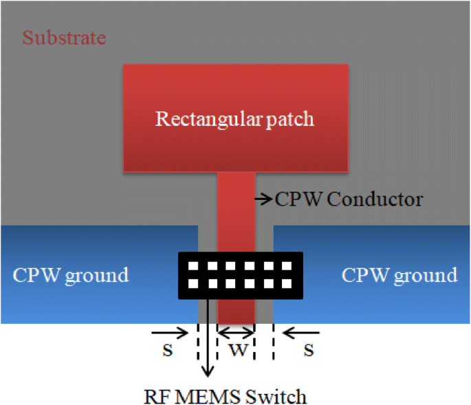
Schematic view proposed patch antenna with RF MEMS Switch
Fig. 5 
Voltage versus displacement
Fig. 6 
Displacement of beam for voltage
Fig. 7 
Source voltage versus switching time
-
Step 9 After that the antenna is integrated with RF MEMS switch for increasing the performance of antenna at high frequency. The Co-planar wave guide transmission line feeding is used for integration of RF MEMS switch to the rectangular patch antenna [13]. The switch is integrated having an impedance matching of 50 ohms with the central conductor.
-
Step 10 The switch acts as a actuator for the antenna, the characteristics of the antenna is analyzed using Ansys HFSS simulator (Table 1).
Table 1 Device specifications


3 Results and Discussions
3.1 Electromechanical Analysis
3.1.1 Pull in Voltage
The voltage required by the beam to pull down towards the electrode and exhibits minimum 2/3rd displacement in the gap between the beam and down electrode is known as pull in voltage or actuation voltage. The pull in voltage of the beam is given by [14]
Here k is the spring constant [15]
g is gap between the electrode and beam, \(\varepsilon_{o}\) permittivity in free space; an acutaion area i.e. is the width of the signal line and w is the width of the beam. A=W×w. The pull in voltage is measured as 11.97 volts and spring constant is 2.406 N/m.
3.1.2 Switching Time Analysis
The time taken by the beam to change its position from one state to another that time taken by the device is called switching time or switching speed. The switching time of the RF MEMS shunt switch can be calculated [16]
where VP -pull in voltage, Vs-supply voltage, Vs = 1.4VP
\(\omega_{0}\) Represent resonant frequency. Then switching time required by the switch is t s=0.19 ms.The resonant frequency given from the effective mass and spring constant
3.2 RF Performance of Antenna without switch
RF performance of the proposed microstrip antenna can be enhanced by using Ansys HFSS simulator (Eq. 8).
During the transmission there is a loss of RF input signal and reflected back at the input terminal due to impedance mismatching of the switch is known as Return loss. When the switch is in ON state the return loss is analyzed. The return loss should be < − 10 dB.It is defined as S11 [17]
The proposed rectangular microstrip patch antenna is having resonance at 38 GHz and exhibits return loss for RF input signal is − 12.4264 dB as shown in Fig. 8.

Return loss of patch antenna without switch at 38 GHz
The simulated smith chart of the microstip patch antenna is shown in Fig. 9, which inclined the impedance matching of the CPW central conductor i.e., feeding line. The impedance matching of 50Ω in the antenna at resonant frequency 38 GHz and exhibits magnitude of 0.2552 with RX 0.6044-0.10923.

Smith chart of antenna without switch
From the far field radiation pattern, the total directivity in co-polarization of the rectangular microstrip patch antenna without switch exhibits − 9.1722 dB at resonant frequency 38 GHz in the direction of θ=90°, ϕ = 90° in H-field as shown in above Fig. 10.

Co-polarization of antenna without switch in magnetic field
From the far field radiation pattern, the total directivity in cross-polarization of the rectangular microstrip patch antenna without switch exhibits − 9.1722 dB at resonant frequency 38 GHz in the direction of θ=90° ϕ = 85° in H-field as shown in above Fig. 11.

Cross-polarization of antenna without switch in magnetic field
In electric field,the total directivity in co-polarization of the rectangular microstrip patch antenna without switch exhibits − 4.1807 dB at resonant frequency 38 GHz in the direction of θ=90°, ϕ = 90° as shown in the far field radiation pattern, above Fig. 12.

Co-polarization of antenna without switch in electric field
In electric field,the total directivity in cross-polarization of the rectangular microstrip patch antenna without switch exhibits − 9.6792 dB at resonant frequency 38 GHz in the dCtion of θ=90°, ϕ = 90° as shown in the far field radiation pattern above Fig. 13.

Cross-polarization of antenna without switch in electric field
3.3 RF Performance of Antenna with RF MEMS Switch
Here the switch is integrated with the rectangular patch antenna by using coplanar wave guide transmission line feeding. The switch acts as regulator to the antenna for activating and deactivating and shifts in frequency shift and bandwidth. By using RF MEMS switch the performance of the antenna is increased and antenna frequency of applications will be increased. Below Fig. 14 show the simulated of patch antenna with RF MEMS switch when switch is in ON state.

View of simulated antenna with switch in HFSS
The proposed rectangular microstrip patch antenna with RF MEMS switch is showing resonance at 39 GHz it means by using RF MEMS there will be a frequency shift towards the right side. There is an increase in frequency of operation after integrating the switch. Now, the rectangular microstip reconfigurable patch antenna exhibits a return loss of − 27.2666 dB at 39 GHz in Fig. 15. Thus, in this aspect of RF performance of the antenna is improved.

Return loss of antenna with RF MEMS switch in ON state
From the above radiation pattern, the Fig. 16 shows the total RF gain of the reconfigurable antenna at operating frequency 38 GHz in all directions at an particular angle of 360° is 5.6671 dB.

Radiation pattern of antenna with switch
From the far field radiation pattern, the total directivity in co-polarization of the rectangular microstrip patch antenna without switch exhibits − 0.5062 dB at resonant frequency 38 GHz in the direction of θ=90°, ϕ = 90° in H-field as shown in above Fig. 17.

Co-polarization of antenna with switch ON state in Magnetic-field
From the far field radiation pattern, the total directivity in cross-polarization of the rectangular microstrip patch antenna without switch exhibits − 30.7478 dB at resonant frequency 38 GHz in the direction of θ=90°, ϕ = 90° in H-field as shown in above Fig. 18.

Cross-polarization of antenna with switch in Magnetic field
In electric field,the total directivity in co-polarization of the rectangular microstrip patch antenna without switch exhibits − 0.5062 dB at resonant frequency 38 GHz in the direction of θ=90°, ϕ = 90° as shown in the far field radiation pattern, above Fig. 19.

Co-polarization of antenna with switch in Electric field
In electric field,the total directivity in cross-polarization of the rectangular microstrip patch antenna without switch exhibits − 30.7478 dB at resonant frequency 38 GHz in the direction of θ=90°, ϕ = 90° as shown in the far field radiation pattern above Fig. 20.

Cross-polarization of antenna with switch in Electric-field
The above Fig. 21 shows the simulated graph of the reconfigurable antenna which is having the VSWR value of 1.7294-9 throughout the frequency range of 35 to 50 GHz at the operating frequency 38 GHz it is having 1.729

VSWR of the reconfigurable antenna with RF MEMS switch
4 Conclusions
In this paper, we have been designed the proposed rectangular microstrip patch antenna, extracted the dimensions based on the operating frequency 38 GHz and analyzed the characteristics of reconfigurable patch antenna by using Ansys HFSS simulator. Later the patch antenna is integrated with RF MEMS capacitive shunt switch and enhanced the characteristics of the proposed reconfigurable antenna through simulations. The performance of the antenna is increased in terms of return loss and gain and bandwidth. The return loss after integrating with MEMS switch the reconfigurable microstrip patch antenna exhibits return loss is − 27.2666 dB at operating frequency 39 GHz and total gain of the antenna at 38 GHz with angle of ϕ = 90° is 5.6671 dB and bandwidth frequency between 38 and 40 GHz.
References
A.K. Sharma, N. Gupta Impedance matching for RF-MEMS based microstrip patch antenna, in 11th International Conference on Electrical Engineering/Electronics, Computer, Telecommunications and Information Technology (ECTICON,https://doi.org/10.1109/ecticon.2014.6839775 (2014)
Z. Deng, X. Guo, H. Wei, J. Gan, Y. Wang, Design, analysis, and verification of Ka-Band pattern reconfigurable patch antenna using RF MEMS switches. Micromachines 7(8), 144 (2016). https://doi.org/10.3390/mi7080144
V.K. Singh, Ka-band micromachined microstrip patch antenna. IET Microw. Antennas Propag. 4(3), 316 (2010)
M. Mathur, A. Vats, A. Agarwal, A new design formulae for feed line dimensions of the rectangular microstrip patch antenna by using equivalent design concept, in International Conference on Signal Processing and Communication (ICSC).https://doi.org/10.1109/icspcom.2015.7150629pattern (2015)
A.K. Sharma, N. Gupta, Pattern reconfigurable antenna using non-uniform serpentine flexure based RF-MEMS switches, in PIERS Proceedings, pp 2840–2843 (2015)
I. Papapolymerou, L.P.B. Katehi, Micromachined Patch Antennas. IEEE Transactions Antennas and Propag 46(2), 275–283 (1998)
B. Pan, Yoon Yk, G.E. Ponchak, Allen et al., Analysis and characterization of a High-Performance Ka-band surface micromachined elevated patch antenna. IEEE Antennas Wirel. Propag.Lett. 5(1), 511–514 (2006)
E. Erdil, K. Topalli, M. Unlu et al., Frequency tunable microstrip patch antenna Using RF MEMS technology. IEEE Trans. Antennas Propag. 55(4), 1193–1195 (2007)
R. George, C.R.S. Kumar, S.A. Gangal, Design of a frequency reconfigurable pixel patch antenna for cognitive radio applications, in International Conference on Communication and Signal Processing, pp 1685–1688, April 6-8 (2016)
S. P. Singh, A. Singh, Design and fabrication of microstrip patch antenna at 2.4 Ghz for WLAN application using HFSS. IOSR J. Electron. Commun. Eng., e-ISSN: 2278-2834, p- ISSN: 2278-8735
H. Srivastava, B. Maity, A compact slotted h-shape microstrip patch antenna for wireless communication with microstrip antenna feed, in International Conference on Communication and Signal Processing, April 6-8 (2016)
S. Bisht, S. Saini, V. Prakash et al., Study the various feeding techniques of microstrip antenna using design and simulation using CST microwave studio Int J Emerg Technol Adv Eng 4(9), 318–324 (2014)
S. Nikolaou, D. Nickolas, Kingsley et al., UWB elliptical monopoles with a reconfigurable band notch using MEMS switches actuated without bias lines. IEEE Trans. Antennas Propag. 57(8), 2242–2251 (2009)
S.P. Pacheco, L.P. Katehi, C.T.C. Nguyen, Design of low actuation voltage RF MEMS switch, in IEEEMTT-S International Microwave Symposium Digest, vol.1, pp.165–168 (2000)
K.S. Rao, P.A. Kumar, K. Guha, B.V.S. Sailaja, K.V. Vineeth, K. L. Baishnab, K.G. Sravani,” Design and simulation of fixed–fixed flexure type RF MEMS switch for reconfigurable antenna”, Microsystems Technologies, june 2018
N.T. Lakshmi, S.K. Girija, R.K. Srinivasa, Design and analysis of CPW based shunt capacitive RF MEMS switch. Cogent Eng. 4(1), 1–9 (2017)
J.B. Muldavin, G.M. Rebeiz, High-isolation CPW MEMS switches, part 2: design”. IEEE Trans. Micro Tech. 48(6), 1053–1056 (2000)
Acknowledgements
The authors would like to thank NPMASS for providing the necessary FEM tools for design and simulations under NMDC.
Author information
Authors and Affiliations
Corresponding author
Ethics declarations
Conflict of interest
The authors declare that they have no competing interests
Additional information
Publisher's Note
Springer Nature remains neutral with regard to jurisdictional claims in published maps and institutional affiliations.
Rights and permissions
About this article

Cite this article
Mohan, C.L., Kavya, K.C.S. & Kotamraju, S.K. Design, and Analysis of Capacitive Shunt RF MEMS Switch for Reconfigurable Antenna. Trans. Electr. Electron. Mater. 22, 57–66 (2021). https://doi.org/10.1007/s42341-020-00212-0
Received:
Revised:
Accepted:
Published:
Issue Date:
DOI: https://doi.org/10.1007/s42341-020-00212-0