
Abstract
Traditional approach for design, operation and regulation of the nuclear plants is deterministic in nature where the principle of defense in depth governs incorporation of multiple barriers and levels of protection. Single failure criteria, redundancy, diversity, fail safe criteria, quality assurance, etc., form the major cornerstone of this approach for safety demonstration. Traditional approach, which is conservative and prescriptive in nature, has served well for high level of safety since the inception of nuclear industry. However, with the accumulation of operating experiences, insights obtained from the accidents in the nuclear plants and growth of the probabilistic risk assessment methods, there is an increasing trend to implement a risk-informed approach in the nuclear plants. Over conservatism built in design, operation and regulation can be addressed using quantitative insights on risk and uncertainty such that the system availability or performance can be enhanced without compromising the safety. This paper proposes an integrated risk-based approach wherein probabilistic risk assessment framework has been used along with the deterministic insights to give credit to the available design provision in the nuclear plants. The objective is to use the margins available with the existing design to demonstrate safety of the plant by using risk framework along with the improved understanding of uncertainty. The model and procedure, involved in the risk-based approach, have been demonstrated through a case study performed on an Indian research reactor.
1 Introduction
There are 449 nuclear power plants (NPPs) and 250 research reactors operating all over the world (PRIS: Power Reactor Information System 2018; Research Reactors 2018). These reactors have been built by using deterministic approach, which is basically conservative in nature (Deterministic Safety Analysis for Nuclear Power Plants 2010). The philosophy of defense in depth requires implementation of series of barriers and levels of protections towards eliminating chances of accidents (Defence in Depth in Nuclear Safety 1996). The principles of single failure criteria, redundancy, diversity, fail safe criteria form the basis of defense in depth strategy. This approach has served the purpose of designing, operation and regulation of the reactors exceedingly well, particularly given the fact that (a) the nuclear systems have evolved from a time when no or little experience was there on design, operation and safety insights, (b) non-availability of advanced computational tools and methods, (c) no formalized approach to address the uncertainty factor and (d) limited understanding of human factor, which is crucial for the safety of plant, particularly in understanding the common cause of failure. Even though the excellent safety record of nuclear industry is testimony to the successful application of deterministic approach, the incidents and accidents, particularly, the Three Mile Island (USA) in 1976, Chernobyl (Russia) in 1986 and Fukushima (Japan) in 2011 provided valuable insights on nuclear design, operation and regulation (A Brief History of Nuclear Accidents Worldwide 2018). The lessons learnt from there were valuable in understanding the limitation of current deterministic safety approach and made the nuclear industry to work on improving the current approach used for siting, design, operation and regulation of the nuclear plants. The first Probabilistic Risk Assessment (PRA) work (United States Atomic Energy Commission 1975; United States Nuclear Regulatory Commission 1995), performed on PWR and BWR plants, gave the momentum to the application of PRA for addressing the real-time issues. This work along with many publications from the International Atomic Energy Agency (IAEA) during early or middle 1990 and later 2000 onwards are testimony to the maturity and acceptance of PRA as a complementary framework to deterministic approach (Applications of Probabilistic Safety Assessment (PSA) for Nuclear Power Plants 2002) in nuclear industry.
This paper proposes an Integrated Risk-based Engineering (IRBE) framework, which is currently being developed in RRSD, BARC. The fundamental difference between the prevailing definition of risk-informed (where Probabilistic Safety Analysis or PSA insights form one of the inputs along with traditional deterministic approach in support of decisions) and risk-based (decisions based only on risk insights from PSA) approaches have been revisited to derive the proposed concept of IRBE framework. In IRBE, the traditional deterministic philosophy, like defense in depth, redundancy, diversity, fail safe features are implemented and reflected in PSA modeling (more effectively) towards arriving at a quantified estimate of risk/safety. It is different from the traditional definition of risk informed approach, as in IRBE, (a) the fundamental variables are modeled using probabilistic methods to reflect the uncertainty in data, (b) PSA framework is not playing merely a supporting or complementary or supplementary role to deterministic approach, rather it integrates the framework of deterministic and probabilistic aspects, (c) probabilistic criteria and goals are followed on conservative basis, e.g. instead of median or mean value, 95% bound brings in the required conservatism with real and quantifiable knowledge of variability of parameters, (d) for monitoring and feedback, advanced condition based or prognostic or data driven approach are envisaged and (e) human factor modeling is based on human model, instead of symptom based structure. The development of IRBE framework is in intermediate stage. In the present paper, only the model and procedure, considered in the framework, have been demonstrated through a case study based on Dhruva, an Indian research reactor.
2 Integrated risk-based engineering framework
2.1 The IRBE framework
In integrated risk based engineering approach, fundamental assumption is that deterministic and probabilistic aspects are integral to all the aspects of design, operation and regulation and they need not be seen in isolation as each one works with other and support the safety case. For example, a pump, which is designed to perform a safety function, say to provide the cooling flow at a given pressure, may fail to perform the function, which can be characterized by a probabilistic element called the probability of failure. Uncertainties associated with the probability are quoted in terms of a bound of (±) 5% along with the mean and median value. Hence, deterministic aspects are not complete without giving their probability of failure. Same argument is also applicable to other systems used in nuclear plant.
The IRBE approach, as given in (Fig. 1), proposes that (a) deterministic approach is the primary methodology that provides the building blocks for risk insight, though at qualitative level, (b) the probabilistic approach provides an effective and systematic framework for plant and performance integration and thereby enables derivation of quantitative estimates of safety, e.g. core damage frequency per year, system unavailability at lower level, etc. (c) The quantitative probabilistic success or failure criteria, again derived from the traditional deterministic quantitative health objectives (QHO), provides a robust basis in support of decisions, and (d) Human uncertainty analysis with enhanced scope through consciousness, cognition, consciousness, and brain (CQB) approach for quantitative modelling of uncertainties associated with human actions and (e) a systematic framework employing prognostics and health management (PHM) methodology for monitoring of not only the operation but also the degradation of structures, systems and components (SSCs).

Risk-based design approach
Hence, IRBE can be characterized based on the following criteria:
-
(a)
The fundamentals of science and engineering form the input to deterministic and probabilistic models.
-
(b)
The PRA framework captures the design and operational aspects for giving holistic and more effective integrated model of the plant.
-
(c)
Keeping in view of the traditional concerns of safety community, the IREB guideline is that the overall approach should work towards consolidating the defense in depth and should support and complement the defense in depth principles.
-
(d)
The improved framework available for uncertainty characterization in probabilistic approach should provide an effective tool to address the weakness associated with the considerations of ‘factor of safety’ in deterministic approach.
-
(e)
The definition of quantitative goals and criteria, represented as probabilistic variables are crucial for implementation in IRBE.
-
(f)
The probabilistic framework provides an effective integration of human factor into the plant risk model. Hence, IRBE requires concept of a robust human model developed from first principle since the existing human reliability analysis methods do not have an adequate human model.
-
(g)
The IRBE framework caters to design, operation and regulation, unlike the traditional risk-informed/risk-based approach which mainly focuses only on the regulatory aspects.
-
(h)
At the minimum, in the context of regulatory decisions, the IRBE can readily be employed as a part of the traditional approach to risk-informed decisions.
2.2 Risk metrics
The risk metrics form the basis of IRBE. This needs to be more conservative in line with defense-in-depth principles. In IRBE based design and operations, the quantitative criteria form the basis for licensing unlike the risk informed decisions, where the results of PRA just form one of the inputs in decision making. The level of defense in depth in risk-based approach is shown in Fig. 2. Based on the governing criteria, risk metrics have been developed. Figure 3a–c show the risk metrics for Core Damage Frequency or CDF, Large Early Release Frequency or LERF and risk, respectively, as part of defense in depth strategy. Probabilistic Safety Assessment provides a solid framework for risk quantification of the entire plant. It takes into account interactions and inter-connections between various safety systems.

Level of defences

a Level 1 target: CDF goals in IRBE, b level 2 target: LERF goals in IRBE and c level 3 target: risk goals in IRBE
2.3 Human factor modelling
The nuclear and aviation industry recognizes the importance of human factor considerations as human factor has been found to be one of the major contributors to accidents. The available literature shows that many approaches have been developed till date for human reliability analysis but only few of these are being used. Technique for human error rate prediction (THERP) (Swain and Guttman 1983), human cognitive reliability (HCR) (Hannaman et al. 1984) and the relatively recent one A Technique for Human Reliability Analysis (ATHENA) (United States Nuclear Regulatory Commission 2000) are some of the approaches being extensively used in nuclear industry. However, there is no consensus amongst the human reliability experts on any one approach. The major limitation of these approaches is that data and models have been, to a large extent, based on expert elicitation. This makes these insights very narrow and focused on the context of a situation. Simulator, experiments have also been used in these studies. However, in the absence of correlation between the field conditions and the simulator environment, these data will always be away from real-time scenario. Though the existing approaches try to model the human behaviour during normal and emergency condition, the human model, which should be the basis of these methodologies, is either weak or missing. This answers partly why the existing approaches either do not provide any satisfactory answer or comes with large uncertainty. In IRBE, a CQB based human model is proposed where the human model is developed around three elements that drive the human behaviour—consciousness, cognition and conscience operating at Brain or Mind. The most advanced approaches, for example HCR, recognize only the cognition part while in IRBE approach, all three Cs (consciousness, cognition and conscience) are being integrated for human factor modelling. The IRBE approach is made pro-active towards reducing the human error in real-time condition by its induction in selection, training, monitoring the performance and behaviour of the plant staff, making refresher training and behavioural trending as the integral part of the human factor management. All these aspects are made possible by CQB approach.
2.4 Prognostics and health management (PHM)
The major concern in defense in depth approach is to eliminate or reduce the risk to the public and property to as low as reasonably achievable (ALARA). However, after laying down the principles of defense in depth, there remains a big question, how failure occurs, how monitoring can be based on sound and robust methodology such that health management plan is implemented in a meaningful manner. For example, the current in-service inspection (ISI) methodology suffers from a drawback of non-coverage potential and does not provide assurance against identification of failure and its elimination. The present condition monitoring methodology does work towards giving indication of deterioration. However, the indications are often associated with large uncertainty as to how long the component will take to fail as these methodologies are based on one precursor like vibration, temperature, etc. Moreover, the science part of the correlation between the precursor trend and the level of damage is not understood fully. Hence, there is need of an improved methodology that provides a robust science based framework predicting the degradation trend and thereby incipient fault/failure with the required confidence levels such that real-time planning and management can be put in place to eliminate or reduce the consequences of failure. The PHM approach provides degradation monitoring of at least 20% safety critical SSCs identified using importance measures generated in Level 1 PRA. There are three approaches to implement PHM (a) data driven, (b) physics of failure (POF) and (c) fusion. PHM implementation is being employed in structural system monitoring like hydraulic dams, bridges, mega structures on one hand and aviation, space applications on the other. PHM is extensively being researched and implemented on electronic systems as well. If we look at nuclear industry, the ‘monitoring and feedback’ forms an element of risk-informed approach and the PHM framework provides an effective mechanism to strengthen this element. The IRBE seeks to implement the PHM as a proactive and not a reactive approach to monitor not only the performance of SSCs but to employ POF based approach for degradation monitoring and prediction of failure with a level of uncertainty that is beneficial to plant management towards mitigation of consequences.
3 Case study: design evaluation of shutdown system in Dhruva research reactor
A case study is performed for studying whether credit of a slow acting shutdown system should be taken into account or not for a reference plant. In this context, an approach, which employs primarily PSA model supported by deterministic study that includes reactor physics coupled with thermal hydraulic, is discussed in support of crediting the design features already available and demonstrating the enhanced safety of the plant.
3.1 Problem definition
The case study is performed on Dhruva, an Indian research reactor, which is a tank type vertical reactor with metallic natural uranium as fuel, heavy water as moderator, coolant and reflector, giving a maximum thermal neutron flux of 1.8 × 10¹⁴ n/cm2/s (Agarwal et al. 2006).The reactor power regulation is achieved by varying the moderator level with constant inflow and variable outflow. The arrangement for achieving this level control is shown in Fig. 4. Three independent channels of instrumentation are provided for every reactor/process parameter. When any parameter exceeds its pre-set value, reactor trip signal is generated on two out of three co-incidence logic. The instrumentation with adequate redundancy covers monitoring and recording of all important reactor/process parameters and provides audio-visual alarm annunciation to make plant personnel aware about the operational health of each system/subsystem and its various components at all times. Primary shut down system (PSS) of the reactor is composed of 9 cadmium shut off rods. Fast shut down of the reactor is achieved by gravity insertion of all these 9 rods into the core. Minimum reactivity worth of all 9 rods is about 90 mk. The backup shutdown system (BSS) is dumping of the heavy water moderator from the reactor vessel to the dump tank in order to bring down moderator in the reactor vessel to a pre-determined level. Dumping of the heavy water moderator is achieved by opening three dump and three control valves. Dump valves, which remain fully closed during reactor operation, are air to close and spring to open, thus providing a fail-safe feature. The dump valves are provided in parallel with the control valves, which control moderator out flow from the vessel. All the six valves fly open on a completed reactor trip signal.

Simplified schematic of Dhruva considered for this case study
In this nuclear reactor, PSS and BSS are actuated simultaneously by protection channels on a reactor trip/shutdown signal. However, the design safety demonstration has originally been performed considering the deterministic approach by taking credit of PSS only. The BSS is not credited as it is relatively slow as compared to the PSS. The objective is to evaluate the adequacy of BSS as second level of defense, i.e. as secondary shutdown system (SSS) in the design of protection function of the reactor and thereby use the available safety margin towards demonstrating the enhanced safety of the reactor.
3.2 Risk assessment
In the traditional deterministic approach, a set of initiating events (IEs) is selected to demonstrate the safety of the reactor. Some of the salient features related to this analysis are as follows:
-
1.
The plant is designed to cater (a) uninterrupted core cooling in all conditions including the decay heat removal in shutdown state, (b) efficient termination of the neutron chain reaction and power regulation and (c) protection of occupational worker as well as public against ionizing radiation.
-
2.
The fuel clad temperature forms the major design limit along with parameters related to the structural integrity and safety.
-
3.
Major postulated initiating event (IE) groups are loss of offsite power (LOOP), loss of coolant accident (LOCA) and loss of regulation incident (LORI).
-
4.
The qualitative, conservative, probabilistic criteria are used to categorize design basis events (DBE) and beyond design basis events (BDBE).
-
5.
The conservative failure criterion and boundary conditions are used.
-
6.
Design of protection safety system employs 2-out-of-3 voting redundant logic.
-
7.
Surveillance programme includes (a) online monitoring of safety parameters and automatic actuation of safety provisions on reaching safety limit settings, (b) in-service inspection of structural systems and (c) maintenance management, which addresses issues related to repair/replacement due to degradation/ageing.
-
8.
Safety limits and limiting conditions for operations are derived from the safety analysis report (SAR).
This case study has been performed to demonstrate how the available safety margin in shutdown capability (in terms of moderator dumping) can be utilized to further strengthen the safety of the reactor. Target risk metric considered for the case study is given in Table 1 (Basic Safety Principles for Nuclear Power Plants 1999; Safety of Research Reactors 2016). Three postulated IEs—LOOP, LOCA and LORI have been selected for this design evaluation. PRA, which has been performed for this reactor as a part of this evaluation, shows that the available safety margin, in the form of dumping system capability, is required to demonstrate the safety of the plant.
3.2.1 Major safety functions and associated failure probability
In this section, the major safety functions, that need to be considered in the case study, and the associated failure probability are given in Table 2. The fault tree analysis technique is employed for estimating the system failure probability or unavailability. As far as possible the data obtained from plant records are used in the analysis. In case the plant data are not available, then data from generic sources are used. Safety systems/functions, mentioned in the 1st column of Table 2, form the header event in the fault tree analysis.
3.2.2 Initiating event analysis
During loss of off-site power (LOOP) scenario, reactor trips due to simultaneous actuation of primary and backup shutdown system (i.e. fast insertion of primary shutdown rods and relatively slow action involving opening of dump and control valves in moderator system) and the main coolant pumps also trip and shutdown cooling pumps are automatically pressed into operation by the protection logic of the reactor. Figure 4 shows a simplified schematic of the reactor showing the reactor, coolant and moderator system (primary and backup) and emergency core cooling system. In this reactor, coolant and moderator system are interconnected such that any loss in the coolant inventory is made up by the moderator system.
Three major initiating events, viz LOOP, LORI and LOCA are revisited to evaluate the shutdown capability of the plant (a) taking credit of moderator dumping and (b) without taking credit of moderator dumping (i.e. only primary shutdown system is considered for reactor tripping/shutdown).
3.2.2.1 Loss of off-site power (LOOP)
-
(a)
Fault tree analysis
Two feeders supplying the electrical power to the plant sub-station form the off-site power or Class IV power supply to the plant. On sensing failure of off-site power by plant protection logic, the reactor trips automatically and the station captive power system, referred as Class III power supply system, caters to plant essential loads required to be operated during the off-site power failure condition. LOOP event tree has been made for two cases, viz. without crediting the moderator dumping system, i.e. BSS (Fig. 5) and with crediting the BSS (Fig. 6). Based on 15 years of plant records, the loss of off-site power failure frequency has been estimated to be 1.2/year. The extended failure of both class IV and class III power leading to the station blackout condition is considered critical. However, due to availability of separate dedicated two DGs which feed the makeup pump motors for Overhead Storage Tank (OHST) enable continuous make up requirement of OHST. This in turn ensures the operation of two shutdown core cooling pumps on turbine prime movers.
Fig. 5 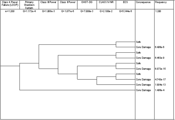
Event tree for LOOP—not crediting moderator dumping
Fig. 6 
Event tree for loss of off-site power (crediting moderator dumping)
-
(a.1)
LOOP—no credit to moderator dumping
From the accident sequence analysis of LOOP with no credit of BSS, It can be inferred that the PSS unavailability is an overriding state. Due to this, LOOP contribution to Core Damage Frequency is 1.47 × 10⁻⁴/year. The traditional deterministic approach does not take credit of moderator dumping as it is slow in terms of reactivity addition, which may rise the thermal parameters more than the stipulated value.
-
(a.2)
LOOP—taking credit of moderator dumping
For crediting the moderator dumping, the original thermal hydraulic calculations (coupled with neutronic) are revisited to analyze the margins. It is found that, given the flow coastdown characteristics of the main coolant pumps in conjunction with fine tuning of available margins, the moderator dumping, even though slow, compared to primary shutdown system, does not lead to fuel failure. The details of reactor physics and thermal hydraulics computation are presented in the following section.
From the accident sequence analysis of LOOP with credit of BSS, contribution of LOOP towards core damage frequency (CDF) is estimated to be 6.83 × 10⁻⁶/year, which is much less than the previous case where credit for moderator dumping is not taken.
-
(a.1)
-
(b)
Deterministic analysis (flow coast-down)
The transient is assumed to be initiated by LOOP to the main coolant pumps (MCPs) of Dhruva at 100% FP (i.e. 100 MW), which results in immediate loss of coolant flow to the fuel assemblies. Due to the provision of fly wheels, coupled to the main coolant pump shafts, the coast-down flow (gradual decrease in coolant flow) is considerably improved. There will, however, be a finite delay time in the actuation of reactor trip and subsequent decay of reactor power depending upon the parameter initiating the reactor trip. This gives rise to the possibility of rise in temperature of fuel assembly as well as coolant from the normal operating values during the transient.
-
(b.1)
Modeling
In the analysis, the credit of primary shutdown system (PSS), which comprises of nine shut-off rods, is not taken. Hence, the reactor is tripped by the automatic dumping of heavy water through the control and dump valves. The data of moderator level in reactor vessel (RV) as a function of time, after the actuation of dumping, are used to estimate the temporal variation of negative reactivity introduced into the core as given in Fig. 7a. The reactivity profile is then used in the point kinetics code SACRIT (Singh et al. 2013) to generate the power profile after the initiation of dumping event, as given in Fig. 7b. This power profile is used as an input to the computer code FCOAST (1960) to carry out the flow coast-down analysis. FCOAST solves the time dependent heat conduction equation by Finite Difference Method (FDM). In the simulation, (i) radially the fuel is divided into five meshes while the clad and coolant are divided into 1 mesh each and (ii) axially the fuel, along with the clad and coolant, is divided into thirty meshes. Hottest pin in the reactor core associated with average coolant flow per pin is chosen to calculate the maximum possible temperature of fuel, clad and coolant during the transient. Following the off-site power failure and subsequent flow coast-down, the first trip to get registered is “UNDER VOLTAGE” with an actuation delay of 0.6 s. This is followed by another trip on “LOW ∆P ACROSS REACTOR”, which is registered with an actuation delay of about 3.35 s. Since, the present analysis is based on “single failure criterion”, the first trip is ignored. Maximum channel power is considered to be 1170 KW at 100 MW reactor power and trip set flow is 430 lpm. Various other input parameters, used in the analysis, are given in Table 3.
Fig. 7 
Temporal variation of a heavy water level in RV and b reactor power after the dumping action
Table 3 Input parameters used in the flow coast-down analysis -
(b.2)
Results
The results for the most conservative case (i.e. nominal channel power of 1170 KW and trip set flow of 430 lpm) are shown in Fig. 8. Flow through the cluster has been assumed to be 401 lpm which corresponds to the trip set value of channel flow of 430 lpm. The maximum clad and coolant temperatures are 148 and 109 °C, respectively. The clad temperature exceeds the coolant saturation temperature for about 28 s. However, the Jens-Lott equation is not violated and no boiling takes place.
Fig. 8 
Variation of temperatures in case of flow coast-down
-
(b.1)


3.2.2.2 Loss of regulation incident (LORI)
-
(a)
Fault tree analysis
In loss of regulation incident (LORI) events, reactivity gets added into the core in an uncontrolled manner causing the power to rise more than the value, permitted by regulation and protection system, within a very short time. This results in dissipation of most of the energy into the fuel and thereby substantial increase in temperature of fuel and clad. This type of incident becomes extremely severe when regulation system fails at an initial reactor power level as low as in the watt range. However, this situation is quite unlikely to happen since the reactor will reach very low power in case it remains in shutdown state for couple of months and restarting the reactor from such low power level requires manual operation assisted by special startup instrumentation, thus ruling out the possibility of regulation system failure.
-
(a.1)
LORI—no credit to moderator dumping
For the purpose of LORI analysis, 0.1% of full power has been considered as the initial condition (on power), which forms the basis of LORI event tree. LORI is supposed to be terminated by simultaneous actuation of PSS and BSS. However, in order to reflect the current deterministic and conservative assumption, no credit has been given to BSS. Further, availability of the main coolant system (MCS) and decay heat removal (DHR) system has been considered to account for the core cooling capability. The core damage is expected if protection system does not respond to LORI on demand in case both the MCS as well as DHR are not available. Event tree for LORI is given in Fig. 9. From the accident sequence analysis of LORI with no credit of BSS, contribution of LORI towards CDF is estimated to be 2.44 × 10⁻⁷/year.
Fig. 9 
LORI event tree (no credit for MDS)
-
(a.2)
LORI—taking credit of moderator dumping
As can be seen, in line with the objective of the analysis, BSS forms one of the system as header event in the event tree shown in Fig. 10. Other header events are same as in the previous case. It can be observed that the CDF contribution from LORI, while taking credit of BSS, has come down to 8.88 × 10⁻¹⁰/year from 2.44 × 10⁻⁷/year.
Fig. 10 
LORI event tree (with credit for MDS)
-
(a.1)
-
(b)
Deterministic analysis
For analyzing loss of regulation incident, two computer codes namely RITAC (Mazumdar et al. 2012) and SACRIT (Singh et al. 2013) are developed to solve the coupled system of equations of neutron kinetics and thermal hydraulics. There are two modules present in each of these codes—first one solves point kinetics equation and the second one solves thermal hydraulics equations including energy conservation equations for fuel and clad regions and mass, momentum and energy conservation equations for coolant region in plate and pin type fuel geometry. The modules are coupled together to make a single standalone code for analysis. In RITAC, point kinetics equations are solved numerically by piecewise constant approximation (PCA) method while in SACRIT, they are solved by fourth order Runge–Kutta (RK4) method. RITAC solves thermal hydraulics equations by semi implicit finite difference method (also known as Crank-Nicolson technique) while SACRIT uses explicit finite difference method for solving the thermal hydraulics equations. Number of correlations are used in both the codes for estimating the coefficient of heat transfer from clad to coolant in different boiling regimes. These codes are validated against several international benchmark problems.
-
(b.1)
Point Kinetics calculation
The point kinetics equations for g number of delayed neutron precursor groups are given below:
$$\frac{{{\text{d}}n\left( t \right)}}{{{\text{d}}t}} = \frac{\rho \left( t \right) - \beta }{\varLambda }n\left( t \right) + \sum\limits_{i = 1}^{g} {\lambda_{i} C_{i} \left( t \right) + S\left( t \right)} ,$$(1)$$\frac{{{\text{d}}C_{i} \left( t \right)}}{{{\text{d}}t}} = \frac{{\beta_{i} }}{\varLambda }n\left( t \right) - \lambda_{i} C_{i} \left( t \right),$$(2)where 1 ≤ i ≤ g, n(t) is neutron density at time t, Ci(t) is density of ith group delayed neutron precursor at time t, ρ(t) is reactivity at time t, βi is delayed neutron fraction corresponding to ith group precursor, β is total delayed neutron fraction, Λ is prompt neutron generation time, λi is decay constant of ith group precursor and S(t) is external neutron source term. In Eqs. 1 and 2, there are (g + 1) coupled first order ordinary differential equations.
In RITAC, it is assumed that ρ(t) and S(t) are constant over a time interval Δt = (ti+1 − ti). With this assumption, known as PCA (Kinard and Allen 2004), Eq. 1 and 2 are converted into a first order linear ordinary differential matrix equation which has following kind of solution.
$$\vec{x}\left( {t_{i + 1} } \right) = e^{{\left( {A + B_{i} } \right)\Delta t}} \vec{x}\left( {t_{i} } \right) + \left( {e^{{\left( {A + B_{i} } \right)\Delta t}} - I} \right)\left( {A + B_{i} } \right)^{ - 1} \overrightarrow {{S_{i} }}$$(3)With the help of matrix diagonalization, Eq. 3 becomes
$$\vec{x}\left( {t_{i + 1} } \right) = X_{i} e^{{D_{i} \Delta t}} X_{i}^{ - 1} \vec{x}\left( {t_{i} } \right) + \left( {X_{i} e^{{D_{i} \Delta t}} X_{i}^{ - 1} - I} \right)X_{i} D_{i}^{ - 1} X_{i}^{ - 1} \overrightarrow {{S_{i} }}$$(4)where Xi contains eigenvectors of (A + Bi) stacked column wise and eD Δ t i is a diagonal matrix whose elements are ew Δ t1 , ew Δ t2 , …, ew Δ t i , …, ew Δ t g+1 (wi s’ are eigenvalues of (A + Bi)).
In SACRIT, Point kinetics equations are solved by RK4 method. In RK4, four slopes are defined for Eqs. 1 and 2.
$$\left. \begin{aligned} n_{1} &= f_{1} \left( {n\left( t \right),\;C_{i} \left( t \right),\;t} \right) \hfill \\ n_{2} &= f_{1} \left( {n\left( t \right) + \frac{{n_{1} \Delta t}}{2},\;C_{i} \left( t \right) + \frac{{n_{1} \Delta t}}{2},\;t + \frac{\Delta t}{2}} \right) \hfill \\ n_{3} &= f_{1} \left( {n\left( t \right) + \frac{{n_{2} \Delta t}}{2},\;C_{i} \left( t \right) + \frac{{n_{2} \Delta t}}{2},\;t + \frac{\Delta t}{2}} \right) \hfill \\ n_{4} &= f_{1} \left( {n\left( t \right) + n_{3} \Delta t,\;C_{i} \left( t \right) + n_{3} \Delta t,\;t + \Delta t} \right) \hfill \\ \end{aligned} \right|\left| \begin{aligned} C_{1} &= f_{2} \left( {n\left( t \right),\;C_{i} \left( t \right),\;t} \right) \hfill \\ C_{2} &= f_{2} \left( {n\left( t \right) + \frac{{C_{1} \Delta t}}{2},\;C_{i} \left( t \right) + \frac{{C_{1} \Delta t}}{2},\;t + \frac{\Delta t}{2}} \right) \hfill \\ C_{3} &= f_{2} \left( {n\left( t \right) + \frac{{C_{2} \Delta t}}{2},\;C_{i} \left( t \right) + \frac{{C_{2} \Delta t}}{2},\;t + \frac{\Delta t}{2}} \right) \hfill \\ C_{4} &= f_{2} \left( {n\left( t \right) + C_{3} \Delta t,\;C_{i} \left( t \right) + C_{3} \Delta t,\;t + \Delta t} \right) \hfill \\ \end{aligned} \right.$$(5)where f1 and f2 are RHS of Eqs. 1 and 2. Based on the slope values final solution is
$$n\left( {t + \Delta t} \right) = n\left( t \right) + \frac{\Delta t}{6}\left( {n_{1} + 2n_{2} + 2n_{3} + n_{4} } \right)$$(6)$$C_{i} \left( {t + \Delta t} \right) = C_{i} \left( t \right) + \frac{\Delta t}{6}\left( {C_{1} + 2C_{2} + 2C_{3} + C_{4} } \right)$$(7)As seen from Eqs. 6 and 7, the next value (n(t + Δt) or Ci(t + Δt)) is determined by the present value (n(t) or Ci(t)) plus the weighted average of four quantities, defined in Eq. 5, where each quantity is the product of the time step Δt and an estimated slope specified by function f1 or f2.
The solution (Eqs. 4 or Eqs. 6 and 7) requires initial conditions on n(t) and Ci(t) which are n(0) = n0 and Ci(0) = (βin0)/(λiΛ). In general, ρ(t) is a summation of reactivity getting added to the system externally (ρext(t)) and all sorts of reactivity feedback developed within the system (ρfeed(t)). Step, Ramp and Sinusoidal are three options of ρext(t) available in the codes.
-
(b.2)
Thermal hydraulics calculation
Thermal hydraulics equations include energy conservation equations for fuel and clad regions and mass, momentum and energy conservation equations for coolant region. Fourier heat conduction equation, which is given below, is considered for energy conservation equation for fuel and clad.
$$DC_{\text{p}} \left( {r,t} \right)\frac{{\partial T\left( {r,t} \right)}}{\partial t} - \nabla \cdot \left( {K\left( {r,t} \right)\nabla T\left( {r,t} \right)} \right) = \dot{q}^{{{\prime \prime \prime }}} \left( {r,t} \right)$$(8)where D is density of the material (here it is fuel or clad) in which heat conduction takes place, Cp is specific heat of the material, K is thermal conductivity of the material, \(\dot{q}^{{{\prime \prime \prime }}}\) is heat production rate per unit volume of the heat source (here it is fuel) and T is temperature at a given point in the material at a given time. For coolant region, following mass, momentum and energy conservation equations are solved.
-
(i)
Mass conservation:
$$\frac{{\partial D_{\text{m}} }}{\partial t} + \frac{\partial G}{\partial z} = 0$$(9)where \(D_{\text{m}} = \left( {1 - \alpha } \right)D_{\text{l}} + \alpha D_{\text{g}}\) and \(G = \left( {1 - \alpha } \right)D_{\text{l}} v_{\text{l}} + \alpha D_{\text{g}} v_{\text{g}}\).
-
(ii)
Momentum conservation:
$$\frac{\partial G}{\partial t} + \frac{\partial }{\partial z}\left( {\frac{{G^{2} }}{{D_{\text{m}}^{ + } }}} \right) = - \frac{\partial P}{\partial z} - \frac{fG\left| G \right|}{{2D_{\text{H}} D_{\text{m}} }} - D_{\text{m}} g$$(10)where \(\frac{1}{{D_{\text{m}}^{ + } }} = \frac{{D_{\text{l}} \left( {1 - \alpha } \right)v_{\text{l}}^{2} + D_{\text{g}} \alpha v_{\text{g}}^{2} }}{{G^{2} }}\).
-
(iii)
Energy conservation:
$$\frac{\partial }{\partial t}\left( {D_{\text{m}} H_{\text{m}} - P} \right) + \frac{\partial }{\partial z}(GH_{\text{m}}^{ + } ) = \frac{{q^{{{\prime \prime }}} P}}{A} + \frac{G}{{D_{\text{m}} }}\left( {\frac{\partial P}{\partial z} + \frac{fG\left| G \right|}{{2D_{\text{H}} D_{\text{m}} }}} \right)$$(11)where \(H_{\text{m}} = \frac{{D_{\text{l}} \left( {1 - \alpha } \right)H_{\text{l}} + D_{\text{g}} \alpha H_{\text{g}} }}{{D_{\text{m}} }}\) and \(H_{\text{m}}^{ + } = \frac{{D_{\text{l}} \left( {1 - \alpha } \right)H_{\text{l}} v_{\text{l}} + D_{\text{g}} \alpha H_{\text{g}} v_{\text{g}} }}{G}\). Dl, Dg and Dm are coolant densities in liquid, gas and mixed phases respectively, α is void fraction, G is coolant mass flux, vl and vg are coolant velocities in liquid and gas phases respectively, f is friction factor, g is acceleration due to gravity, P is coolant pressure, DH is hydraulic diameter and Hl, Hg and Hm are coolant enthalpies in liquid, gas and mixed phases respectively.
Above mentioned thermal hydraulics equations are solved by finite difference method for which spatial discretization is done by dividing fuel, clad and coolant into a number of meshes both radially and axially. In an axial mesh, energy conservation equations in fuel, clad and coolant are discretized in each radial meshes and all these equations are clubbed together to form a single matrix equation.
$$\overrightarrow {T} \left( {t + \Delta t} \right) = A\overrightarrow {T} \left( {t + \Delta t} \right) + B\overrightarrow {T} \left( t \right) + \overrightarrow {C} \left( t \right) + \overrightarrow {C} \left( {t + \Delta t} \right)$$(12)where T(t) contains temperatures of all radial meshes corresponding to an axial mesh, A is a tri-diagonal matrix which contains thermo-physical parameters and mesh size of fuel, clad and coolant, B = I + A, where I is an identity matrix, C(t) contains heat source terms. Simulation is started from an equilibrium state of reactor. In order to obtain temperatures at all radial as well as axial meshes, calculation is performed at each and every axial height starting from fuel bottom to fuel top. This analysis is assumed to be open loop since residence time of transient is expected to be too short to affect the inlet temperature. Hence, inlet temperature is kept constant throughout the calculation. In coolant region, apart from the energy conservation equation, mass and momentum conservation equations are also solved. Coolant mass flux at different axial height is calculated by solving the mass conservation equation. The pressure drop across the coolant channel is calculated by solving the momentum conservation equation. Two-channel analysis, hottest channel for finding out the maximum fuel, clad, coolant temperatures while an average powered channel for finding out the average fuel, clad, coolant temperatures followed by calculation of fuel and coolant temperature feedback, is incorporated into the codes. After calculating the fuel and coolant temperatures in all meshes of average powered channel, temperature feedback of reactivity is calculated by weighting the average fuel and coolant temperatures in each axial mesh with the square of corresponding fuel mesh power. For the calculation of coefficient of heat transfer from clad to coolant in different boiling regimes, a number of correlations are used. For single phase liquid regime with forced convection, Dittus–Boelter correlation is used for turbulent flow (i.e. Reynolds number (Re) > 10,000).
$$h_{\text{FC}} = 0.023\frac{{K_{\text{l}} }}{{D_{\text{H}} }}\left( {\text{Re} } \right)^{0.8} \left( {\Pr } \right)^{0.4}$$(13)where Kl is thermal conductivity of coolant (W/m/K), DH is hydraulic diameter (m), Re is Reynolds number of coolant, Pr is Prandtl number of coolant. If the flow is laminar (i.e. Re < 2100), Roshenow and Choi correlation is used.
$$h_{\text{L}} = 4.0\frac{{K_{\text{l}} }}{{D_{\text{H}} }}$$(14)In the code, heat transfer coefficient is calculated using both the Eqs. 13 and 14 and maximum between these two values is taken as single phase heat transfer coefficient in order to maintain continuity between the two flow regimes. Nucleate boiling starts in coolant when wall temperature exceeds saturation temperature of coolant and reaches onset of nucleate boiling temperature (TONB) which is estimated using Bergles and Rohsenow correlation as given by
$$T_{\text{ONB}} = T_{\text{sat}} + 0.556\left( {\frac{\varPhi }{{1082p^{1.156} }}} \right)^{{0.463p^{0.0234} }}$$(15)where Φ is heat flux (W/m2) and p is coolant pressure (bar). For nucleate boiling, Chen correlation, as given below, is used.
$$\begin{aligned} q^{{{\prime \prime }}} = h\left( {T_{\text{w}} - T_{\text{c}} } \right) = h_{\text{NB}} \left( {T_{\text{w}} - T_{\text{sat}} } \right) + h_{\text{FC}} \left( {T_{\text{w}} - T_{\text{c}} } \right) \hfill \\ \Rightarrow h = h_{\text{NB}} \frac{{T_{\text{w}} - T_{\text{sat}} }}{{T_{\text{w}} - T_{\text{c}} }} + h_{\text{FC}} \hfill \\ \end{aligned}$$(16)
-
(i)
-
(b.3)
Modeling
In loss of regulation incident (LORI), positive reactivity is added into the core in an uncontrolled manner due to failure of regulation system. This results in sudden rise in power within a very short time. Hence, most of the energy is dissipated into the fuel and substantial increase in temperature of fuel and clad occurs. The present analysis is carried out to estimate the fuel, clad and coolant temperatures during such incident.
In Dhruva, reactivity control for reactor start up and power regulation is achieved by controlling the moderator level in the reactor vessel (RV) based on constant inflow and variable outflow principle. This process is executed by the reactor regulating system (RRS) which has three independent channels working on 2/3 coincidence logic. If one channel malfunctions, it will be rejected from the desired operation and the reactor will be operated by rest of the two channels. Before the rejected channel is made available, if one of the remaining two becomes faulty, the reactor will be tripped. The regulating system generates absolute trips on high log rate (6/6/6%/s), overpower (110/110/110 MW) and power more than demand (10/10/10% above the desired power level).In case of loss or failure of regulation system, reactivity gets added into the system at the maximum design rate by continuous and uncontrolled moderator pump up in RV. If all three control valves are fully closed and all three level control pumps are pumping moderator with a design value of 2070 lpm, maximum reactivity addition rate will be achieved. As per clause no. 5.4.3.1 in Dhruva Technical Specifications, reactor operation is not permitted on auto at power level below 1 KW. Moreover, results of LORI are severe if it is initiated from low power (~ 1 KW). Accordingly, the present analysis is carried out for initial power of 1 KW. Due to uncontrolled reactivity addition in a way discussed above, reactor power increases rapidly with time and there are seven trips (excluding two trips applicable for pulse channel during an initial power < 100 W) which are capable to arrest this power surge by tripping the reactor. It is important to note that no credit is given to the regulation system trips. It is conservatively assumed that the LORI transient is terminated only by the second trip (overpower trip for LORI initiated from 1 KW) from protection system ignoring the first one (high log rate for LORI initiated from 1 KW) from the same system. Termination of the transient is assumed to be achieved by the moderator dumping only. Computer code RITAC is used for carrying out the analysis.
-
(b.4)
Results
As discussed above, initial reactor power is considered to be 1 KW. The corresponding values of initial critical moderator height and coolant inlet temperature are taken to be 200 cm and of 35 °C, respectively. Effective delayed neutron fraction, β is taken to be 0.00804 considering six groups of delayed neutrons and eight groups of photo neutrons. Fuel temperature coefficient of reactivity is considered of about − 0.013 mk/°C in the analysis. The analysis is carried out for nominal channel power to coolant and trip set coolant flow. Figure 11 shows temporal variations of reactor power, log rate and reactivity. Temperatures of fuel, clad and coolant are shown in Fig. 12. It is seen from the figures that the maximum clad and coolant temperatures are 205 and 89 °C, respectively.
Fig. 11 
Temporal variation of a reactor power, b log rate and c reactivity in LORI
Fig. 12 
Temporal variation of a fuel, b clad and c coolant outlet temperature in LORI
-
(b.1)


3.2.2.3 Loss of coolant accident (LOCA)
-
(a)
Fault tree analysis
As considered in the Emergency Operating Procedure (EOP), there are two initiating events -LOCA-Major and LOCA-Minor. When the rupture size is such that the coolant inventory of the system caters to core cooling requirements for 1/2 h, then this is considered as Minor LOCA. When the rupture size is such that there is a likelihood of phase transition of coolant system, then the LOCA condition is referred as Major LOCA.
-
(a.1)
MINOR-LOCA
Case A: Minor LOCA (No credit to moderator dumping)
In the present case, moderator dumping has not been credited. Various possibilities of minor LOCA to happen is shown in form of an event tree in Fig. 13. From the accident sequence analysis, shown in the figure, it can be inferred that the PSS unavailability is an overriding state and its contribution to CDF is 2.44 × 10⁻⁸/year.
Fig. 13 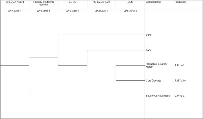
LOCA-MINOR event tree (without crediting moderator dumping)
Case B: Minor LOCA (Taking credit of moderator dumping)
On sensing loss of inventory from the reactor coolant/moderator system based on LOCA related conditions on quantum of loss of inventory and inventory loss rate, reactor and main coolant pumps trip automatically. Thereafter, the decay heat removal takes over the cooling function. However, there is uncertainty on how long it will be able to cater to cooling requirements as it depends on the severity of loss of inventory. The emergency core cooling system (ECCS) starts and works either to make up the lost inventory if the breach is relatively small or continue operating in closed loop and caters to core cooling. In case of inadequacy or uncertainty in operation of ECCS, there is a provision of light water injection into the core to cater to core cooling function. LOCA-Minor event tree is shown in Fig. 14. It can be observed from the figure that the contribution of LOCA-Minor event, considering the credit of BSS, towards CDF has come down to 7.11 × 10⁻¹¹/year from 2.44 × 10⁻⁸/year, which has been obtained without considering BSS in earlier section.
Fig. 14 
LOCA-MINOR event tree (crediting moderator dumping)
-
(a.2)
MAJOR-LOCA
Case A: major LOCA (not taking credit of moderator dumping)
As can be seen in case of major LOCA (Fig. 15), where credit is not given to the moderator dumping, the accident sequence of major LOCA with ECCS failure is the top contributor to CDF and the sequence of major LOCA with PSS failure is very close to the preceding sequence. That is why it is important to evaluate BSS from the point of qualification of this system for tripping the reactor in the event of PSS failure. Summing the contributions of both the sequences, CDF by major LOCA without taking credit of moderator dumping is estimated to be about 4.14 × 10⁻⁸/year.
Fig. 15 
Event tree for major LOCA (no credit for MDS)
Case B: major LOCA (taking credit of moderator dumping)
From the event tree of major LOCA with moderator dumping, as shown in Fig. 16, it can be observed that the event sequence of major LOCA with ECCS failure still remains the top contributor to CDF. Summing the contributions of all the event sequences, CDF by major LOCA with moderator dumping is estimated to be about 3.89 × 10⁻⁸/year, which is lesser than the value obtained without moderator dumping.
Fig. 16 
Event tree for major LOCA (taking credit for moderator dumping)
-
(a.1)
-
(b)
Deterministic analysis
We are now interested to carry out deterministic analysis to demonstrate the safety of the reactor with moderator dumping, which is simulated by tripping the reactor during a minor LOCA scenario. The analysis has been carried out only from core sub-criticality considerations. In case of minor LOCA (leak rate less than 1250 lpm), the reactor will be shut down safely, taking into account reactivity addition of 9 mk due to coolant voiding. Moderator dumping alone can bring the reactor to subcritical state with fuel, clad and coolant temperatures remaining within safe limits throughout.
For the case of major LOCA (leak rate more than 1250 lpm), moderator dumping is adequate to shut down the reactor safely with a shutdown margin of 10 mk subject to the condition that there is no bulk coolant void formation till the heavy water level in reactor vessel reduces by 85–90 cm, i.e. up to a period of 45–50 s from the initiation of LOCA. The reduction in moderator level in reactor vessel as function of time following dumping actuation has been taken from the observed data. However, if the failure is catastrophic in nature, the moderator dumping will not be adequate to shut down the reactor safely.
Loss of regulation incident (LORI) and flow coast-down analyses have been carried out assuming that the SORs fail to drop into the core and the reactor is tripped by heavy water dumping only. Loss of coolant analysis (LOCA) has also been carried out in the same manner but only to consider the core sub-criticality. Following are the conclusions:
-
(i)
In case of flow coast-down, the clad temperature exceeds the coolant saturation temperature for about 28 s. However, the Jens-Lott equation is not violated and no boiling takes place.
-
(ii)
LORI analysis shows that heavy water dumping alone is capable to trip the reactor safely without the temperatures reaching the safety limits.
-
(iii)
In case of LOCA, moderator dumping alone can bring the reactor to subcritical state with fuel, clad and coolant temperatures remaining within safe limits throughout. However, it has to be ensured that there is no bulk coolant void formation till the heavy water level in reactor vessel reduces by 85–90 cm, i.e. up to a period of 45–50 s from the initiation of LOCA.
-
(i)


4 Discussion
The LOOP stands out to be the major contributor to net CDF, which is estimated to be 1.47 × 10⁻⁴/year. This might be considered adequate for Dhruva as the target of 10−4/year (Basic Safety Principles for Nuclear Power Plants 1999) is considered acceptable for old plants. It may be noted that the target of 10−4/year is applicable for NPPs and it does not explicitly clarify whether this is a goal for CDF on limited scope PRA or full scope PRA. Limited scope PRA covers only the internal events and full power reactor operation whereas full scope PRA, apart from those covered by limited scope PRA, covers external events, low power and shutdown states of reactor and reactor pool and other radiation sources.
Dhruva is an Indian research reactor with very low enthalpy, pressure, temperature and core radioactivity inventory. Therefore, the probability of catastrophic failure is less as compared to an NPP where the system enthalpy is very high and the core inventory is also relatively large. However, the IAEA Safety Standard (Safety of Research Reactors 2016) clarifies that the research reactors with thermal power level more than tens of MW should be treated at par with an NPP. Further, in the aftermath of Fukushima accident, it is required to use the available safety margin to demonstrate the safety of the plant.
From the results of PRA, as shown in Table 4 and the deterministic studies involving neutronics and thermal hydraulics, following can be inferred:
-
(a)
LOOP: by giving credit to moderator dumping, the contribution of LOOP comes down significantly from 1.47 × 10⁻⁴/year to 6.83 × 10⁻⁶/year. The neutronic and thermal hydraulic analysis shows that moderator dumping even though relatively slow compared to gravity drop of shut-off rods, is adequate as the fuel and clad temperature remains well within limit.
-
(b)
LORI: the contribution to CDF from LORI comes down to 8.88 × 10⁻¹⁰/year from 2.44 × 10⁻⁷/year due to consideration of moderator dumping. Deterministically it has been shown that the fuel and clad temperature remains well within limit for LORI transient initiated from 1.0 KW power and terminated by the moderator dumping. Therefore, consideration of moderator dumping does not pose any challenge towards reactor safety.
-
(c)
LOCA: there are two situations that have been investigated, viz minor LOCA and major LOCA. In case of minor LOCA, the coolant system does not undergo phase transition for at least 30 min and deterministic analysis (crediting moderator dumping) shows that the fuel, clad, coolant temperature remains well within limit. Hence, consideration of moderator dumping for demonstrating the enhanced safety of the reactor is acceptable. However, the scenario of major LOCA, which involves catastrophic failure of coolant inlet loop and common structure, i.e. inlet plenum, is different from that of minor LOCA. Though Dhruva, being a low pressure and low temperature system, is not expected to fail in catastrophic manner (probability < 10−6/year), this needs to be evaluated probabilistically. The NUREG-800 (United States Nuclear Regulatory Commission 1987) stipulates that the maximum leak size for low pressure and low temperature system should be arrived at by considering dt/4 model. With this assumption, the catastrophic failure of the coolant system will be beyond design basis case. Hence, moderator dumping system can be considered as adequate for LOCA situation.
5 Conclusion
Looking at the contribution of three major initiating events to CDF without considering the moderator dumping system, it is felt necessary to evaluate the credit of the dumping system using the IRBE approach. Even if we consider that the CDF component from seismic and external flood and other events like air craft crash is insignificant due to topological features of the reactor, the contribution for low power and shutdown state may jack up the CDF to slightly more than the present estimate of 1.47 × 10⁻⁴/year. Given this background, it will be prudent to evaluate the CDF against available safety margin in the plant towards demonstrating the safety against deterministic criteria as well as probabilistic safety targets. Analysis shows that the consideration of available safety margin in terms of moderator dumping system improves the CDF by a factor of 10, which is quite significant. In order to investigate the implications of this consideration, deterministic analysis is carried out, where each initiating event is subjected to evaluation of limiting parameters, i.e. maximum fuel, clad and coolant temperature reached during the transients, etc.
References
A Brief History of Nuclear Accidents Worldwide (2018) http://www.ucsusa.org/nuclear-power/nuclear-power-accidents/history-nuclear-accidents. Accessed 31 Aug 2018
Agarwal SK, Karhadkar CG, Zope AK, Singh K (2006) Dhruva: main design features, operational experience and utilization. Nucl Eng Des 236(7):747–757
Applications of Probabilistic Safety Assessment (PSA) for Nuclear Power Plants (2002) Series: IAEA TECDOC Series, No. 1200. International Atomic Energy Agency, Vienna
Basic Safety Principles for Nuclear Power Plants (1999) 75-INSAG-3 Rev.1 (series: INSAG Series, No. 12, STI-PUB-1082). International Atomic Energy Agency, Vienna
Defence in Depth in Nuclear Safety (1996) Series: IAEA INSAG series, no. 10, STI/PUB/1013. International Atomic Energy Agency, Vienna
Deterministic Safety Analysis for Nuclear Power Plants (2010) Series: IAEA safety standard series, no. SSG-2, STI/PUB/1428. International Atomic Energy Agency, Vienna
FCOAST (1960) Adapted version of AECL code COASTDOWN developed by NRX staff
Hannaman GW, Spurgin AJ, Lukic YD (1984) Human cognitive reliability model for PRA analysis, Draft Report, NUS-5431, EPRI-2170-3. Electric Power Research Institute
Kinard M, Allen EJ (2004) Efficient numerical solution of the point kinetics equations in nuclear reactor dynamics. Ann Nucl Energy 31(9):1039–1051
Mazumdar T et al (2012) RITAC: reactivity initiated transient analysis code—an overview. Ann Nucl Energy 43:192–207
PRIS: Power Reactor Information System (2018) International Atomic Energy Agency. http://www.iaea.org/pris. Accessed 31 Aug 2018
Research Reactors (2018) World Nuclear Association. http://www.world-nuclear.org/information-library/non-power-nuclear-applications/radioisotopes-research/research-reactors.aspx. Accessed 31 Aug 2018
Safety of Research Reactors (2016) Series: IAEA safety standard series, no. SSR-3, STI/PUB/1751. International Atomic Energy Agency, Vienna
Singh T et al (2013) Development of neutronics and thermal hydraulics coupled code—SAC-RIT for plate type fuel and its application to reactivity initiated transient analysis. Ann Nucl Energy 62:61–80
Swain AD, Guttman HE (1983) Handbook of human reliability analysis with emphasis on Nuclear Power Plant Applications. NUREG/CR-1278, United States Nuclear Regulatory Commission
United States Atomic Energy Commission (1975) Reactor safety study: an assessment of accident risks in U.S. Commercial Nuclear Power Plant: Executive summary: Main report. WASH-1400-MR, United States Atomic Energy Commission
United States Nuclear Regulatory Commission (1987) Standard review plan for the review of safety analysis reports for nuclear power plants, NUREG-0800, United States Nuclear Regulatory Commission
United States Nuclear Regulatory Commission (1995) Use of probabilistic risk assessment methods in nuclear regulatory activities; final policy statement (60 FR 42622) 1995. https://www.nrc.gov/reading-rm/doc-collections/commission/policy/60fr42622.pdf. Accessed 18 Sep 2017
United States Nuclear Regulatory Commission (2000) Technical basis and implementation guidelines for A Technique for Human Reliability Analysis (ATHENA). NUREG/CR-1624, United States Nuclear Regulatory Commission
Author information
Authors and Affiliations
Corresponding author
Rights and permissions
About this article

Cite this article
Varde, P.V., Singh, T., Mazumdar, T. et al. Risk-based approach towards design evaluation and re-assessment of shutdown safety margin. Life Cycle Reliab Saf Eng 7, 215–234 (2018). https://doi.org/10.1007/s41872-018-0047-7
Received:
Accepted:
Published:
Issue Date:
DOI: https://doi.org/10.1007/s41872-018-0047-7