
Abstract
This article focuses on evaluation of in-service power transformerphysical health condition using Health Index (HI) approach. The Health Index (HI) approach is applied by incorporating three key stages such as input for health index assessment, health index estimation and output health index for maintenance decision process of each transformer unit. The first stage is based on condition index, and importance index assessment and also through applying scoring and weight scheme for each test parameter. The condition index of a specific power transformer is evaluated by twelve different diagnostic tests and importance index is assessed from five different factors such as age, loading history, maintenance records, failure/faults, and its location, etc. Numerical weighting and scoring factors were assigned for every test/factor to determine the actual condition of the power transformers with regard to condition and importance aspects. In second stage, By combining the condition and importance index assessment evaluation, the numerical value called Health Index (HI) was estimated, which represent the overall health of a power transformer asset. In third stage, health index estimation results were used to plan for effective maintenance tasks. Through this approach, a case study was performed for 21 in-service power transformers belonging to Tamil Nadu electric utility. The HI results of 21 transformer units were ranked and classified into poor/failed, fair and good, which were further facilitated for Inspection, Repair, and Replacement (IRR) maintenance decisions. Thus, the study is very useful to utility maintenance engineers for better understanding the transformer physical health condition and required maintenance actions timely, which prevents unexpected failure and also reduce cost of maintenance in electric utilities.
1 Introduction
Power transformers are one of the major asset that represent a considerable investment in any electrical power system network (Abu-Elanien et al 2011; Murugan and Ramasamy 2015). The reliable operation of power systems crucially depends on the condition of working transformers (Chafai et al 2016). Phenomenal events, such as, daily rise in excess voltages, crisis loading, high operating temperature, switching faults, short circuit in systems, lightning impulses, deprivation of oil and paper insulation, and humidity can affect the in-service power transformers (Arshad et al 2014). The above said factors are continuously subjected to electrical, mechanical, thermal, chemical and environmental time variable stresses resulting in failure risk of power transformers (Liao et al 2011; Wang et al 2002). If the operational degradation or risk of failure cannot be detected in time, leading to partial/complete damage of transformers or the catastrophic failure will take place (CIGRE Working Group A2, 34. 2011; Tang. 2014; Sefidgaran et al. 2011; Jahromi et al. 2009). The failure of which can effect in a major distress on power system. Outage of large transformers can be disastrous in many of the cases and result in direct and indirect cost to both customers and electric utilities. Further, repair and replacement of damaged components may take longer time (Murugan and Ramasamy 2019; Zhou et al 2014). Therefore, there is an increasing demand in electric utilities to assess the actual health condition of transformer with new asset maintenance approach is essential in recent years.
Maintenance is a key aspect of asset management. The purpose of maintenance activity is to extend asset operational lifetime and/or reduce the likelihood of its failure. Maintenance approaches can be classified into three main categories: corrective maintenance (CM), preventive maintenance (PM) and reliability centred maintenance (RCM) The corrective maintenance (CM) also known as breakdown maintenance, which is performed when the equipment fails and, during the breakdown. The most common form of CM is minimal repair only. The preventive maintenance (PM) aims to prevent the failure from occurrence and ensure a long lifetime of the equipment condition. PM is achieved by taking outage of the equipment or online condition monitoring regularly. Preventive maintenance approaches may be further classified into several types: time-based maintenance (TBM), and condition based maintenance (CBM). TBM is performed at regularly scheduled time intervals regardless of the equipment’s condition based on either the guidance of the equipment’s manufacturer or instructions framed by the electric utilities. CBM is performed according to the actual health condition of the equipment using either offline or online through the use of various condition tests, oil sampling and other methods. Reliability centred maintenance (RCM) is performed based on component failure modes and their effects only (Abu elanien & Salma 2010).Among various approaches, the Health Index (HI) approach has emerged as a valuable method for the assessment of a power transformer and it is very useful for representing the overall health condition of working transformer (Jahromi et al 2009). Further, it is based on various condition criteria which quantifies equipment current condition related to the long-standing degradation factors accumulatively, which includes an indication of the high risk of failure or rapid deterioration and that have reached their operational or age wise end of useful life level (Abu-Elanien et al 2011). With this information, electric utilities can decide maintenance actions such as Inspection, Repair, and Replacement (IRR). Further, this information enables the utilities to identify which transformers need immediate expenditures such as repair or replacement, which will require maintenances in the near future but not immediately, and which are in good condition and do not need any immediate action. The HI can also be useful for planning routine maintenance strategies for transformers viewing signs of rapid deterioration. Therefore, HI is a powerful tool for asset management planning of working transformers.
The study in the area of health index based asset management of power transformers is a factually new approach and few correlated papers have been published. Therefore, more exploration is necessary for the HI approach, so that the electric utilities can experience the full benefits of this approach. Abu-Elanien et al. (2010) briefly discussed the transformer asset management under condition assessment using advanced techniques (CA), online condition monitoring (CM), performing various maintenance plans, and end-of-life assessment. Jahromi et al. (2009) explained the health index, is a single index factor using liner relationship between various tests which combines operating observations, laboratory tests and field inspections to aid asset management. Abu-Elanien et al (2011) performed, a transformer health assessment using a feed forward artificial neural network (FFANN). Velasquez-Contrerasa et al. (2011) were conducted a general asset management model using condition and risk assessment for power transformers. Abu-Elanien et al (2012); Zeinoddini et al. (2016) presented an approach for calculating a health index based techno-economical transformers life assessment for under 69 kV only by using fuzzy set theory. Jahromi et al (2013) discussed a two-stage framework model for power transformer asset maintenance management. This model optimizes midterm and short-term maintenance. Murugan and Ramasamy (2015) used a general approach to calculate a health index based on condition parameters of power transformers. Pompili and Scatiggio (2015) performed health index based Iso attention classes for power transformer maintenance. Trappey et al (2015) carried out intelligent engineering asset management system for power transformer maintenance using genetic component based approach. Ahmed et al (2015) were used wavelet networks to find transformer HI. Zeinoddini et al. (2016) performed HI calculation using technical and economical parameters with Artificial neural networks, in which no major insights are presented. Islam et al (2017) performed a general regression neural network based health index calculation of power transformers. There are no maintenance actions were suggested. Tee et al (2017) presented a general ranking approach for insulation condition assessment of transformers, but HI approach was not used. Azmi et al (2017) performed transformer health index in the form of mathematical equation. Fernandez et al. (2017) done HI calculation considering winding hot spot temperature and load index of a transformer. Singh A and Swanson AG (2018) developed a plant health and risk index for distribution power transformers in south Africa. Islam et al (2018) presented health index calculation using GRNN approach for few subsystem of power transformers. Jaiswal GC and Suryawanshi HM (2018) presented genetic algorithm based health index determination of distribution transformers. Alqudsi A and El-Hag A (2018) presented an artificially based insulation HI with a relatively smaller number of input test features. Benhmed et al (2018) were used the most influential testing parameters such as water content, acidity, breakdown voltage, and furan, in determining the transformer HI. Foros J and Istad M (2019) presented health index calculation using condition model. Aizpurua JI et al. (2019) have developed a soft computing based health index approach under uncertainty. Only three uncertainties such as DGA, oil and paper insulation were used for health index formulation. Murugan R and Ramasamy R (2019) presented condition based health index considering various condition tests. Abu-Elanien et al. (2019) performed evaluation of transformer health condition using reduced number of tests. Zhou L and Hu T (2020) presented multifactorial condition assessment for power transformers. Li S and Wu G (2020) have developed a probabilistic health index based apparent age estimation for power transformers. Test results were just compared each other but no maintenance plans were suggested. In summary, various articles have been published with the concept of HI based decision and strategies to the electric utilities, however, HI based inspection, repair and replacement maintenance tasks for in-service power transformer has not been presented in the literature before along with wide-ranging details and assessment procedures.
In this paper, evaluation of in-service power transformer physical health condition for maintenance planning is presented. The study is performed using Health Index (HI) approach by incorporating three key stages. The first stage is based on condition index, and importance index assessment and also through applying scoring and weight scheme for each test parameter. For condition index assessment, twelve diagnostic tests such as Dissolved gas analysis (DGA), CO2/CO Ratio test, break down voltage test (BDV), interfacial tension (IFT), power factor (PF) test, frequency domain spectroscopy (FDS), turn ratio (TR), winding resistance (WR), polarization index (PI), core resistance (CR), sweep frequency response analysis (SFRA) and short circuit impedance (SCI) were used. Similarly, importance index assessment was performed from, five important operational related factors such as age, loading history, maintenance records, failure/faults, and its location. Numerical weighting and scoring factors were assigned for every test/factor to determine the actual condition of the power transformers with regard to condition and importance aspects. In, second stage, by combining the condition and importance criteria, Health index (HI) for a transformer is estimated using liner mathematical equation. In third stage, health index estimation results were used to plan for effective maintenance tasks such as inspection, repair and replacement. Subsequently, the proposed methodology is verified through a case study by analysing 21 power transformers belonging to a Tamil Nadu electricity company.
This structure of the paper is as follows; Sect. 2 discusses the proposed health index approach for power transformer which includes a detailed description of input for health index, health index estimation and output health index for maintenance decision. In Sect. 3, a case study is presented for validation of the proposed methodology. Section 4 deals the results and discussion. Finally, concludes the paper in Sect. 5.
2 Proposed methodology
Fig. 1 depicts the proposed Health Index (HI) approach for power transformer. The proposed approach is divided into three main subsections which are, input for health index (Condition Index (CI) assessment; Importance Index (II) assessment, and score and weight scheme for ranking), health index estimation using liner mathematical equation and output health index. Initially, the process starts from the filed data collection step by listing all the available datasets (condition diagnostic test data and importance factor data) for in-service power transformer. Subsequently, in each test result, score and weight values are applied to find the condition and importance index for each transformer unit. The transformer current condition and its operational impacts are usually evaluated separately. Current condition of a transformer subsystems was assessed by applying various diagnostic tests and its overall total weightage is considered about 70%. which represented the condition index (CI) assessment. The operational impacts of a transformer unit were assessed with various factors and its overall total weightage is considered about 30%, which represented as the importance index (II) assessment of a transformer unit. Followed by, by combining condition and importance index results are converted into a normalized health index, which indicates the overall physical health condition of a transformer. Finally, health index estimation results used for maintenance decision process along with suitable maintenance actions. Note that available dataset of each transformer subsystems are dependent on the specific condition/importance assessment strategy of each company. The proposed HI approach is detailed in the following sub-sections.

The proposed Health Index approach for power transformer
2.1 Input for health index
The input for health index is obtained from condition index (CI) assessment, importance index (II) assessment, and also through applying score and weight scheme for every condition and important test parameter, which has been discussed in subsequent section.
2.1.1 Score/Weight technique for ranking
Every condition index (CI) and importance index (II) test results need to be assessed by applying a numerical scoring/weighting factor. In this article, considering the electric utility requirement, authors developed, a numerical score and weight value for every condition test /importance factor, in order to rank the power transformer current health condition in terms of percentage, which has been discussed as follows. Score technique for ranking: The score levels are determined by referring to IEEE, IEC, and CIGRE standards, literature, and practical experience (Murugan and Ramasamy 2015). The applied score depends on the assessment of the testing results of each test parameter. The score for each test parameter is expressed in Sci (condition index score) and Sii (importance index score). It represents in the form of numerical number for each test according to the testing standards. This practice relays on evaluating each test individually for condition index and importance factor assessment. For each transformer, each test will be given a score from 1 to 3. If the health of the working transformer with respect to test result is normal condition, a score of 3 will be specified to that test for this particular transformer, while a score of 1 will be fixed to the test whether the health of the working transformer with respect to that test result is poor condition. If the health of the working transformer with respect to test result is in suspect condition, a score of 2 will be given to the test according to its evaluation. Condition index assessment (CI) use twelve test parameters. Each test parameter maximum score is 3. Therefore, the normalized maximum condition index (Smaxci) test score is 36. Similarly, a quantitative evaluation scoring scheme is also assigned to each importance factor. Importance index (II) assessment use five factors. Each factor maximum score is 3. Therefore, the normalized maximum importance index (Smaxii) test score is 15. Score values for each condition index and importance index parameter are given in Table 2 and Table 4 respectively. Weight technique for ranking: The weight grade technique is applied for ranking in terms of a greater or lesser degree of importance of each test that deviate the actual condition and importance of a power transformer. Transformer experts / working experience requires assigning the weight grade for every condition test parameter and importance index factor assessment. The weight grade for each test parameter is expressed in Wci (weight grade for each condition test) and Wii (weight grade for each importance index). The weight grade for each test can be varied on the basis of the current practice of an electric company. The applied weightage grade systems are categorized into several levels based on the deviation that ranges from one to five: The grade which start with Weight ‘1’ for very low importance, Weight ‘2’ for low importance, Weight ‘3’ for moderate importance, Weight ‘4’ for high importance, Weight ‘5’ for very high importance (Murugan and Ramasamy 2015). The test that has the highest importance, with respect to evaluating the transformer health condition, takes an index of five. The higher weighting system, shows that greater contribution to asset degradation. The test that has the lowest importance takes an index of one.
The applied scoring grade for every test criterion is normally multiplied by its a weighting grade, then the overall condition of the transformer under investigation is evaluated. See the Table 2 projected weighting and scoring grades for every condition diagnosis test parameter. Similarly, the applied scoring grade for every importance criterion is multiplied by its a weighting grade, then the overall impact of the power transformer under investigation is evaluated. The projected scoring and weighting grades for every importance parameter are given in Table 4.
2.1.2 Condition Index assessment (CI)
Condition index (CI) is a numerical value reflecting the actual condition or probable risk of failure of each power transformer. The transformer major subsystems and its condition test techniques are shown in Fig. 2. In the current work there are five transformer components prone to increasing the in-service failures namely (1) Winding, (2) Core, 3. Bushing, (4) Tap changer and (5) Oil and paper insulation due to its continues operation. All these components can be assessed by condition assessment test techniques. To estimate a condition index (CI), twelve representatives test parameters were used. The input test parameters to CI assessment is normally collected from field testing, working observations, laboratory test works and any other relevant knowledge and information. Each condition test parameters and its most important features are given in Table 1. With above twelve condition test criteria, quantification of condition index is formulated. See the Table 2, all these test parameter criteria, a quantitative numerical evaluation scoring and weighting factors are assigned. The final value of the transformer condition index was obtained by multiplying the weight of each condition test parameter (Wci) with condition index score (Sci) and divided by the maximum score of the condition with weight of each condition test parameter (Wci), then multiplied by one hundred. So, that at the end, one single “condition index” (CI) can be calculated using Eq. 1 and expressed in terms of percentage. Figure 3 is shown the typical condition index assessment. The condition index criterion for power transformer assessment is given in Table 3. Further, the condition level is pictorially represented by means of traffic light color scheme.
where
Sci Score of each condition test criteria corresponding to parameter “ci”
Smaxci Maximum score of each condition test criteria corresponding to parameter “ci”
Wci Weighting factor for each condition test criteria corresponding to parameter “ci”
nNumber of diagnostic tests considered for calculation of the condition index
70% of weightage factor represent the CI assessment of a transformer

Power transformer major subsystems and their condition test techniques

CI assessment for in-service power transformer
2.1.3 Importance Index (II) assessment
The importance index (II) is a numerical value reflecting the consequence of potential failure of power transformer in the electric network. It is considered the power transformer and its network service related historic experience owned by the electric utility. In the present work, five criteria in consultation with various transformer experts that can be designated as importance evaluation factors for power transformers which is shown Fig.4. Further, each importance index parameter limit levels, scoring and weighting factors for computation of importance index is given in Table 4. Further, it has been discussed as follows. Age Transformer age is considered as one of the important factors of power transformer in electric utilities. The age of power transformer is defined as the number of years in service since from the installation date. The age wise transformer failure was considered based on the bath curve representation in three levels. Loading history It refers to the historical peak load/overloaded during the customer requirement and their climatic conditions in electric utilities. Extended periods of overload with an excessive ambient or partial cooling may result in sustained temperature resulting degrade the insulation. Based on operating standard, the power transformer load should not exceed 80% of its rated capacity. The loading factor of a power transformer is given in terms of percentage against its rated capacity. In this study, only 32 MVA capacity have been considered. Maintenance records It refers to the number of inspections/maintenance schedules reported in an established period of time in electric utilities. Failing to perform the inspection and maintenance of power transformer within its planned time schedule may lead to failure of the transformer. This factor is considered to be very important. Therefore, the high weightage factor is assigned. The ranking factor is given in terms of months. Fault/Failure history Refers to the average number of time failures/faults reported on the transformer in an established year. Exposure to system faults and frequent switching operations resulting in degradation of the transformer performances and therefore shorten its operational lifetime. The ranking on this factor is based on the number of times failures/faults occur within the scheduled period as 0–2 times, 3–5 times or more than 5 times in its life cycle. Location Transformer location influences the level of exposure to various power system faults, and frequent switching operation. This will lead to thermal and mechanical degradation of the transformers.

Various factors for importance index assessment of power transformer
With above five criteria, quantification of importance index is formulated. For all these criteria, a quantitative numerical evaluation scoring and weighting factors are assigned. So that at the end, one single “importance index” (II) can be calculated using Eq. 2 and expressed in terms of percentage. Figure 5 is shown the importance factors and their corresponding scoring, weighting factor that are applied in this study for importance index assessment of power transformers. The criterion for importance index assessment of a power transformer is given in Table 5. Further, the assigned importance is pictorially represented by means of traffic light color scheme.
where

II assessment for in- service power transformer
Sii Score of each impotence index criteria corresponding to parameter “i”.
Smaxii Maximum score of each impotence index criteria corresponding to parameter “i”
Wii Weighting factor for each importance index criteria corresponding to parameter “i”
nNumber of impotence criteria considered for calculation of the importance index
30% of weightage factor represent the II assessment of a transformer unit.
2.2 Estimation of health index (HI)
In this study, relating the condition and the importance index calculation using Eqs. (1) and (2), the physical health condition of the power transformer was estimated, which is called “Health Index (HI)”. The HI is estimated by considering a linear relationship between all inputs. The HI can also be represented by the following Eq. 3:
where HI is health index represent the overall physical health condition of a power transformer asset.
The general health index is standardized to a maximum health condition criterion 100 and 0 for the lowest health condition criterion, where the of value of the HI is100%, indicates “good” health condition and the value of less than 40% indicates “poor” health condition of a power transformer.
2.3 Output of health index for maintenance decision
The output of the health index (HI) is subjected to a certain range where the maintenance decision will be taken accordingly. By considering electric utility guidelines, literature guidelines, transformer expert experience and also the health index results, an appropriate interval/ maintenance tasks are defined. Table 6 offers, some selected HI range for each health index level, which indicates the transformer current physical condition and its required maintenance actions. Further, HI results are grouped into three level, indicating the health condition of the transformer as poor/failed, fair and good. Subsequently, three steps of maintenance tasks are planned for power transformers against each class of health condition level, which are pictorially represented by means of traffic light color scheme.
3 Case study evaluation
A case study was performed for 21 in-service power transformers belonging to a Tamil Nadu electric utility in order to apply the proposed approach and its procedure to calculate Health Index (HI). The key procedural aspect of every power transformer under study are named as PT1, PT2…up to PT21 numbers with rating of 110/11 kV, 32 MVA capacity for a 35-year life expectancy. All the selected transformer key data is given in Table 7.
3.1 Condition index evaluation
The condition of 21 power transformers PT1, PT2, PT3, PT4 … and PT21 with rating of 110/11 kV, 32 MVA are evaluated by the recommended measurement test techniques from Table 1. The tests were used such as DGA, CO2/CO ratio test, IFT, BDV, PF, FDS, TR, WR, CI, PI, SCI and SFRA. Based on the criterion given in Table 3, numerical score and weight scheme for every test were applied, then the condition index of transformer was calculated using the Eq. 1. As a case study sample for the condition index calculation, power transformer ‘PT3’ with rating 110/11 kV, 32 MVA was performed. This involves grouping together the several condition test techniques, making the liner logical preparations and applying scoring and weighting techniques of all the test parameters to permit combining them into a condition index. For example, for transformer PT3, the test includes DGA, CO2/CO ratio test, IFT, BDV, PF, FDS, TR, WR, CI, PI, SCI and SFRA were performed respectively. The CI evaluation results of ‘PT3’ power transformer were given in Table 8. It indicates that the condition index is equal to 66%, which indicates good physical health condition level. Suppose, CI indicates low health condition, which is most doubtful and requires careful intent. By applying the same procedure, the condition index of remaining 20 power transformers PT1, PT2, PT3, PT4, PT6… and PT21 were detailed.
3.2 Importance Index Evaluation.
The importance index of 21 power transformers includes PT1, PT2, PT3, PT4, PT5… and PT21 with rating 110/11 kV, 32 MVA were assessed. Operational factors such as age, loading factor, maintenance records, faults/failures, and location of the transformer were considered for importance assessment. Based on the criterion given in Table 5, numerical score and weight scheme were applied for every factor, then the importance index (%II) of each transformer was calculated using the Eq. 2. As a case sample for the importance calculation, power transformer ‘PT3’ was detailed here because of its good importance index level. This involves grouping together the several importance factors, making the liner logical preparations and beginning the importance scoring and weighting techniques of all the parameters to permit combining them into an importance index. For example, for transformer PT3, the test includes age, loading factor, maintenance records, faults/failures, and location were performed respectively. Therefore, according to The II assessment results of ‘PT3’ power transformer was given in Table 9. By applying the same procedure, the importance index of other 20 power transformers PT1, PT2, PT4, PT6… and PT21 were detailed.
3.3 Health index (HI) output for maintenance decision
The results of HI are useful for ranking and maintenance planning of transformer units. But it is vital to classify what type of ranking the health index is to be used. Therefore, HI range was selected from 0 to 100 points as numerical values in order to determine the current operating level of the transformer. These operating level was directed toward a comparative ranking based on current health condition levels like good (76–100), fair (41–75), and poor (0–40) as per Table 6, which is further useful to maintain the tasks as inspection, repair and replacement, respectively. By applying HI approach, 21 working transformers are assessed. The final HI results, which highlight the power transformer in-service deficiencies and defects that requires maintenance in order to extend asset operational lifetime. HI results of 21 transformers are shown in Table 10. As part of case study, nine power transformers namely PT3, PT7, PT11, PT14, PT15, PT16, PT17, PT20 and PT21 with higher HI value indicate with good physical health condition, eight transformers namely PT1, PT4, PT6, PT9, PT12, PT13, PT18, and PT19 with moderate HI value, indicate fair physical health condition and four transformers namely PT2, PT5, PT8, and PT10 with lower HI value, indicate poor physical health condition level.
The results confirm that the transformer with a lower physical health condition have higher risk of failure, which are needs to be first focused on maintenance planning in terms of three steps namely Inspections, Repair, and Replacements (IRR) according to the health index value of each asset unit. From Table 10, the correlation between health indices with respect to every transformer unit can be visualized as health index histogram which is shown in Fig. 6. The HI level of each assessed transformers were represented with color indicators as follows: ‘G’ stands for green/good health, ‘Y’ stands for yellow/medium health and ‘R’ stand for red/lower physical health condition. Further, each maintenance tasks should be considered as a specific case, which has further been interpreted as follows:

Health index histogram
3.3.1 Inspections
The HI score of power transformers comprising PT3, PT7, PT11, PT14, PT15, PT16, PT17, PT20 and PT21 (110/11 kV, 32MVA) were in the range of 76 to 100%, which represent the transformers in “good health condition level”. Therefore, inspections are recommended as part of maintenance tasks, unless it attains the failure limit. Inspections denote the visual inspection which is conducted on all of utility power transformers on a scheduled basis followed by frequent condition diagnosis testing. The defects found are reported and then scheduled for the repairs based on their severity. In most cases, inspection will not require an outage and can be performed while the transformer is in operation. A summary of visual inspection and maintenance condition digenetic test intervals are given in Table 11.
Visual inspection comprises Daily/monthly/six month Inspection of physical condition, HV/LV bushing porcelain, surfaces and sealing condition, Oil level, Oil leakage, tank gaskets, valves, breather, oil temperature, winding temperature, grounding of main tank, abnormal sound, alarm trip contacts of buchholz relay, trip contact of pressure relief device, alarm contact of oil level indicator, On-Load Tap Changer mechanism, radiators, coolers, local, remote, automatic cooling control, fan operations; Insulation Condition Dissolved Gas Analysis (DGA) test, furan concentration, degree of polymerization value, interfacial tension and the ratio of CO2/CO test; Oil Quality analysis Moisture concentration, breakdown voltage, polarisation index, Power factor of oil, water concentration and capacitance measurement; Internal Components Electrical test includes insulation resistance, Core insulation resistance turn ratio, winding resistance, short circuit impedance and excitation current; Bushing Condition capacitance measurement and power factor measurement; Tap Changer Condition Check operations per month, and contact resistance; Advanced electrical tests advanced tests including Frequency response analysis (FRA), Polarization/depolarization Current (PDC), Frequency domain spectroscopy (FDS), Return voltage measurement (RVM), and UHF detection of Partial discharge (PD. These aforesaid condition tests should detect problems such as winding and core deformation, overheating, hot spots, partial discharge, and arcing, moisture in oil-paper insulation and insulation aging degradation.
3.3.2 Repair/refurbish (Midlife)
The HI score of power transformers comprising PT1, PT4, PT6, PT9, PT12, PT13, PT18, and PT19 (110/11 kV, 32 MVA) were in the level of 41–75%, that represent the power transformers in “fair health condition level”. Therefore, repair or refurbishments are recommended as part of maintenance tasks, only when the apparatuses are repairable. Normally, refurbish/repair of transformers involve complex operations. They require a group of transformer specialist. For better understanding, the transformer repair process, includes the following steps:
-
The repair/refurbish work commenced with either on site in the substation or in a transformer factory for failure diagnostic. Undertaking a major repair or upgrades activities in factories/workshops are required some important condition such as good housekeeping, orderliness, and well controlled atmosphere. On site repairing transformers usually permits them to return back in service in a shorter period of time and also reduce the risks and cost associated with heavy transport. Further, it needs to be equipped with special tools, spare parts, heavy lifting equipment, highly skilled experts and testing facilities. In-service failed power transformer is normally brought to transformer repair bay/workshop, where disassembled, then access to core, winding, bushing, tap changer and perform fault tracing for repair/refurbish purpose, which has been discussed below.
-
Winding fault tracing: In this example, due to an external short circuit, network overloading or high inrush currents, winding deformations in the clamping structure can take place, which at the same time will lead to axial and radial forces that might fatigue the solid insulation between turns/discs. In order to assess such failures, the sweep frequency response analysis (SFRA) and short circuit impedance (SCI) techniques are used as part of the fault tracing in winding.
-
Core fault tracing: The laminated structures of the core can allow sufficient eddy current to flow, which cause serious overheating due to loss of core lamination, core bolt fails, debris in contact with core and deteriorated core lamination. The effects of the local overheating initiate the core insulation defective, which turn to damage the winding. As time goes in an oil immersed transformer, by the effect of local overheating sufficient to cause winding insulation damage, which will help even oil degradation with an accompanying evolution of gas. This gas will spurt to the conservator and could cause the trip of the buchholz relay. The sweep frequency response analysis (SFRA) and core insulation resistance (CI) measurements are used as part of the fault tracing in core.
-
Oil/Paper Insulation fault tracing: Transformer insulation oil is subjected to degrading during its continuous operation. The main factors for oil degradation are moisture, high working temperature, oxygen (oxidation), oil impurities, effects of electric field and catalyst action. Temperature and oxidation play a dominant role in oil degradation routes. Physicochemical properties release of organic acids, which led to the formation of alcohols, phenols and simple esters. Then, these products are dissolved into the insulating oil. As a result of continuous oil oxidation, oil-insoluble deposit will take place such as asphalt, tar, soap precipitate and sludge sedimentation, which has a strong acidic reaction and extensively accelerate the paper (solid-cellulose) degradation. Under these circumstances, insoluble deposits will also occur on the surface of the winding, core, tank and radiators, that limit the heat dissipation capacity, which further accelerating the degradation process of the paper insulation. Moisture is another factor for the paper insulation degradation process. The solid insulation ageing process is five times faster with 3 % moisture content in the insulation. Moisture also causes various problems, such as the bubbling effect which reduces the current carrying capacity of the internal unit. For the best maintenance of the transformer oil/paper insulation, it is advisable making a periodical test on the oil. If the transformer works on continuous service, every two years it is advisable to take off a sample of oil from the tap at the bottom of the tank and carry out a dielectric test. If the test gives an insufficient result and indicated the oil is pink coloured, it means that a suitable drying treatment into an oven is necessary until they go back to their original blue. Drying of transformers can normally be achieved by off-line techniques. There are two major drying process of oilpaper insulation, which are: vacuum drying techniques and low frequency heating. The conventional drying process is carried out by vacuum cum hot oil circulation approach. It consists of oil heater, a streamline filter cum vacuum chamber machine etc. Normally the drying process in two levels. The first level applies vacuum drying and the second level applies hot oil circulation. Initially, connect the vacuum pump and applying a vacuum of 0.75 torr or less at ambient temperature for 24 hours. Simultaneously, the oil was dried, degassed and filtered separately. This was followed by fill the tank with filtered oil from the top of the unit and circulates the hot oil at no more than 80°C and should be circulated to maintain an exit temperature of 60°C. Finally, when the temperature of inside tank is 30 to 40-degree C, the hot oil circulation will be finished. Oil insulation samples were collected before and after the process in order to compare the drying effect. Low frequency current heating (LFH): In order to heat up both high and low voltage windings, LFH is applied in combination with hot oil spray to the transformer with a frequency of 1 Hz. The LFH is heating the windings from the inside whereas the hot oil spray helps the heating process of the insulation outer parts. This LFH approach ensures the whole transformer can be heated very uniformly, reduce the drying time, lower moisture content and achieve high-quality insulation of the transformer. A good oil treatment unit should always be able to achieve, residual gas concentration approx. 0.04% and electric strength higher than 60 kV. After drying out, the core clamps need to be tightened up to ensure the active parts are adequately clamped.
-
Bushing fault tracing: 90% of bushing foil degraded by moisture ingress, cracks, change of capacitance value etc. Bushing porcelain surface is cleaned and examined them for cracks, and oil leaks especially when bushings are exposed to polluted atmosphere condition. Also check the oil level if the bushing is provided with a hole on the upper metallic part. Normally, slight chips may be overlooked but any serious damage will require replacing with new porcelain. Often the in-service bushing flange is the one leaking culprit. In order to arrest such leak, clamps are usually fabricated from cast aluminium, which contain the sealing compound under pressure and stop the leak over the leaking bushing flange. Consequently, dielectric loss measurement (tg δ) test need to be performed every 5 years, according to IEC recommendation. At any rate it is advisable to be provided at least with one spare bushing, mostly because models change and are not always interchangeable.
-
Tap changer fault tracing: Tap changer is one of the vital part of transformer. There are three groups of tap changer failures that include insulation (oilfilm layer deposition, weakening of insulation characteristics); mechanical (coking of contacts, arcing contact wear, deviations in switching times, contact timing issues, maintenance errors, damaged transition resistor and motor drive mechanism.) and electrical (electrical treeing, synchronization switches, arcing currents). In order to identify such failures, dynamic resistance measurement (DRM) technique is used as part of fault tracing in tap changer.
-
Accessories: Transformer is equipped with accessories (oil and winding temperature indicator, pressure relief device, oil level indicator, bladder, silicagel breather, current transformers, etc.). For all transformer accessories, it is recommended to be tested yearly. Two fault tracing cases are discussed below.
-
Case 1: A fault involving the transformer itself is usually signalled by the buchholz relay, before or at the same time as the current differential or over current protection operation. The Buchholz relay can cause the transformer to be switched out in case of a local overheating, or partial discharges occur within the tank, resultant large quantities of gas rise to the top of the tank. These rapid internal pressure rise through the pipe between the tank and the conservator then enter into Buchholz relay, but it also emits an alarm signal when there is a fault with slow production of gas. Fig. 7 shown the sequence of checks and operations to carry out, and the measures to be taken if the relay operate. Firstly, check the gases collected, then take a sample for analysis while the transformer is kept out of service, or find causes of the problem before returning it to service.
Fig. 7 
Fault tracing for buchholz trip operates
-
Case 2: Oil Temperature Indicator(OTI)/Winding Oil Temperature(WTI): Overload causes winding and oil temperature rise in a working transformer. Overload can be carried for limited periods and recommendations for oil immersed transformer are given as per IEC 60354. Oil temperature of about 95°C and winding temperature of about 113°C are considered to be the maximum working temperature. The value beyond which a further rise of 8°C-10°C continuously, will halve the insulation life of the unit. Therefore, transformer overload protection is performed based on oil & winding temperature measurement by thermostat with both alarm and/or trip contacts. Fig. 8 shown the sequence functioning of the OTI/WTI instrument for 40 MVA transformer. Firstly, check the setting and its operation of OTI/WTI alarm /trip for 40 MVA transformer. In case of overload fault at OTI-95°C /WTI-113°C gives warning alarm first subsequently at OTI- 110°C /WTI-135°C trip will take place. In order to maintain normal working conditions, reduce overloading, maintain in service cooling and also ensure that the oil and winding temperature does not rise above the prescribed limit. Else recondition the oil and repair transformer winding timely.
Fig. 8 
Fault tracing for OTI/WTI alarm/trip operates
-
Finally, the external surface of the tank, and coolers are cleaned and prepared for dielectric tests according to the agreed test plan.


3.3.3 Replacement (End of life)
The HI score of power transformers comprising PT2, PT5, PT8, and PT10 (110/11 kV, 32 MVA) were in the level of 0 to 40%, that represent the transformer in lower physical health condition level. Therefore, replacement is suggested as part of recommended maintenance plans, suppose if the apparatus condition is not overhauled or ending its operative life/physical condition of a transformer. The replacement should be performed either transformer component wise or as complete part based on five main stages, which are discussed as follows as:
-
Data Collection Phase
The first phase of the replacement process is to collect the data for the existing (critical) transformers. This data includes the capital cost (CC) of the transformer, annual cost of operation(ACO), annual cost of failure(ACF), annual cost of repair(ACR). All of these data are normally used to estimate the transformer’s present worth, annual cost phase and equivalent annual cost.
-
Calculation of the transformer present worth value (PWV)
The second phase involves the estimation of the present worth for the transformers useful lifetime of existing transformer. A transformer’s present worth is estimated using depreciation method. The depreciation model is divided into three phases based on failure rate such as constant or no failure (infant), constant failure rate (normal), and increasing failure rate (wear out) phase. Infant and normal phase are showed as straight line, because the failure rate is constant and also less depreciation of the transformer in this stage. But, sudden failure may happen due to operational issues. In the wear-out stage, the depreciation of the transformer increases due to wear and tear. The depreciation model for in-service transformer is shown in Fig. 9. With these, the depreciation cost is normally decided in case of failure of transformer from any of one the operational phase per annum basis. Finally, the present worth of the transformer can be calculated according to the following formula.
PWV = Capital cost of the transformer (CC) – (Depreciation cost from the failure phase) / annum basis.
Where PWV—Present worth value of the transformer at the end of year, CC—Capital cost of the transformer.
Fig. 9 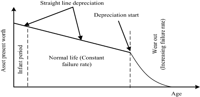
Depreciation model for in-service transformer
-
Calculation of the Annual Costs phase (ACP).
The purpose of third phase is to estimate the annual cost of operation(ACO), annual cost of failure(ACF), and annual cost of repair(ACR) for the existing critical transformer unit in conjunction with their present worth. Subsequently, the annual cost phase is calculated by using: ACP= ACO+ACF+ACR.
-
Calculation of the equivalent annual cost (EAC)
In the fourth stage, calculate the equivalent annual cost (EAC) value for the existing critical transformer that enable to replacement decision input. It can be calculated by using EAC=PWV-ACP of existing critical transformer unit.
-
Replacement decision stage
Final stage is helpful to perform a replacement decision using EAC output. The EAC calculation of the existing critical transformer is compared with new transformer. If the EAC value of the existing critical transformer is higher than the new transformer, then the existing critical transformer must be replaced with the new transformer in the current year. If this condition is not satisfied, then the critical transformer should not be replaced.

4 Results and discussion
The HI is an important tool for power transformer asset management. In this study, health index calculation and its subsequent categorization will result in the prioritized list of transformers for effective maintenance tasks. Thus, the proposed HI approach validated for twenty-one transformers. Table 10 presents the status of the assessed units based on the estimated Health index. Among the twenty-one transformers, the first group of transformers PT3, PT7, PT11, PT14, PT15, PT16, PT17, PT20 and PT21 were 32 MVA, 115/11 kV, locally manufactured, and has been in average service age 6 years in the sub-urban area. Its importance and condition tests were all satisfied level. Therefore, the % of health index was minimum 78 and the maximum was 94. These all transformers were in a “good health condition” level. The data has shown that these transformers can be operated normally until the next maintenance schedule by inspection. The second group of transformers PT1, PT4, PT6, PT9, PT12, PT13, PT18, and PT19 were 32 MVA, 115/11 kV, which has been in average service age 16 years in the urban and sub-urban area. Its importance tests were all satisfied level. But, its condition tests under this group of transformers indicated that turn ratio higher than 0.5%, short circuit impedance higher than 5% and sweep frequency response analysis above 400 kHz. Therefore, the % of health index was minimum 47.3 and the maximum was 70. These all transformers were in a “fair health condition” level. The data has shown that these transformers need to be planned for maintenance in order to fix the problem spotted by the condition test.
The third group of assessed power transformers PT2, PT5, PT8, and PT10 were 32 MVA, 115/11 kV, also locally manufactured, and has been in average service age 29 years in the industrial cum sub-urban area. Further, noticed that has been an internal fault on these transformers since its previous maintenance. Its condition tests under this group of transformers indicated that dryness of oil was above 4.8% by FDS test, BDV was below 40 kV/mm, oil in the main tank degraded due to water presence in the oil and was indicated by interfacial tension test below 22 dyne/cm. Importance assessment factors were indicated that average age 29 years, loading more than 80%, and failure history and their location contributing in the verge of operational failure. Therefore, the health index was for PT2- 16, PT5-22.5, PT8-25.5, and PT10-12.25. These all transformers were in a “poor health condition” level. The data has shown that these transformers can be detached from the electric power system and carefully observed for maintenance action. Overall, it has been shown that different datasets were used for health index calculation and its maintenance decision of transformers in electric utilities. Observing Table 8 and Table 9, transformer unit PT3 has been taken for detail discussion. First condition test, DGA was performed to distinguish internal faults such as low-energy sparking, arcing, partial discharge, overloading, and overheating in the insulation system. Numerous standard techniques have been established for DGA interpretation of power transformers. IEEE Standard C57.104 presents the various combustible gas limit levels. The test result indicated 720 ppm as normal operation and there was no sign of any formation of internal gases. Further, CO2/CO ratio test was done as a part of DGA to assess the thermal decomposition of cellulose paper. The test result ratio was 7, which indicated that there was no cellulose degradation as per IEEE C57-104 (2009). The BDV test was performed to determine the electrical withstand and also check the quality of oil. Six samples were tested with 2.5 mm gap in BDV test chamber and noted their corresponding results. The average of six oil samples was indicated 60 kV as per IEEE std.C57.106 (2006); IEC 60,422 (2013). Interfacial tension (IFT) test was performed by the use of drop volume method to measure degradation of oil due to water. Test result was 50 dyne/cm of oil condition as per IEEE Std. C57.106 (2006); IEC 60,422 (2013). The power factor test was conducted to detect the transformer bushing moisture, and contamination of oil. The test result was ≤ 0.1% of oil condition in line to IEEE Std. C57.106 (2006); IEC 60,422 (2013). Frequency Domain Spectroscopy (FDS) test indicates the high moisture in the oil-paper insulation. With DIRANA test kit, about 100 V AC with variable frequency range from 0.001 Hz to 1000 Hz was applied between the shorted test object of LV or HV, and obtain the test results through the shorted either LV or HV terminals. The test result was ≤ 2%, which indicated dry insulation condition as per IEC 60,422(2013).
Turns-ratio test was performed for detection of short circuit between turns/ open circuits in tap changer and winding. The results were compared with the name plate details. The winding resistance test was conducted to detect short circuit between strands/open circuit contacts in winding conductor and tap changer. Transformer unit was taken an outage and also isolation from network for this test. Test result was ≤ 1% which indicated good condition as per IEC 60,076–3(2000). The core-to-ground resistance test was done to detect ungrounded core, and multiple core grounding in the core. Prior to perform this test, core was disconnected between the grounded tank and the core. The tested core IR was 1000MΩ. The polarization index test determines the winding insulation dryness. Current PI test result was above 2 which indicated the insulation dry condition Torkaman H and Karimi F (2015). The short circuit impedance was conducted to identify winding and core deformation. Noticed B phase slightly affected through its calculation and interpretation with factory value as per IEC 60,076–5–2000. The sweep frequency response analysis (SFRA) was done to evaluate the mechanical integrity of transformer including winding, core and clamping structures. The results of SFRA plots were compared by frequency sub band limits. Noticed "B" phase slightly deviate from the other phases in the mid-frequency region (2 kHz to 400 kHz).
The condition test score values for transformer PT3 is shown in Table 8. The weighting factors were offered according to the current practice of a utility for each test. It can be noted from the table that the scores of Dissolved gas analysis, CO2/CO Ratio test, break down voltage test, interfacial tension, power factor test, frequency domain spectroscopy, turn ratio, winding resistance, polarization index, core resistance were offered 3. Other tests such as sweep frequency response analysis and short circuit impedance were offered score value 2 due to its slight impact. High condition test score indicate that the transformer in good condition. Accordingly, the scores will have great influence on the calculated HI of transformer with good condition. Similarly, the important test score values for transformer PT3 is shown in Table 9. The weighting factors were offered according to the current practice of a utility for every test. It can be noted from the table that the scores of age, loading factor, maintenance, failures/faults and location were offered to 3. High important test score indicate the transformer is in good condition. The result and conclusion of this study, can effectively support the decision-making process using health index approach. HI is useful for achieve reduction in planned number of maintenance outages, perform better inventory planning for power transformer spare parts and asset replacement, remaining life assessment of the operational transformer etc.
5 Conclusion
The presented HI approach is a systematic method to assess and rank the actual health condition of in-service power transformers. The calculated health index using condition and importance index reflects the actual physical health condition and long-term degradation of a transformer. The approach enables transformers to be compared, requiring needs to be categorized and proposes the best course of action for three-stage maintenance tasks such as inspection, repair/refurbishment, and replacement (IRR). The efficacy of the proposed approach was successfully evaluated for 21 in-service power transformers. Application of the approach on selected working transformers from Tamil Nadu electric utility shows its practicality in identifying transformers in poor, fair, and good condition. The good health condition of PT3 transformer was detailed as case examples to gain a better understanding of the results. Thus, the actual maintenance tasks are planned, which will result in preventing failure risks, lower cost of maintenance, and facility to outspread the total potential lifetime of power transformers, which is a foremost significant advantage. The approach should be further tested at many other utilities and can also be utilized for other electrical apparatus in the power system network. The projected health index approach has been limited to the available datasets from the case study to monitor the overall transformer health condition. but it can also be applied to other different transformer subsystems to generate a more comprehensive health index of a transformer. In this perspective, yet again the flexibility and modularity of the context make it likely to extend the method with data sources where available. Future work may focus on the use of a computerized application program with a large data-driven statistical approach to determine the health indices of a transformer with different subsystems in order to facilitate the effective maintenance tasks.
Abbreviations
- CI:
-
Condition index
- HI:
-
Health index represent the overall physical health condition of a power transformer asset
- II:
-
Important index
- nci :
-
Number of diagnostic tests considered for calculation of the condition index
- nii :
-
Number of impotence criteria considered for calculation of the importance index
- Sci :
-
Score of each diagnostic test criteria corresponding to parameter “ci”
- Sii :
-
Score of each impotence index criteria corresponding to parameter “i”
- Smaxci :
-
Maximum score of each diagnostic test criteria corresponding to parameter “ci”
- Smaxii :
-
Maximum score of each impotence index criteria corresponding to parameter “i”
- Wci :
-
Weighting factor for each diagnostic test criteria corresponding to parameter “ci”
- Wii :
-
Weighting factor for each importance index criteria corresponding to parameter “i
- CC:
-
Capital cost of the transformer
- PWV:
-
Present worth value of the transformer at the end of year
- ACP:
-
Annual Costs phase of in service transformer
- ACO:
-
Annual cost of operation
- ACF:
-
Annual cost of failure
- ACR:
-
Annual cost of repair
- EAC:
-
Equivalent annual cost of in service transformer
References
Abu-Elanien AEB, Salama MA (2010) Asset management techniques for transformers. Electr Power Syst Res 80:456–464
Abu-Elanien AEB, Salama MMA, Ibrahim M (2011) Determination of transformer health condition using artificial neural networks. Int Proceedings of the international symposium on innovations in intelligent systems and applications. 1–5.
Abu-Elanien AEB, Salama MMA, Ibrahim M (2012) Calculation of a health index for oil immersed transformers rated under 69 kV using fuzzy logic. IEEE Trans Power Delivery 27:2029–2036
Ahmed M, Elkhatib M, Salama M, Shaban KB (2015) Transformer health index estimation using orthogonal wavelet network. In: International IEEE electrical power and energy conference (EPEC). London, ON, Canada, pp 120–124
Arshad M, Islam SM, Khalia A (2014) Fuzzy logic approach in power transformers management and decision making. IEEE Trans Dielectr Electr Insul 21:2343–2354
Azmi A, Jasni J, Azis N, Kadir MZAA (2017) Evolution of transformer health index in the form of mathematical equation. Renew Sustain Energy Rev 76:687–700
Alqudsi A, El-Hag A (2018) Assessing the power transformer insulation health condition using a feature-reduced predictor mode. IEEE Trans Dielectr Electr Insul 25(3):853–862
Abu-Elanien AEB, Salama MMA (2019) Evaluation of transformer health condition using reduced number of tests. Electr Eng 101:357–368
Aizpurua JI, Stewart BG, McArthur SDJ, Lambert B, Cross JG, Catterson VM (2019) Improved power transformer condition monitoring under uncertainty through soft computing and probabilistic health index. Appl soft comput J 85:1–15
Benhmed K, Mooman A, Younes A, Shaban K, El-Hag A (2018) Feature Selection for Effective Health Index Diagnoses of Power Transformers. IEEE Trans Power Deliv 33:3223–3226
CIGRE Working Group, A2,34 (2011) Guide for Transformer Maintenance. Cigre Publ Tech Broch 445:1–122
Chafai M, l Refoufi, H Bentarzi, (2016) Large power transformer reliability modelling. Int J Syst Assur Eng Manag 7:9–17
Fernández FO, Ortiz A, Delgado F, Fernández I, Santisteban A, Cavallini A (2017) Transformer health indices calculation considering hot-spot temperature and load index. IEEE Electr Insul Mag 33(2):35–43
Foros J, Istad M (2019) Health Index, Risk and Remaining Lifetime Estimation of Power Transformers. IEEE Trans Power Delivery 15:1–9
IEEE Std. C57.106 (2006) Guide for Acceptance and Maintenance of Insulating Oil in Equipment. IEEE standard committee 1–36.
IEEE Std. C57.104, (2009) Guide for the Interpretation of Gases generated in Oil-Immersed Transformers. IEEE standard committee 1–60.
IEC 60422 (2013) Mineral insulating oils in electrical equipment – Supervision and maintenance guidance. IEC technical committee 1–45.
Islam MM, Lee G, Hettiwatte SN (2017) Application of a general regression neural network for health index calculation of power transformers. Int J Electr Power Energy Syst 93:308–315
Islam MM, Lee G, Hettiwatte SN, Williams K (2018) Calculating a health index for power transformers using a subsystem-based GRNN approach. IEEE Trans Power Deliv 33(4):1903–1912
Jahromi A, Piercy R, Cress S, Service J, Fan W (2009) An approach to power transformer asset management using health index. IEEE Electr Insul Mag 25:20–34
Jahromi A, Parvania M, Bouffard F, Firuzabad MF (2013) A two stage framework for power transformer asset maintenance management-Part I: Models and Formulations. IEEE trans power syst 28:42–53
Jaiswal GC, Suryawanshi HM (2018) Genetic algorithm – based health index determination of distribution transformer. Int Trans Electr Energ Syst 2529:1–12
Liao R, Zheng H, Grzybowski S, Yang L, Zhang Y, Liao Y (2011) An integrated decision-making model for condition assessment of power transformers using fuzzy approach and evidential reasoning. IEEE trans power deliv 26:77–85
Li S, Wu G (2020) Probabilistic health index-based apparent age estimation for power transformers. IEEE access 8:1–10
Murugan R, Ramasamy R (2015) Failure analysis of power transformer for effective maintenance planning in electric utilities. Eng Fail Anal 55:182–192
Murugan R, Ramasamy R (2019) Understanding the power transformer component failures for health index-based maintenance planning in electric utilities. Eng Fail Anal 96:274–288
Pompili M, Scatiggio P (2015) Classification in Iso attention classes of HV transformer fleets. IEEE Trans Dielectr Electr Insulation 189:2676–2683
Sefidgaran M, Mirzaie M, Ebrahimzadeh A (2011) Reliability model of the power transformer with ONAF cooling. Int J Electr Power Energy Syst 35:97–104
Singh A, Swanson AG (2018) Development of a plant health and risk index for distribution power transformers in south Africa. S Afr Inst Electr Eng 109:159–170
Tang S, Hale C, Thaker H (2014) Reliability modeling of power transformers with maintenance outage. Syst Sci Control Eng 2:316–324
Torkaman H, Karimi F (2015) Measurement variations of insulation resistance/polarization index during utilizing time in HV electrical machines-A survey. Measurement 59:21–29
Trappey AJC, Trappey CV, Ma L, Chang JCM (2015) Intelligent engineering asset management system for power transformer maintenance decision supports under various operating conditions. Comput Ind Eng 84:3–11
Tee S, Liu Q, Wang Z (2017) Insulation condition ranking of transformers through principal component analysis and analytic hierarchy process. IET Gener Transm Distrib 11:110–117
Velasquez-Contreras JL, San-bobi MA, Galceran S (2011) General asset management model in the context of an electric utility: application to power transformer. Electr Power Syst Res 81:2015–2037
Wang M, Vandermaar AJ, Srivastava KD (2002) Review of condition assessment of power transformers in service. IEEE Electr Insul Mag 18:12–25
Zhou D, Wang Z, Jarman P (2014) Data Requisites for Transformer Statistical Lifetime Modelling - Part II: Combination of Random and Aging-Related Failures. IEEE Transactions 29:154–160
Zeinoddini-Meymand H, Vahidi B (2016) Techno-economical lifetime assessment of power transformers rated over 50 MVA using artificial intelligence models. IET Gener Transm Distrib 10:3885–3892
Zhou L, Hu T (2020) Multifactorial condition assessment for power transformers. IET Gener Transm Distrib 14:1607–1615
Acknowledgments
The authors gratefully acknowledge Tamil Nadu Eclectic board, and Anna University, Chennai, for supporting this research under the Anna Centenary Research Fellowship Scheme No:14/CR/ACRF/2014.
Author information
Authors and Affiliations
Corresponding author
Additional information
Publisher's Note
Springer Nature remains neutral with regard to jurisdictional claims in published maps and institutional affiliations.
Rights and permissions
About this article

Cite this article
Murugan, R., Raju, R. Evaluation of in-service power transformer health condition for Inspection, Repair, and Replacement (IRR) maintenance planning in electric utilities. Int J Syst Assur Eng Manag 12, 318–336 (2021). https://doi.org/10.1007/s13198-021-01083-1
Received:
Revised:
Accepted:
Published:
Issue Date:
DOI: https://doi.org/10.1007/s13198-021-01083-1