
Abstract
The potential of the evolving technology known as integrated computational materials engineering (ICME) is acknowledged by many stakeholders. Good progress has been made in computational tools for both the understanding of the material behavior and the understanding of the structural behavior. Several examples illustrate the potential of a tighter integration between both sciences. Industry is still reluctant to integrate the computational material science developments in its daily structural analysis science, however. The various reasons for this reluctance are indicated in this article, and the coordinated actions to extend the applicability of ICME are discussed. The ICME Expert group is already performing several of these actions to improve application of ICME.
Introduction
Since the early development of the finite element method for structural analysis, now more than 50 years ago, many industrial companies have become fully aware of the potential of this technology for the engineering design of structural components. Early applications were based on simplified material behavior like Hooke’s law for deformation behavior and Fourier’s law for heat conduction. Computer-aided engineering tools using these technologies have been introduced in companies, and it is generally recognized that application of these tools leads to faster development times, shorter time to market, and a more optimal product design.
Significant progress has also been made in the development of analysis tools for studying manufacturing or processing steps like casting, forming, annealing, carburizing, and welding. A serious bottleneck in these applications has been the unavailability of predictive material models capable of describing the changing material properties and/or structure for a particular processes. For example, material properties are known to be a function of the thermal history applied in a specific processing step. In particular, for multiphase materials, for example, it is hard to capture the material model in a set of simple evolution equations that are valid for a large range of industrial processes and applications. Yet for an analysis of a deep drawing process using a thin metal sheet, the analyst needs a model describing the anisotropic elastic plastic stress strain behavior for locally different multiaxial strain states. This model needs to be derived for a material that, at a macroscopic level, can be considered as a continuum, while at a microstructural level, it clearly comprises more than one phase, each with different interacting properties. Parallel to the research needed for developing the analysis techniques of the processing conditions, material science has applied finite element or similar technologies to arrive at better models to generate material properties for materials based on the given process conditions. The result of microscopic simulations on, e.g., different grains, grain sizes, grain properties, and interface conditions, leads to a better understanding of the relevant processes at the microstructural level, while the overall results of these microstructural simulations should lead to a better material model to be applied in the macroscopic simulations at the component level.
To get improved understanding and predictability of material properties, the process history has to be taken into account on a microstructural scale. Nowadays material scientists combine effort to improve the model approaches for the physical and chemical mechanisms taking place during processing, e.g., microstructure evolution driven by combined chemical and mechanical processes. State of the art thermodynamic approaches like the CALPHAD method in combination with phase field modeling, are today what is a kind of CAE-Tool for material engineers. Again it turns out the thermochemical and thermomechanical simulation has to be realized on various scales depending on the most relevant mechanisms to be described, e.g., phase transformation, grain growth, and precipitation evolution. In most situations, various mechanisms interact on different scales, e.g., grain growth and precipitation nucleation in metals during annealing.
Integrated computational materials engineering (ICME) draws on the combination and the simultaneous or consecutive use of a variety of software and modeling tools. The application range of ICME is extremely broad. In the diagram shown in Fig. 1, which is representative of the needs in the area of manufacturing of steel products, several stages can be identified. The vertical direction represents the length scale at which specific processes take place, going from electronic scales to macroscopic models. Data exchange between the different length scales has to be accompanied with so-called scale bridging techniques. Horizontally the relevant phenomena present in a specific manufacturing step are presented. Data exchange between the various steps is also called “through process” modeling.

Schematic diagram indicates the linking possibilities in ICME for manufacturing processes
Most often, different initial geometries of the component are used in each “manufacturing” step. In addition, the material properties needed for the subsequent analysis are different, not only as a function of the processing time but sometimes also as a function of the spatial position in the component. In translating data from one analysis to the next, new mesh (often a different number of elements and nodal points) and a remapping technology of the state variables is needed.
-
In casting, often a fluid flow type of analysis is needed with material flowing through a fixed, partly filled mesh. If the die/mesh is filled, cooling will start, resulting in spatially different microstructures and residual stresses and strains distribution in the component depending on the applied cooling conditions.
-
Subsequent forming analysis uses a different starting mesh, which is connected to the deforming component. The position-dependent properties and the residual stresses/strains resulting from the cast material have to be mapped to the new mesh. For multistage forming processes, often for each step a new mesh is needed, with again remapping of the state variables.
-
The final residual stress and strain distribution needs form the input for the heat treatment step, together with the material properties representative describing the heat treatment.
-
Carburization is a heat treatment of the metallic surface. To describe these surface effects properly, a finer density near the surface is needed than in the mesh required for the bulk metal forming. Consequently, again a proper remeshing/remapping technology is needed.
-
Welding usually involves high thermal gradients and temperature-dependent properties (like in annealing) but also properties for liquid material (like in casting). The thermal gradients likely require again another mesh density near the weld.
Analyzing the complete manufacturing chain often involves many different analyses and even different analysis programs. Efficient data transfer between the simulations of an individual manufacturing step and proper and robust remeshing/remapping technologies are key requirements for efficient through processing analysis.
Examples of ICME in Industrial Applications
Although computational materials engineering and structural analysis of components typically belong to different engineering disciplines, examples of integration are known.
Structural Analysis of Composite Structures Using General Rules of Mixtures
Overall direction-dependent material properties (Fig. 2) such as elastic modulus, mass density, ultimate tensile strength, thermal conductivity, and electrical conductivity can be predicted for composites made up of continuous and unidirectional fibers. The rules of mixture state that in the modulus of elasticity, the longitudinal direction \( E_{\text{c}} \) can be determined from the volume fraction of the fibers \( f \) and the modulus of elasticity properties of the fibers \( E_{\text{f}} \) and the matrix material \( E_{\text{m}} \):1

Fibers and matrix in a composite (a) and elastic properties of fiber and matrix material (b)
Similar relations exist for the moduli in other transverse and shear directions. Failure criteria can also be derived for composites, distinguishing between different failure mechanisms such as fiber failure, matrix failure, and interface failure. The success of application of these models depends on the availability of material properties available at the microstructural level.
In a structural analysis of a component (as shown in Fig. 3), the elastic moduli needs to be complemented with the spatially dependent longitudinal and transverse direction directions and for each layer with a specific thickness.

Spatially dependent fiber directions in pressure vessels
Aluminum Foam in Structural Components
Aluminum foam is a light, strong material capable of a good crash performance. A structural engineer performing, e.g., a crash analysis needs a constitutive relation for this material in the analysis. In principle, each cell in an open structure aluminum foam (Fig. 4) can be modeled directly by using existing finite element technology. This would lead to an enormous modeling effort and extremely long computer times.

Aluminum sandwich panel filled with aluminum foam
Fraunhofer Institute for Manufacturing and Advanced Materials2 (IFAM) presents material property relations for Young’s modulus, compressive strength, energy absorption, fatigue, and strength of aluminum foam based on the properties of the aluminum and the density ratio of the foam:
This simplified property relation can directly be applied in continuum elements describing the macroscopic behavior existing finite element programs for structural analysis.
As soon as the material deforms plastically, the simplified relations are no longer valid and stress state-dependent yield surfaces have to be applied. The shape of these yield functions and associated “material” constants are then derived from experiments or from microstructural analysis with representative volume elements (RVEs).
Forming of Aluminum Parts
The elastic properties of aluminum parts can readily be found in textbooks. When elastic plastic behavior needs to be considered, such as for instance in the numerical simulation of stretch forming of aerospace parts, it is important to select the properties after the proper heat treatment.3
Figure 5 shows a stretch-forming process of a complex part of aluminum 2024 clad. Aluminum 2024 clad is received in the As-Fabricated (F), Annealed (O), or Solution Heat-Treated (T3) condition. Before the first stretching phase, the aluminum sheet is solution heat treated (2024-T3 clad) and annealed to a desirable soft condition (O-condition, step 1) as shown in Fig. 6. During the first stretching phase, the maximum strain percentage is a specific percentage to prevent grain growth during solution heat treatment (step 2). If the maximum allowable strain percentage is reached, process annealing will be applied (step 3). When the sheet is completely in contact with the die, a last heat treatment (solution heat treatment, step 5) is applied to improve the mechanical properties of the sheet metal. In the AQ condition, a maximum deformation of 6% is allowed. Repeating the solution heat treatment often causes excessive grain growth in the critically strained regions and is therefore usually not applied. After the final stretch, the part is naturally aged (step 6) to the desirable T3 condition (step 7).

Stretch-forming manufacturing process

Process steps in stretch forming of 2024 clad material
Numerical simulation of sheet-metal-forming processes has reached a sufficient maturity level and is nowadays applied in many industrial companies by using either commercially available finite element programs or specific academic codes. For each forming step, a material-hardening curve representative of the material condition is applied.
The challenge for ICME is to arrive at elastic–plastic properties representative of a specific material state as a function of the applied temperature and strain history.
Sheet Metal Forming of Advanced High-Strength Steels
Earliest simulations of sheet metal forming (Fig. 7) were performed by using elastic–plastic material with isotropic yield surfaces. It is generally recognized that the texture development during rolling of thin sheet material results in an anisotropic elastic plastic behavior and that this is often simulated at a macroscopic level by using Hill, Barlat, or Vegter yield surfaces. The necessary constants in the multiaxial yield definition are obtained with experimental results on tensile tests carried out on a tensile specimen of sheet metal, cut at different angles, with respect to the rolling direction.

Characteristic result of a deep drawing simulation
It is also possible to model the microstructure and apply a series of numerical tensile tests at various angles on an RVE containing the microstructure, thus, generating the required experimental results for the macroscopic yield surface (Fig. 8).4

Development of sheet anisotropy in sheet metal with RVE calculations to determine the anisotropic yield functions (Ref. 4)
Deep Drawing of Cups Followed by a Heat Treatment
Deep drawing of rolled sheet material into a cylindrical cup can result in so-called “earring” of the product due to the anisotropic plastic material properties (Fig. 9). The resulting residual stress and plastic strain distribution can be predicted efficiently with existing finite element tools (Fig. 10, right). The next manufacturing step for the cup is a heat treatment requiring a proper description of the transformation strains in going from the ferrite to austenite phase during heating and transformation from austenitic to martensitic during cooling, in combination with temperature-dependent elastic plastic properties. In addition, the internal residual stresses resulting from the deep drawing (Fig. 10, left) relax at a higher temperature partly due to the change in elastic properties and partly due to the creep effects at higher temperatures. The deformation field is inhomogeneous due to the anisotropy of the material, while the temperature is inhomogeneous due to the temperature gradient resulting from an analysis of the cup–belt–furnace interaction.

Deep drawing of a circular blanket resulting in earring

Computer residual stress distribution in a cup (left). Volumetric strains develop during the subsequent heat treatment as a function of the transformation of the material structure (right)
The integrated modeling of these components requires a good understanding of the local interaction among elastic, plastic, thermal expansion, transformation, and creep strains in a large range of temperatures (typically in the range 20–1100°C). Transformation models describing each phase exist, but they also need material parameters and ICME can help in getting these parameters. A robust implementation of this model is necessary to make it useful for industry. This is also an area where ICME can help in providing the required robustness in analysis tools.
Multiscale Coupling in Structural Analysis
Structural analysis of structural component behavior by using local macroscopic material properties directly obtained from a lower level microstructural simulation (multiscale coupling, also called FE2) have been explored by Kouznetsova et al.5,6 For materials with complex, evolving microstructures, with nonlinear, time- and history-dependent material behavior, subjected to large deformations, the formulation of such constitutive relations becomes increasingly difficult and often impossible. Among various advanced scale bridging techniques, the computational homogenization approach is probably one of the most accurate and general techniques in upscaling the nonlinear behavior of complex, evolving, nonlinear microstructures. The strength of the multiscale computational homogenization technique is the two-way coupling (Fig. 11): macro-to-micro, micro-to-macro, and then again macro-to-micro, and so on. This computational homogenization can be applied to the simulations of industrial processes, directly incorporating the underlying microstructure and the relevant fine-scale physics. This is, however, hindered by the prohibitively high computational costs involved. For practical problems involving tens of thousands of finite elements, and requiring multiple loading increments and nonlinear iterations, this becomes invisible. The computational burden can be significantly reduced by applying hierarchical high-performance parallel implementation. However, these are, typically, dedicated codes not compatible with general-purpose finite element modeling software packages usually used in the industry.

Multiscale coupling of a shell structure
Computational Prediction of Durability
In many in-service industrial applications, cyclic loads on the components lead to local material damage, the damage is piled up, and eventually the component loses its resistance to the applied external strains and, therefore, fails. Usually, the common durability analyses are performed on the macro scale, whereas the microstructural-based simulations lead to far superior evaluations.7
VexTec Corporation has managed to develop a computational platform to predict durability. The software fills a gap in the existing capabilities provided by CAD/CAM, FEA statistical modeling, and physical testing and by integrating them into a single computational framework. This software, which is called VLM® (Virtual Life Management®), as an engineering software platform assists manufacturers to make qualified products and resolve in-service durability.8
The technology powered by VexTec calculates how damage (caused by loads and temperatures imposed by the usage conditions) moves through the as-processed microstructure by simulating each material grain’s response to that load. Each component consists of many grains. If there are 10,000 components in the product line, that means the simulation will be running billions of simulations to predict the component’s fleet durability.7
A damage mechanism in the microstructural level is simulated by means of VLM® based on the following three steps (Fig. 12). First, the crack nucleates, based on the damage mechanism active on the order of either the grain size or an inclusion/void size. Then the crack grows as a microstructural small crack in which the crack front lies in relatively few grains. The material properties, averaged along the crack front, approach bulk material properties as the crack grows and the number of grains interrogated by the crack front increase. At this point, traditional fracture mechanics methods can be assumed and the crack grows as a typical long crack until final failure. This method explicitly models the relevant damage mechanisms by using well-established micromechanics theories.7

Predicting durability
Bottlenecks in Industrial Application of Integrated Computational Materials Engineering
Communications with industry and academia reveal that industry is reluctant to adopt the results of academic progress in the development of new material computational engineering. Several reasons can be identified for this reluctance.
The new material models are promising but do not fully satisfy the needs of the manufacturing industry mainly because:
-
The models are often promising in describing several physical phenomena yet incomplete in formulation for describing the complete spectrum of applications in industrial practice. To understand the phenomena, academia often have to narrow the application range and try to give good predictive capabilities within this range. Industry has to use the models for the complete application range (process conditions), and information of the validity of the model outside the range where the research took place is needed.
-
New academic models are mostly validated for a limited number of applications, or only showing the capabilities of the model. The robustness of the model, i.e., also giving reasonable results if used slightly outside the validity range, is often not demonstrated or investigated.
-
The industry is only using models that were (extensively) validated in real (not assumed) operating conditions.
-
Universities and public funding schemes are often interested in new science, while existing knowledge is not yet ready for industrial application, which is a well-known phenomenon in innovation science, also indicated as the “valley of death.”
-
The use of a new material in industry is associated with the introduction of a new product, and hence, industry cannot afford the uncertainty of nonworking models during this product development stage. Parallel simulation with new models is then only used to improve the insight of the structural behavior but not as a real design tool and certainly not in the critical path of a project.
-
The new models from the research community are often implemented in local analysis codes, not in commercial codes. The local codes have a limited application range (e.g., lack of required functionality for specific loading conditions or are simply restricted to two-dimensional (2D) applications). Commercial codes do not always see the need to implement a specific model (academics dot not always demonstrate why a specific model is better) and do not have the funding to extend the model for all element types in a finite element code (truss, beams, shells, three-dimensional (3D) brick, assumed strain, thermomechanically coupled phenomena, etc.). Industrial companies investing in implementation of these new models in commercial codes often require the International Patent (IP) rights of this development, thus, reducing the general application of the models.
-
The industrial companies usually do not afford the time and effort associated with testing academic codes in particular if they are tested with a limited number of examples and have a limited application range. Although the price/licensing issue suggests using academic codes, in particular, when massive multiscale simulations have to be used, engineering problems are typically analyzed with commercial codes.
-
There is not sufficient training in the use of these new advanced models. Industrial users do not fully capture the potential of a new model unless it is told why. Moreover, industrial users do not have the equipment to perform the tests to determine these parameters. Which tests are needed to determine the model parameters and how they are fitted to both the phenomenological and the physics based models is not always documented. Note that if macroscopic data need to be derived from microstructural simulations, the microstructural simulations need input data as well and it might be that these are more difficult to obtain.
-
The robustness of a specific simulation technique is not always clear. If material properties have to be determined from numerical simulations, it needs to be known what the reliability range of a specific test is, just like in experimental testing.
-
Attempts to store the models parameters in a database fail because there are so many different models and so many different, yet undocumented procedures to determine the parameters.
-
A combination of different material models describing different phenomena is strongly needed in industrial applications. It is, however, often not seen as new science, reducing the funding possibilities, and yet it can be regarded as extremely complex.
-
Exchange of data between various simulations is difficult since most codes use their own standard and limited available interfaces focus mostly on the well-known material models.
Coordinated actions are needed to increase the application of integrated materials modeling. ICMEg, the Integrated Computational Materials Engineering expert group [ICMEg], a coordination activity of the European Commission, aims at developing a global open standard for information exchange between the heterogeneous varieties of numerous simulation tools. The availability of an open and easily accessible global standard will:
-
Significantly facilitate the exchange of data between different tools
-
Extend the functionalities of the present numerical tools
-
Allow easy integration between commercial and academic approaches and models
-
Provide the pathway for life-cycle modeling of components/products
The ICMEg consortium coordinates respective developments by a strategy of networking with stakeholders in a first international workshop, compiling identified and relevant software tools in a handbook of software solutions for ICME. At a second international workshop, the strategies for interoperability between different software tools will be discussed, eventually proposing a scheme for standardized information exchange to be expanded into a book/document. The respective actions are summarized by Schmitz et al.9
First International Workshop on Software Solutions for ICME
The first ICMEg workshop (www.icmeg.info) took place at Rolduc on June 24–27, 2014, and was attended by 160 participants from 24 countries across 4 continents. More than 100 presentations were given in combination with poster sessions, workshop sessions, and a panel discussion. The present document reflects the outcome of the special workshop session on “Industrial Needs for ICMEg.”
The workshop was organized around seven questions raised to the participants in this workshop:
-
1.
What application area are you interested in?
Industrial participants present in the session were predominantly interested in macroscopic simulations. Lower level simulations are typically only done if there is a specific need to do this (e.g., composites and multiphase materials). It suggests that sublevel modeling is still very much an academic issue and industry is in the wait-and-see mode.
Interest in micro- and sub-micro-level modeling is present at material producers. This is not surprising since generating the most appropriate microstructure as a function of the (local) process conditions will determine the functionality of the material.
Almost equal interest was present at the macroscopic level in the modeling of specific process steps and through process material models; in addition, data exchange between the various process steps was considered most relevant.
Fig. 13 summarizes the required data flow of interest as seen by the workshop participants. The outcome is a little surprising. It was felt prior to the workshop that the micro and sub-micro simulations should feed the macroscopic material models. Here it can be concluded that for the participants attending the workshop, there is currently more interest in macroscopic process conditions feeding the micro and sub-micro simulations.
Fig. 13 
Interest in data exchange as seen by the workshop participants
-
2.
Which software packages do you use/know?
The applied software package we integrated in the overview was presented as an output of the European ICMEg activity. More details can be found in Schmitz et al.9
-
3.
Which quantities have to be transferred?
The response in the requirements for data transfer is reflected in Fig. 14.
Fig. 14 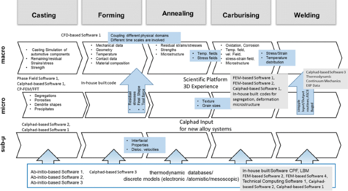
Requirement for information exchange
-
Through processing at the macroscopic scale typically requires the transfer of residual stresses and strains and temperature gradients. The cooling history during casting has an effect on the property development and the residual stress field, and this needs to be accounted for in the subsequent forming step. The residual stresses resulting from the forming step have an effect on the product shape in the subsequent annealing step. It is important to note that attention also has to be paid to the effect that specific phenomena have on different time scales, and hence, integration techniques have to account for this.
-
At the micro level, the exchange of grain sizes and texture are considered to be the most relevant properties.
-
-
4.
How do you do scale bridging?
Only limited multiscale analysis was performed by the attendants, and hence, the issue of scale bridging could not yet be sufficiently addressed. Microstructure simulations provided the insight and microstructure distribution. Appropriate input properties for the macroscopic properties are subsequently selected.
-
5.
What is your feeling about the maturity (TRL) level?
The response generated in the workshop on these two questions is summarized in Fig. 15.
Fig. 15 
Maturity level of analysis methods as seen by the workshop participants
It is obviously felt that the maturity level of macroscopic simulations is much higher than the micro- or sub-micro-level simulations. During the workshop, it turned out that simulation on the macroscale is widely accepted and used in industry on a technology readiness level (TRL, according to the European Commission definition) of 8–9. Microstructure evolution codes and even more detailed electronic, atomistic, and mesoscopic models by now have reached a TRL of approximately 4–5 or even less. Consequently, respective approaches are now only used in specialized laboratories. Nevertheless, the benefit for microscale/mescoscale/macroscale simulations is widely accepted and the need for downscaling is clearly formulated by the industrial attendants.
Care has to be taken, however, that even at the macroscale level, the maturity level of complete through process simulations is much lower than the simulation of a specific individual manufacturing step. This is partly due to the difficulty of data exchange between various analyses (spatial distribution using different meshes and data exchange between different software codes/analysis techniques)
Indeed, there are several serious hindering factors: the missing of general standards for data format and platforms (in particular, the user friendliness of small-scale models is limited in most cases), the limited simulation knowledge on the user side, expensive information technology capacities, and no license schemes for short-term, but challenging calculation projects have been mentioned.
A major gap has been identified between continuum mesoscale models and electronic/ab initio based models. The usability and the compatibility between these two model worlds have been formulated to be a major challenge for the future. Here, more success stories are needed to convince industry to increase activities on ICME.
-
6.
Do you have a suggestion for a sandbox scenario?
Three suggestions were generated during the workshop:
-
Macroscopic forming analysis followed by a heat treatment analysis for three different alloys
-
Translation of microscopic RVE simulations into macroscopic analysis
-
Additive manufacturing
These ideas will be further explored by the ICME expert group and will be discussed at the 2nd workshop to be held in Barcelona in April 2016.
-
-
7.
On which area do you have data suitable for experimental verification of the models?
Only limited information was obtained on this subject in this workshop. This topic will be further addressed at the 2nd workshop. The ICMEg working group has to identify examples for the sandbox scenario examples and will contact its industrial network to see whether sufficient experimental data are available.


Conclusion
ICME is seen as an evolving technology with academic and industrial interest. To become an integral part of the product design in terms of material (property) selection and product performance (manufacturing and product performance), some steps still need to be taken.
The availability of a standard for data exchange between the various tools will definitely speed up the acceptance of this technology. If only limited data exchange is possible (either due to lack of methodology such as scale bridging and remeshing techniques), only part of the potential is used.
The availability of a set of working demonstration problems or sandbox scenarios identifying how to do the integration, what information is needed, what is to be exchanged and how is this spatially distributed, and what time scale bridging is needed will speed up the acceptance of the integrated modeling.
Using numerical models, which are not robust and validated enough, in project running in an industrial environment will be seen as uncertain parts of the innovation project. Due to the critical time paths in a project, industry is removing these uncertainties by using alternative, more proven development routes rather than solving the imperfections in the models.
References
W. Voigt, Ann. Phys. 274, 573 (1889).
Frauenhofer IFMA, FOAMINAL_Properties Overview and Design Guideline, version 1.4, http://www.ifam.fraunhofer.de/content/dam/ifam/de/documents/IFAM-Bremen/2801/leichtbauwerkstoffe/metallschaeume/design/design_guidelines_english_V14.pdf. Accessed 18 Nov 2015.
J. Hol (Master thesis, University of Twente, 2009).
D. Helm, A. Butz, D. Raabe, and P. Gumbsch, JOM 63, 20 (2011).
M.G.D. Geers, V.G. Kouznetsova, and W.A.M. Brekelmans, J. Comput. Appl. Math. 234, 2175 (2010).
E.W.C. Coenen, V.G. Kouznetsova, and M.G.D. Geers, Int. J. Numer. Methods Eng. 83, 1180 (2010).
R. Tryon, and R. Matthews (Paper presented at the 52nd AIAA/ASME/ASCE/AHS/ASC Structures, Structural Dynamics and Materials Conference, Denver, CO, 4–7 April 2011).
www.vextec.com. Accessed 18 Nov 2015.
G.J. Schmitz, A. Engstrom, R. Bernhardt, U. Prahl, L. Adam, J. Seyfarth, M. Apel, C. Agelet de Saracibar, P. Korzhavyi, J. Agren, and B. Patzak, JOM. doi:10.1007/s11837-015-1718-8.
Author information
Authors and Affiliations
Corresponding author
Rights and permissions
About this article

Cite this article
Konter, A.W.A., Farivar, H., Post, J. et al. Industrial Needs for ICME. JOM 68, 59–69 (2016). https://doi.org/10.1007/s11837-015-1704-1
Received:
Accepted:
Published:
Issue Date:
DOI: https://doi.org/10.1007/s11837-015-1704-1