
Abstract
Leaf springs are widely used in the automobile industry due to its high load bearing capacity and low manufacturing cost. The usage of composite materials has gradually increased in the automobile industry due to its light weight and high strength to weight ratio. This work investigates the feasibility of using a low cost and light weight material for automobile leaf springs. We compare conventional steel EN45 leaf spring with several composite leaf springs such as carbon/glass epoxy, kevlar/epoxy and isotropic aluminum 6061 based on their load carrying capacity, deformation and stresses, strain energy storing capacity, natural frequencies, corrosion resistance, cost effectiveness, fatigue life and weight reduction. Static and dynamic analysis has been performed to study the benefits of using composite materials for leaf spring models, and our results show that kevlar/epoxy is the best among the selected materials for leaf spring as it induces lower stresses and has greater strain energy storage therefore leading to better ride quality. Carbon/glass epoxy and kevlar/epoxy have higher natural frequencies due to its lower mass and greater stiffness properties. The life cycle of kevlar/epoxy is greater to all materials due to its superior material properties. Use of kevlar/epoxy leads to 82.14% weight reduction in leaf spring when compared to EN45 steel; this in turn leads to decrease in the unsprung mass, therefore increasing ride quality, handling and mechanical efficiency of the vehicle.
Introduction
Leaf spring plays an important role in the vehicle suspension system. Due to its greater load bearing capacity and ability to absorb any vibration caused in the road, it is sought to be one of the greatest discoveries in the automobile market and provides customers with smooth and comforting rides. Leaf spring consists of a series of semi-elliptic leaves that are bonded together to contribute toward greater strength. Depending on its application, leaf springs are able to store a vast amount of strain energy on loading and release it slowly in order to prevent any rebound. The semi-elliptic leaf spring is mounted on the axle of the vehicle. The entire load of the vehicle has a static load on the spring (Table 1). The front eye end of the leaf spring is connected to the frame of the vehicle with the help of a simple pin joint. The rear eye end of the leaf spring is connected to a flexible shackle link allowing translational motion along x-axis. If both eye ends of the leaf spring are connected to fixed ends, during loading the leaf spring would not be able to adjust to the change in length of the leaves [1].
The introduction of composites in the automobile industry promoted greatly toward weight reduction in the automobile therefore increasing efficiency and performance. Composite materials consist of two or more materials that are physically assembled, therefore result being a mixture of all mechanical properties. This leads to a stronger and a more powerful component than just a single material [2]. Use of composite leaf spring shows greater strength and higher strain energy storing capacity when compared to steel leaf spring. Materials possessing lower values of elastic modulus and density have higher strain energy storing capacity. This is beneficial, as during loading the energy generated is stored between the leaves of the leaf spring and released slowly. This specific strain energy relationship of a material is given by:
where ‘σ’ is the Elastic Strength, ‘ρ’ is the Density, and ‘E’ is the Young’s modulus of the material [3].
A number of studies have been performed to replace conventional steel leaf spring with composite leaf spring to optimize the load carrying capacity, provide smooth ride quality and increase overall performance of the vehicle. The author has modeled the leaf spring taking design specification from Mahindra Commander Jeep 650 Di. The leaf spring model is tested for dynamic loading conditions, i.e., when the vehicle takes left or right turns (Table 2). The design specification of the leaf spring model is discussed in this paper. The author analyzed the results for different loading condition [4]. The authors of this paper performed static analysis on a mono leaf spring model. This model was taken from Maruti 800 passenger vehicle. The mono steel leaf spring is compared to three different composite leaf spring materials, i.e., E-glass/epoxy, S-glass/epoxy and carbon/epoxy. The leaf spring models are subjected to the same static load. The authors concluded that the use of laminated composite leaf spring shows better results when compared to mono steel leaf spring [5]. The objective of this research work was to compare the load bearing and weight reduction capacity of a composite leaf spring to that of conventional steel leaf spring. Static load analysis of the leaf spring model is performed in ANSYS Workbench, and the results are documented. The authors of this work concluded that composite leaf spring has 400% less weight when compared to conventional steel leaf spring [6]. The authors have described the design and analysis of a composite leaf spring model in this paper. They have compared the stresses and weight difference of composite leaf spring to that of steel leaf spring. The authors concluded in their research that use of E-glass/epoxy as a material for leaf spring shows lesser stresses to steel. Composites reduced the weight of the leaf spring by 81–92% when compared to steel [7]. The authors of this paper performed modal analysis of a leaf spring used by medium utility vehicle. The authors compared the natural frequency values obtained in ANSYS for both steel and composite materials with theoretical calculations. The results show that there was a slight difference the theoretical and numerical values of frequency obtained [8]. The authors of this paper carried out a research work on a multi leaf spring having five leaves used by a commercial vehicle. They replaced the existing steel material for multi leaf spring with composite material. Four different composite materials were analyzed such as E-glass/epoxy, graphite/epoxy, carbon/epoxy and kevlar/epoxy, and modal analysis was performed in ANSYS Workbench for each of the material property. Comparison was done between analytical obtained natural frequencies and theoretical values (Table 3). The results concluded that the obtained ANSYS results almost coincide with the theoretical modal analysis values. Harmonic analysis was also carried out to find out the resonance frequency of each material. This work concluded that use of composite materials led to weight reduction in the leaf spring model [9].
In the present study, a semi-elliptic leaf spring is subjected to static and dynamic loading condition using ANSYS Workbench. Four different materials are compared, i.e., EN45 steel, carbon/glass epoxy, aluminum 6061 and kevlar/epoxy. Through the results, kevlar/epoxy shows lower induced stresses and higher strain energy storing capacity due to which ride quality is benefitted. The fatigue life of kevlar/epoxy is higher to other materials due to its material properties and can undergo greater cycles of loading till failure. Kevlar/epoxy shows higher natural frequencies compared to EN45 steel and aluminum 6061 due to its mechanical properties. Use of kevlar/epoxy leads to superior weight reduction in the leaf spring which in turn increases the ride quality and mechanical efficiency of the vehicle (Table 4).
Methodology

Design Specifications
Leaf Spring Design Specifications
The leaf spring specifications are taken from the model ‘Mahindra Commander Jeep 650 Di’ and are specified below [10].
There are four semi-elliptic leaf springs used in this analysis, i.e., conventional steel EN45, carbon/glass epoxy, isotropic aluminum 6061 and kevlar/epoxy. The mechanical properties of each material are listed in the ‘Appendix’ section in Appendix Tables 6, 7, 8 and 9.
Specification of Mahindra Commander Jeep 650 Di
-
Weight of Vehicle = 1450 kg [11]
-
Additional weight allowed = 550 kg
-
Total weight = 2000 kg
-
Safety factor = 1.33 [12]
where ‘m’ is mass of the vehicle, ‘g’ is acceleration due to gravity, and ‘FOS’ is the factor of safety.
Since the vehicle is a four-wheeler, a single semi-elliptic leaf spring takes up to 4th of the total weight [13].
Modeling
The 3D modeling of the semi-elliptic leaf spring is carried out in Solid works 2016 for the above specified design parameters. Each of the parts has been modeled separately and then assembled together using assembly mates. Mates assign geometrical relationship between various components of the assembly. When mates are assigned, it defines the allowable direction of motion (translational or rotational) of each component of the assembly. The leaf spring assembly is then imported to ANSYS Workbench for static and dynamic analysis (Fig. 1).

Assembly model of semi-elliptic leaf spring
Meshing and Boundary Condition
Mesh represents the geometry in the form of nodes and elements in the design modeler. For this geometry, relevance is set to 100 leading to finer mesh. Advanced size function is turned on with the maximum face size assigned 6 mm. The fixed advanced function does not refine the leaf spring model on the basis of proximity and curvature but refines the entire model as a single entity. A refinement command with a depth of 2 is assigned therefore leading to splitting of the edges of elements into half elements. In the solution information under the adaptive mesh refinement segment, the maximum refinement loop is taken as 3, while a refinement depth of 2 is assigned [14]. Figure 2 shows the meshed model of the semi-elliptic leaf spring. The front eye end Fig. 3a of the leaf spring is constrained in all directions as it is connected to a fixed end. The rear eye end Fig. 3b is connected to a shackle link therefore allowing translational motion along x-axis, while all other DOFs are constrained. This is done to simulate loading similar to real-life conditions. Load is applied uniformly on the bottom most leaf toward positive y-axis Fig. 4.

Meshed model of leaf spring assembly

(a) Front eye end constraints and (b) rear eye end constraints

Loading condition (force applied uniformly to the bottom surface of the 10th leaf in positive y-direction)
Theoretical Validation
The first step is to find out whether the leaf spring is operating under safe conditions; this is given by,
where ‘F’ is the force applied to leaf spring, ‘L’ is length of the leaf spring, ‘n’ is the number of leaves, ‘b’ the width, and ‘t’ thickness of leaf spring (Fig. 5).

Von Mises stress in each material and maximum allowable stress
The above equation provides a comparison between theoretical calculations and obtained ANSYS Results. Loading is done from 6523.65 to 15,000 N, and the results are as follows:
-
The stresses induced in EN45 steel, carbon/glass epoxy, aluminum 6061 and kevlar/epoxy are lower than the maximum allowable stress limit; from this, the conclusion devises that the leaf spring is operating under safe conditions.
Results
Static Structural Analysis
The vehicle is assumed to be stationary, and the leaf spring undergoes static loading condition and analyze the von Mises stress, total deformation and strain energy values for each material property [10]. The load acting on the leaf spring equals 6523.65 N which is shown in Fig. 3. Results obtained for deformation, von Mises stress and strain energy are shown below in Figs. 6, 7, and 8.

Deformation (mm) in each material

Von Mises stress (MPa) in each material

Strain energy (mJ) in each material
Modal Analysis
Modal analysis is used to determine the natural frequency and mode shapes of a structure under free vibrations. The natural frequency and mode shapes are the most important design parameters for a model undergoing dynamic loading. The obtained natural frequencies for each material property should be higher than the frequency of road irregularities, i.e., 12 Hz [15, 16]. In ANSYS Workbench, the Lanczos algorithm is used for formulating the eigenvalues (natural frequencies) and eigenvectors (mode shapes) (Fig. 9).

Natural frequency (Hz) for each material up to 6 modes
After modal analysis is performed and the mode shapes and natural frequencies are obtained for each material, harmonic response module in ANSYS Workbench is linked to the solution cell of modal analysis domain; this is done to obtain the maximum response and corresponding frequencies.
A load of 6523.65 N is applied harmonically and frequency is varied from (0 to ∞), and the response is then plotted. The resonating points obtained must be carefully dealt with while designing the structure. The theory behind harmonic response analysis is mode superposition theorem; the dynamic response of a structure can be formulated by superposition technique of small number of eigenvalues. This in turn reduces the overall computation time. A pre-requirement for mode superposition is to obtain the natural frequencies and mode shapes [17]. ANSYS uses Rayleigh’s damping to find out the response at each frequency. If no damping is incorporated the response would shoot to ‘∞.’
Rayleigh’s damping given by,
where [C], [M], [K] are the damping, mass and stiffness matrix, α, β are constants of proportionality [18].
The frequency response of deformation and equivalent von Mises stress is obtained for each material property. Figures 10, 11, 12 and 13 represents the frequency response of deformation for each material.

Frequency response of deformation EN45 steel

Frequency response of deformation carbon/glass epoxy

Frequency response of deformation isotropic aluminum 6061

Frequency response of deformation kevlar/epoxy
The frequency sweep for each material is taken in the range lower than the first natural frequency up to the fourth natural frequency. This is done to reduce the overall memory allocation and processing time required by the system.
Using the same frequency range for each material property, the maximum von Mises stress is plotted in Figs. 14, 15, 16 and 17.

Frequency response of maximum von Mises stress EN45 steel

Frequency response of maximum von Mises stress carbon/glass epoxy

Frequency response of maximum von Mises stress aluminum 6061

Frequency response of maximum von Mises stress kevlar/epoxy
Fatigue Life Analysis
Fatigue life is the number of cycles that a structure sustains before failure. It is the weakening of a structure due to repeated applied stresses also known as cyclic loads. It is the progressive damage caused due to these repeated cycles of load. If the applied cycles of load are above a certain limit, microscopic cracks occur in the structure which develops over time leading to permanent structure fracture (Figs. 18 and 19).

Fatigue life in each material

Fatigue sensitivity EN45 steel
Using Hwang and Han Relation:
where B = 10.33, c = 0.14012.
where ‘N’ number of cycles to failure, ‘r’ applied stress level, ‘σmax’ maximum stress, ‘σUTS’ ultimate tensile strength.
From this, the alternating stress mean stress diagram for each material is plotted and then imported to ANSYS Workbench Engineering data. The alternating stress mean stress diagram is available in the ‘Appendix’ section (Figs. 20 and 21).

Fatigue sensitivity carbon/glass epoxy

Fatigue sensitivity aluminum 6061
A fully reversed constant amplitude load of 6523.65 N is applied, when R (Stress ratio) = − 1 and A (Amplitude ratio) = ∞
where ‘σalt’ alternating stress (MPa), ‘σmean’ mean stress (MPa), and ‘σmax’ minimum stress.
Fatigue Sensitivity
Fatigue sensitivity represents the variation of fatigue results as a function of loading at critical locations in the leaf spring [15]; this plot below shows the sensitivity plot for life for each material property when subjected to cyclic loading (Fig. 22).

Fatigue sensitivity kevlar/epoxy
Comparison in Weight
Weight reduction is crucial as it leads to greater mechanical efficiency and better ride quality of the automobile. As leaf spring accounts for the unsprung mass of the vehicle, reduction in the unsprung mass leads to lesser vertical acceleration forces, while vehicle is in motion; this in turn increases ride quality and handling.
Table 5 shows the percentage weight comparison in semi-elliptic leaf spring [1]. This is performed by comparing EN45 steel leaf spring to carbon/glass epoxy, kevlar/epoxy and isotropic aluminum 6061 leaf springs.
Conclusions
In this research work, a comparative study has been made between several composite leaf springs to conventional steel EN45 leaf spring. The composites used in the research are carbon/glass epoxy, kevlar/epoxy and isotropic aluminum 6061. This study is done to compare the deformation, von Mises stresses, strain energy, natural frequencies, frequency response, fatigue life and %weight reduction obtained for each material property.
The conclusions are as follows:
-
1.
During static analysis, deformation is seen higher in kevlar/epoxy when compared to EN45 steel; this is due to lower modulus of elasticity in composite materials. As the deformation is high, this leads to discomfort in vehicle ride. It is observed that when load is applied to each composite leaf spring the stresses induced are lesser compared to EN45 steel leaf spring. This shows that composite leaf springs can bear higher amounts of load and induce lower stresses when compared to EN45 steel.
-
2.
It is observed that composite leaf spring stores a huge amount of strain energy during loading and release it slowly; this is due to composites having lower values of density and Young’s modulus. This in turn leads to improved vehicle suspension system leading to better ride quality and ride handling. Kevlar/epoxy and aluminum 6061 have higher strain energy storing capacity and induce lower stresses in the leaf spring. This is mainly due to its better mechanical properties.
-
3.
Through modal analysis, it is observed that carbon/glass epoxy and kevlar/epoxy show higher first natural frequencies due to its greater stiffness and low mass properties. This is better as greater excitation frequency is required to cause structural damage to the carbon/glass epoxy and kevlar/epoxy Leaf spring.
-
4.
Frequency response of deformation shows the deformation caused when the leaf spring is excited to its natural frequency; this comparison is done for each material property. Each of the materials undergoes structural damage. EN45 steel leaf spring shows the lowest deformation as it is excited at a frequency lower than that of carbon/glass epoxy and kevlar/epoxy leaf springs. Therefore, if the leaf spring is excited to its natural frequency, it will undergo structural damage and also affect vehicle ride quality
-
5.
Using harmonic response, the maximum von Mises stress was estimated, and it is seen that EN45 steel and aluminum 6061 leaf spring induce lower stresses when excited to its natural frequency when compared to the carbon/glass epoxy and kevlar/epoxy.
-
6.
Kevlar/epoxy and EN45 steel leaf springs possess superior mechanical properties, therefore showing higher fatigue life compared to carbon/glass epoxy and aluminum 6061 leaf springs. Therefore, kevlar/epoxy and EN45 steel can undergo greater cycles of loading till failure.
-
7.
Through fatigue sensitivity for life, kevlar/epoxy leaf spring showed better results as the maximum and minimum life at the critical locations of the leaf spring is greater when compared to EN45 steel, carbon/glass epoxy and aluminum 6061 leaf springs. Kevlar/epoxy leaf spring is an optimum performer under cyclic loading.
-
8.
Automakers have said that lower the unsprung mass of the vehicle, lower the vertical accelerations forces caused when the vehicle is in motion. In Fig. 23, the weight of kevlar/epoxy leaf spring is lesser by 82.14% compared to steel EN45 leaf spring, carbon/glass epoxy leaf spring is lesser by 78.7% compared to steel EN45 leaf spring. Using aluminum 6061 leaf spring shows 51.8% lesser weight when compared to steel EN45 leaf spring. This benefits the automobile as the mechanical efficiency and performance is improved. Fuel consumption is lesser therefore overall fuel economy increases.
Fig. 23 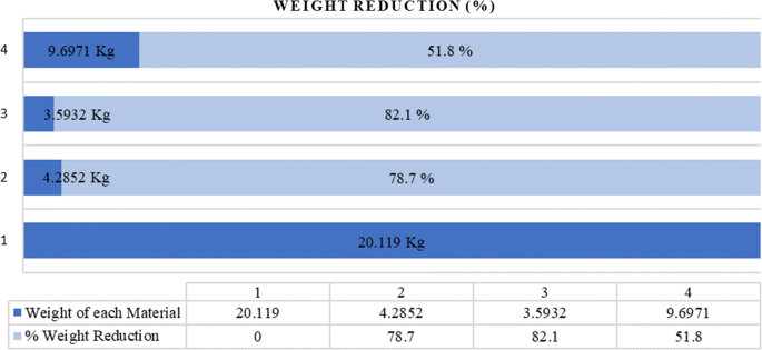
Percentage weight reduction in composite materials with EN45 steel

Through this study, a conclusion is made that kevlar/epoxy is the most optimistic material for automotive leaf spring. The deformation is high in the case of kevlar/epoxy leaf spring, which causes slight discomforts in the ride quality. Due to the weight reduction achieved in kevlar/epoxy Leaf spring, the overall vehicle efficiency and performance has been improved.
References
M.K. Salman, A.P. Singh, S. Roy, J. Banerjee, Numerical investigation of parabolic leaf spring for composite materials using Ansys. Int. J. Eng. Res. Appl. 8(1), 58–69 (2018)
F.C. Campbell, Introduction to Composite Materials (ASM International, Cleveland, 2010)
M.K. Gaffar Abbas, A. Niakan, C.M. Chia, R. Singh, P. Teo, Design and numerical analysis of leaf spring using composite materials. Key Eng. Mater. 723, 305–310 (2017)
R. Mistry, Dynamic analysis of a leaf spring. IJREAT 2(2), 638–640 (2014)
M. Raghavedra, S.A. Hussain, V. Pandurangadu, K. PalaniKumar, Modeling and analysis of laminated composite leaf spring under the static load condition by using FEA. IJMER 2(4), 1875–1879 (2012)
V. Trivedi Achyut, R.M. Bhoraniya, Static and dynamic analysis of automobile leaf spring (TATA ACE). IJSTE 1(11), 151–156 (2015)
P. Saini, A. Goel, D. Kumar, Design and analysis of composite leaf spring for light vehicles. IJIRSET 2(5), 1–10 (2013)
Y.Y. Kamble, S.H. Sawant, Modal analysis of composite leaf spring used for medium utility vehicle. Int. J. Adv. Res. Sci. Eng. 4(1), 764–771 (2015)
P.S. Rao, R. Venkatesh, Modal and harmonic analysis of leaf spring using composite materials. Int. J. Novel Res. Electr. Mech. Eng. 2(3), 67–75 (2015)
M.P. Jenarthanan, S. Ramesh Kumar, G. Venkatesh, S. Nishanthan, Analysis of leaf spring using carbon/glass epoxy and EN45 using ANSYS: a comparison. Mater. Today Proc. 5(6), 14512–14519 (2018)
S. Nutalapati, Design and analysis of leaf spring by using composite material for light vehicles. IJMET 6(12), 36–59 (2015)
S. Harshit, A. Verma, Design and simulation of leaf spring for TATA-ACE mini loader truck using FEM. IJIR 2(10), 1362–2454 (2016)
R. Ghosh, S. Ghosh, S. Ghimire, R.N. Barman, Static analysis of multi-leaf spring using Ansys workbench 16.0. Int. J. Mech. Eng. Technol. 7(5), 241–249 (2016)
A. Bhanage, K. Padmanabhan, Design for fatigue and simulation of glass fibre/epoxy composite automobile leaf spring. ARPN J. Eng. Appl. Sci. 9(3), 196–203 (2014)
M. Senthil Kumar, S. Vijayarangan, Static analysis and fatigue life prediction of steel and composite leaf spring for light passenger vehicles. J. Sci. Ind. Res. 66, 128–134 (2007)
Comsol.com, Mode superposition definition (2019)
Geotechsimulation.com, Application of Rayleigh damping and numerical damping in finite element/difference analysis—GeoTechSimulation (2019)
Author information
Authors and Affiliations
Corresponding authors
Additional information
Publisher's Note
Springer Nature remains neutral with regard to jurisdictional claims in published maps and institutional affiliations.
Rights and permissions
About this article

Cite this article
Noronha, B., Yesudasan, S. & Chacko, S. Static and Dynamic Analysis of Automotive Leaf Spring: A Comparative Study of Various Materials Using ANSYS. J Fail. Anal. and Preven. 20, 804–818 (2020). https://doi.org/10.1007/s11668-020-00877-y
Received:
Published:
Issue Date:
DOI: https://doi.org/10.1007/s11668-020-00877-y