
Abstract
The trajectory of the actual gas drainage drilling often deviates from the design in the process of gas control drilling construction, resulting in the deviation of the drilling. The deviation may produce blind areas of gas drainage and induces potential safety hazards. In the present study, we use theoretical analyses and numerical simulations to study the deviation principles of gas drainage borehole in three-soft outburst coal seam. The following conclusions are drawn from our new data: Considering mechanical bending, geometric bending, and other factors that affect the drilling deviation, the deviation mechanism during the drilling process of the drilling rig has been analyzed and we have obtained a mechanical model of the gas drainage drilling rig under the conditions of vertical upward, horizontal and different inclination angles. We have detected the drilling pressure and the weight of the drill pipe as the main influencing parameters of the drilling deviation, providing a theoretical basis for the main influencing parameters of the deviation in the drilling process. In FLAC3d numerical simulation experiment, the displacement around the borehole is limited and the borehole area remains relatively stable and basically unchanged. The overall stress distribution shows a layered structure that largely corresponds to the distribution of the rock sequence. The areas of stress concentration are mainly located in an area of a rock sequence (interlayered mudstone and limestone)) with differing properties, the coal seam area, and the drilling hole location, and the drilling hole is prone to deflection in these areas. The drilling trajectory is mainly influenced by geological factors, equipment factors, and human factors. We propose the combination of a drilling control method and an inclination control method for controlling the influence of machine equipment and human factors in the actual field application. The inclination angle of the borehole deviation is controlled within a certain range to achieve a reduction of the borehole deviation of gas as a suitable reference value in the engineering application.
1 Introduction
In 2019, Chinese coal production accounted for about 47.4% of the global coal production, indicating the important strategic position of coal for the economic development of China. Gas is the main cause of various accidents during the mining process. Insufficient control of the gas may cause coal and gas outburst accidents, causing serious damage to underground facilities, endangering the lives of underground staff, and thus affecting the safe and efficient mining of the coal mines (Xiong et al. 2021a, b).
Gas pre-drainage technology is one of the main effective means to prevent coal and gas outburst. The consistency of the gas drainage borehole and the design borehole is the precondition to ensure safe and efficient gas drainage. However, borehole deviation is ubiquitous in actual engineering applications, resulting in an uneven distribution of the coal seam boreholes, dense boreholes in some areas, and string hole phenomenon may occur during drilling. Some areas are blind areas of drilling, and the gas stock is still high after extraction, which may cause safety hazards in the mining process (Shen et al. 2020). Three-soft coal seam is a coal seam with soft roof, soft floor, and soft coal. Joints and fissures are developed in these coal strata, the strength is low, and its shape is easily affected by external forces (Yang and Zhang 2020; Kong et al. 2021). In areas of three-soft coal seam drilling, drilling deviation is specifically prominent. Therefore, studying and understanding the principles of the borehole deviation and controlling the extent of the deviation can effectively reduce the described deficiencies, so that the actual drilling trajectory and the design drilling trajectory are combined to improve the efficiency of gas extraction.
To achieve an efficient gas drainage, it is necessary to clarify the stress distribution, the permeability distribution around the borehole, and the effective influence radius of gas drainage. Several studies have focused on these objectives. Some scientists have used the Kozeny-Carman equation to establish the gas–solid coupling mathematical model of coal and rock, obtained the stress distribution principles on both sides of the borehole by simulation analysis, clarified the effective influence radius of the borehole, and documented the applicability of the gas extraction and multi-physics coupling model in coal mines (Tang et al. 2019). After detecting the distribution characteristics of coal seam permeability, the set-up of the gas drainage boreholes in protected coal seam during protective layer mining has been optimized by numerical simulations and field applications. Practice and experience have shown a significant increase of the amount and concentration of gas drainage after optimizing drilling arrangement (Cheng et al. 2020). Subsequently, the three-dimensional deformation characteristics of the borehole have been studied experimentally by borehole stability dynamic monitoring device to achieve the dynamic monitoring of the borehole stability in gas drainage (Zhao et al. 2020). To refine the evolution of the rock permeability, based on the characteristics of permeability zoning, the layout parameters of drainage boreholes have been quantitatively analyzed by numerical simulations, which effectively reduced the workload of the drainage boreholes in the protective layer and protective layer working face (Fan et al. 2021a, b). Moreover, with progress of the drilling equipment, directional drilling has the advantages of a controllable trajectory and wide coverage area. Therefore, its use range has been gradually increased. Numerical simulation analysis can provide a suitable solution to the problematic gas concentration overrun in upper corner of goaf and return airway (Shang et al. 2021). Measurement while drilling is a rock mass characterization method that can be used to obtain drilling parameters. By subjecting the data to multiple linear regression, a holistic visualization method is derived that relates the drilling parameters to rock mass classification and rock support requirements (Jeroen et al. 2020). Using the energy balance method and the drilling process monitoring system to conduct orthogonal tests on granite, the sensitivity of each drilling parameter to drilling efficiency is obtained. Base on the gained data a reasonable selection of drilling parameters can be realized (Li et al. 2020). Horizontal directional drilling technology can significantly improve gas drainage efficiency. Based on the mechanical properties of coal, a linear elastic drilling model has been constrained to analyze the drilling stability and to realize the prediction of drilling stability (Hawkes, 2007). Based on drilling stability analysis, combined with the hole wall mud pressure model, the linear elastic drilling model provides a basis for extending the scope of technical application (Yan et al. 2018). Based on the coal seam gas occurrence and flow theory, and the gas radial flow differential equation, the coal seam gas flow equation is obtained by inversion, the borehole stress is analyzed, and the stress distribution diagram is acquired impact (Song and Xie 2011). To clarify the relationship between the number of boreholes and the extraction time, the evolution of the influence radius around the borehole in the anisotropic coal seam has been simulated, the elliptical influence range of the borehole in the anisotropic coal seam has been proposed, and the influence radius of the borehole and the extraction time has been obtained relationship. Application of this method can effectively reduce the drilling costs and will increase the coal mining output (Yue et al. 2019). To analyze the principles of the stress redistribution under the influence of circular roadway, numerical simulations on the stability of gas drainage boreholes in the stress redistribution area have been conducted. The model of the vertical intersection of the circular roadway and the gas drainage borehole has been established, and the internal friction angle and the cohesion have been identified as the factors that affect the stress distribution around the borehole (Zhang et al. 2015). For soft coal along the bed, the traditional drilling technology has been optimized based on the movement process of the coal body during the drilling process, and the parameters, such as drilling tool power and torque, have been adjusted. The method can effectively improve in the engineering application the drilling efficiency in the soft outburst coal seam, ensuring the full coverage of gas drainage in the working face (Cao 2021). Horizontal long drilling on the roof is an important method of gas drainage. Through the Discrete Element Method (DEM) and the establishment of a mathematical model the accurate positioning of the gas conduction fracture zone has been achieved, thereby effectively reducing the gas concentration in the goaf (Fan et al. 2021a, b). To determine the stress in the coal body along the hole depth during the coal seam drilling process, a three-dimensional numerical simulation model of dynamic coal breaking by the drill bit has been established, and the coal body drilling process under different coal body stress conditions has been studied. The fitting relationship between the drilling parameters and the stress in the coal body has been obtained, providing a data basis for drilling in high-stress coal seams (Zheng et al. 2021). For the selection of the drainage radius, numerical simulation software has been used for the analysis. Based on the modelling a close correspondence between the drainage influence radius and the drainage period has been obtained. The findings provided the base for good results in the engineering applications (Xu et al. 2016). Fu et al. (2017) divided the deflection trajectories into four categories according to the position of the drilling offset holes. They analyzed the extraction effects and characteristics of the various types of drilling holes to provide a basis for the optimal set-up of high-level drilling. Aiming at the problem of drilling deflection in gas drainage along the coal seam, theoretical analysis, numerical simulation, and field test can be conducted to study and analyze the deflection factors and conditions of the drilling along the coal seam (Liu 2020). At the same time, an analytic hierarchy process (AHP) model can also be established based on geological factors, technical factors, and human effects. The impact of each influencing factor is analyzed in the model, and it has been concluded that the main controlling factor that affects borehole deflection is soft and hard inter-layers (Sun et al. 2021).
Parameters, such as gas borehole stress distribution, permeability distribution, and drainage radius, have been investigated in several previous studies and based on the data, some effective methods and measures for controlling borehole deflection have been proposed. However, the deflection principles were poorly defined by the previous studies, inhibiting a qualitative and quantitative analysis of the deflection principles. In the actual construction process, it can still only rely on experience and cannot be applied on a large scale. Specifically in the three-soft coal seam, coal seam, roof, and floor cracks are developed, the coal and rock mass structure are soft, and the compressive strength is low. During the drilling process, the shape of the coal seam is very easily disturbed by external forces, resulting in the deflection of the drilling hole and thus preventing the precise drilling into the target area to achieve efficient gas drainage. Therefore, we have obtained the principles of the deflection angle of the gas drainage boreholes in line with the actual three-soft coal seams through theoretical analysis and numerical simulations, and considering the characteristics of the three-soft strata. Then, through the quantitative calculation of the deflection angle of the function, the main factors affecting the drilling trajectory are obtained. The angle can be corrected in advance and in time prior to the construction and during the drilling process to improve its effect of the actual application, and to avoid serious deflection of the designed gas drainage boreholes, and the occurrence of blind areas of gas drainage. Our study will provide a basis for borehole drilling in mines with a comparable problematic geological situation.
2 Mechanism Analysis of Borehole Deviation
2.1 Mechanism Analysis
The main factors causing the deviation of gas drainage boreholes in the construction process of on-site gas drainage boreholes can be subdivided into three aspects: The influence of geological factors, construction technical factors, and human activities on the working face of the gas drainage drilling site. The change of the geological conditions is a continuous weak modification, mainly reflected in the strata and the thickness of the change. Technical factors, even if mature technologies are applied to field practice, will cause certain deviations, and some technologies may induce inevitable technical deviations. These influencing factors accumulate and affect the trajectory of gas drainage boreholes, resulting in the deviation of the gas drainage boreholes. Finally, human factors cause rather subjective changes. The experience and ability of member of the construction team of site construction is uneven and the understanding of the equipment may be improper. These uncertainties may easily cause the trajectory deviation of gas drainage borehole, which reduces the efficiency of the gas drainage borehole.
Although the causes of borehole deviation can be summarized from the influencing factors, the drill pipe runs through the entire construction process, which is necessary for the theoretical analysis of the bending of the drill pipe. Therefore, mainly the mechanics, geometry, and other factors affect the analysis of the bending.
2.1.1 Mechanical Factor
The bending deformation of the force of the drilling tool system occurs during the construction of the gas drainage drilling rig. The resultant force in the vertical direction of the drill pipe of the gas drainage drilling rig in the drilling process can be decomposed into three main forces, i.e., the gravity of the drill pipe weight, the axial force acting on the drill pipe by the propulsion pressure of the gas drainage drilling rig, and the force acting on the drill bit by the reverse force. The drill pipe will shift in the direction of the resultant force if the three forces are not balanced. Since the surface of the broken rock is uneven, bumpy, or tooth-like and the rock hardness of the broken rock surface is variable, the blade of the drill bit has a certain angle, which causes an unstable vertical reaction force on the drill bit and the reverse force will change. The drill pipe in the gas drainage borehole can be regarded as a slender and elastic rod. In case of an unstable force, it will produce a small vertical deviation, resulting in the shift of the position of the central axis of the drill pipe and the axial pressure acting line provided by the drill rig, resulting in the deviation of the vertical direction of the drill pipe (Yu 2020). The lateral force of the drill pipe is the contact force between the drill bit and the rock at the bottom of the hole diameter and the friction force between the drill pipe and the rock at the hole wall. Like the vertical force, the unbalanced lateral force will cause the lateral deviation of the drill pipe, resulting in the lateral force of the drill pipe and the slight displacement of the drill pipe in the lateral direction. Torsion force in the drilling process of anchor drill is the torque of thrust pressure acting on drill pipe and rock reverse acting on drill bit. If the torsional force of the drill pipe is unbalanced, when the rock cut by the drill bit is an irregular rock, the reverse torque of the drill bit is different from the torque transmitted to the drill pipe by the main engine. As the two equal reverse torques are different, the drill pipe will be subject to changing torque force, so that the drill pipe is rotated in the process of rotation, affecting the speed of the drill pipe. However, due to the torsional resistance of the drill pipe, the torsional force has only a minor effect on the deviation of the drill pipe.
2.1.2 Geometry
In the drilling process of gas drainage drilling rig construction, the geometric deviation is mainly caused by the measurement error of opening angle and the performance of drilling rig equipment. In the drilling process of drilling rig, there are mainly on-site construction personnel to determine the opening angle by adjusting the inclination angle of the equipment. However, in the measurement process, due to human subjective factors will cause the deviation of the opening angle, and the accuracy of the instrument has certain limitations, will cause the deviation of the opening angle of the gas drainage drilling rig, resulting in the deviation of the gas drainage drilling hole.
2.1.3 Other Factors
During the drilling process of the gas drainage drilling rig, the generated cuttings cannot be discharged from the drilling in time. When the cuttings continue to accumulate and block the gap between the drill pipe and the drilling, the rotary resistance of the drill pipe will increase, the drilling speed will be reduced, and the drill pipe will deviate due to the radial force.
2.2 Construction of Mechanical Model
2.2.1 Horizontal Drilling Conditions
The drill pipe force model of gas drainage drilling rig during horizontal drilling is shown in Fig. 1. FT is the thrust of the drilling machine. M is the rotation torque. α is the dip angle of the rock surface. FS is the resistance of rock to the edge tooth of the bit. FZ is the rotational resistance. N is the support force. M1 is rock face rotary resistance moment of bit side teeth. M2 is drilling tool system bending moment. The radius of the drill pipe is R and the length of the drill pipe is LZ (Yang, 2017; Liu et al 2021).

Horizontal drilling condition
Figure 1 shows that the drill pipe in the yoz plane is forced on the Z axis \(F_{{{\text{z1}}}} = F{\text{scos}}\alpha { - }N{\text{sin}}\alpha\). The bending moment of the drill pipe is M2. According to the formula of deflection and bending moment corresponding to material mechanics, the displacement and rotation angle of the drill pipe on the yoz surface are:
FS: the resistance of rock to the edge tooth of the bit, (N), α: the dip angle of the rock surface, N: the support force, (N), LZ: the length of the drill pipe, (m), M2: drilling tool system bending moment, (N M), EI: anti-bending coefficient
R; the radius of the drill pipe, (m), FT: the thrust of the drilling machine, (N), F: the resultant force in the x direction (N), f: coefficient of friction, By substituting (Eq. 3), (Eq. 4) and (5) into (Eq. 1) and (Eq. 2) respectively, we obtain the equations:
Axial pressure is defined as:
Fd: axial pressure provided by drilling rig.
We obtain the equations:
The rotating resistance of the drill pipe is defined as:
Fz: the rotating resistance of drill pipe, M1: rock face rotary resistance moment of bit side teeth, (N M).
The rotary resistance of the drill bit caused by rock properties can be ignored, and the relationship between axial pressure Fd of drill rig and rotary resistance moment M1 is expressed as:
k: proportional coefficient between axial pressure provided by drilling rig and rotary resistance; i: index, i > 0.
According to the formula of material mechanical deflection and rotation angle, it becomes evident that the displacement and rotation angle of the bit on xoy surface caused by Fz are obtained from the equations:
2.2.2 Vertical upward drilling condition
The force model of the vertical upward drill pipe and the force diagram are shown in Fig. 2. FT is the propulsive force, nW2 the weight of drill pipe, W1 the weight of moving parts, M is rotation torque, and the direction of the torque is consistent with the rotation direction of the drill bit. N is the support force, FS the sliding resistance, FZ the rotational resistance, and the direction is opposite to the direction of rotational torque M.

Vertical upward drilling condition
Figure 2 illustrates that the drill pipe is on the yoz surface, and the force is \(F_{{\text{y}}} = F_{{\text{s}}} {\text{cos}}\alpha + N{\text{sin}}\alpha\) along the y axis. The bending moment on the yoz plane is M2.
According to the corresponding deflection and bending moment of material mechanics, the displacement and rotation angle of drill pipe on yoz plane is:
FS: the sliding resistance, N: the support force, M2: the drilling tool system bending moment, (N M), FT: propulsive force, nW2: the weight of the drill pipe, W1: the weight of moving parts, M: the rotation torque, FZ: rotational resistance, M: the direction is opposite to the direction of rotational torque.
By substituting (Eqs. 17–18), and (Eq. 19) into (Eq. 15) and (Eq. 16), respectively, we obtain:
Due to axial pressure, we can define:
and we get the following equations:
The rotating resistance of the drill pipe is defined as:
According to the formula of deflection and rotation angle of material mechanics, and (Eq. 25) and (Eq. 12), we conclude that the displacement and rotation angle of drill bit caused by FZ on xoy surface are:
2.2.3 Drilling conditions at any angle
The schematic diagram and stress diagram of the drill pipe under arbitrary angle drilling condition are shown in Fig. 3. FT is the propulsive force, nW2 the weight of the drill pipe, W1 the weight of moving parts, M the rotation torque, and the direction of the torque is consistent with the rotation direction of the drill bit. N is the support force, FS the sliding resistance, FZ rotational resistance, and the direction is opposite to the direction of rotational torque M.

Drilling conditions at any angle
β is the angle between the drill pipe and the shaft in Fig. 3, hence, the angle of the inclination drilling the body. On the y’oz’ plane, the stress of the drill pipe along Z’ direction is FS at LZ and \(- (W_{1} + {\text{n}}W_{2} ){\text{cos}}\beta\) at \(\frac{{L_{Z} }}{2}\). The bending moment of the drilling tool system is M2.
According to the corresponding deflection and bending moment of material mechanics, the displacement and rotation angle of the drill pipe in the drill pipe drilling face is calculated from the equations:
β: the angle between the drill pipe and the shaft, FT: propulsive force, nW2: the weight of the drill pipe, W1: the weight of moving parts, M: the rotation torque, N: the support force, FS: the sliding resistance, FZ: rotational resistance, M: the direction is opposite to the direction of rotational torque.
The stress along the drill pipe direction is defined as:
By substituting (Eq. 30), (Eq. 31), and (Eq. 32) into (Eq. 28) and (Eq. 29), respectively, we obtain:
Due to axial pressure, it follows:
and get the following equations:
The displacement and rotation angle of drill bit on x’oy’ plane caused by FZ' are:
2.2.4 Conclusion Analysis of Mechanical Model
Based on the above mathematical relationships of drill pipe drilling deviation under different drilling conditions, it is evident from the offset equations (Eq. 9), (Eq. 13), (Eq. 23), (Eq. 26), and (Eq. 38) that the magnitude of offset is proportional to the coaxial force Fd during drilling. The equations for the migration angle (Eq. 10), (Eq. 16), (Eq. 21), (Eq. 27), and (Eq. 39) document that the magnitude of the migration angle during drilling is also proportional to the coaxial pressure Fd. In addition, the equations for the offset and the offset angle along y’ and surface y’oz’ (Eq. 36) and (Eq. 37) under any angle drilling conditions indicate that the main term of the deviation relationship is proportional to the axial thrust Fd, and the additional term of the two equations is the deviation caused by the weight of the drill pipe. According these findings, the deviation of the drilling can be reduced by controlling the process of the drilling rig.
3 Numerical Simulation of Drilling Trajectory
3.1 Numerical Modeling
Implementing the geological data provided by the mine and the lithologic histogram of the area, we established a numerical model. The model is mainly affected by the self-weight stress. The displacement boundary conditions are as follows: At the bottom of the model, the Z axis direction constraint is applied on the Z = 0 plane, the Y axis direction constraint on the front and rear sides of the model, and the X axis direction constraint on the left and right sides of the model. Stress boundary conditions: The model is mainly affected by the self-weight stress of the buried depth of 330 m. Therefore, a vertical downward load of 13 MPa is applied in the modeling. The model dimension is 200 m*100 m*50 m, and the constitutive model is a Mohr–Coulomb elastic–plastic material model. According to the engineering ground stress data, the roadway excavation is conducted after the ground stress reaches equilibrium (Xiong et al. 2021a, b). The numerical simulation model is shown in Fig. 4.

Numerical Simulation Model
The rock mass is a complex and diffuse system and represents a heterogeneous anisotropic body. As major fracture system occurs in the rock mass, it is very difficult to accurately determine the mechanical properties of the rocks. The parameters used in the modeling are summarized in Table 1.
3.2 Analysis Of The Simulation Results
According to the x–x stress distribution (Fig. 5), the maximum stress is 2.3 MPa and the minimum stress is 1.28 MPa (Fig. 5a). The stress distribution generally shows a left and right symmetrical state, and the stress distribution exhibits a marked layered structure. The stress value of limestone–mudstone associations and coal seams is larger. In the early stage of drilling, a marked stress concentration area appears at the hole opening position, which is mainly concentrated around the borehole (Yao 2016). In Fig. 5b, the maximum stress is 2.36 MPa and the minimum stress is 1.73 MPa. The stress distribution is generally concentrated around the borehole, and the stress distribution shows a marked layered structure. However, in the soft and hard interbeds of limestone and mudstone, the stress between the two boreholes and the surrounding area is obviously large, and it is mainly concentrated to the area around the borehole. An obvious stress concentration area occurs in the opening position of the borehole, and the stress concentration degree increases, mainly concentrated around the borehole. The maximum and minimum stresses are 2.35 and1.75 MPa, respectively in Fig. 5c, and the stress distribution still shows a striking stratification. The stress of limestone and mudstone soft–hard interlayering and coal seam is larger (than that of sandstone?). An obvious stress concentration area is developed at the opening position of the borehole, which is mainly concentrated around the borehole. The stress concentration area continuously expands and is mainly distributed outside the borehole on both sides. The area between the boreholes is small. The soft–hard interlayers between limestone and mudstone and the coal seam area represent strata with increased stress. Maximum and minimum stress in Fig. 5d are 2.3 MPa and 1.28 MPa, respectively, and the stress distribution illustrated still an overall marked layered structure. A striking stress concentration occurs at the drilling hole position and the extent of stress concentration area continuously expands with increasing drilling depth. The limestone and mudstone soft–hard interbedding and coal seam area are the strata with the largest stress. The maximum and minimum stresses in Fig. 5e are 2.45 and 0.8 MPa, respectively, and the stress distribution shows is still layered. At the beginning of the drilling, stress concentration is focused at the drilling hole position, and the extent of stress concentration continues to expand with increasing drilling depth. Stress concentration in the limestone and mudstone soft–hard interlayering and coal seam areas are relatively enhanced. Maximum and the minimum stress in Fig. 5f are 2.23 and 0.2 MPa, respectively. The stress distribution shows an overall conspicuous layering and stress concentration at the borehole opening position. The interlayered limestone and mudstone soft–hard association and coal seam area are rock strata with increased stress.

Stress distribution nephogram in x–x direction
According to the diagrams, the stress distribution shows an overall stratified distribution, which is basically corresponding to distribution of the rock types. The maximum average stress is 2.3 MPa, and the minimum average stress is 1.2 MPa. With the increase of the drilling angle, the stress distribution shows an increase at first followed by a decrease. The stress of limestone and mudstone soft–hard interbed and coal seam is larger. Furthermore, the stress is enhanced in a restricted region around the drilling area and the area of stress concentration increases gradually with increasing depth. Regarding the problem of borehole deviation, it is therefore necessary to mainly consider the problem of localized stress concentration that is caused by too dense drilling in the initial construction, which easily affects the deviation of the drilling trajectory. An offset of the drilling trajectory at the beginning will cause serious deviation that is difficult to be corrected during the later drilling trajectory. In addition, the sudden increase or decrease of stress in the soft–hard layers of the limestone and mudstone association, especially at the contact surface, is a main cause for the deviation of the borehole, and in the rock stratum of the same medium, the stress without mutation is difficult to cause deviation.
According to the z–z direction stress distribution nephogram (Fig. 5), in Fig. 6a, the maximum stress is 7.5 MPa, the minimum stress is 6.4 MPa, the stress distribution presents left and right symmetry, the stress distribution also shows obvious layered state, with the increase of drilling depth, the stress decreases gradually. In Fig. 6b, the minimum stress is 7.4 MPa, the maximum stress is 6.4 MPa, in addition to the drilling hole area, the overall stress distribution is relatively uniform, the overall showing a clear layered state, with the increase of drilling depth, the stress gradually decreases, the smaller stress area mainly appears in the area around the inner wall of the drilling hole, the obvious stress concentration area appears in the drilling hole position, the stress value is large. In Fig. 6c, the maximum stress is 7.5 MPa, and the minimum stress is 6.3 MPa. Except in the drilling hole area, the stress distribution is generally relatively uniform, showing a clear layered state as a whole. With the increase of drilling depth, the stress gradually decreases. The smaller stress area mainly occurs in the area around the inner wall of the borehole, and there is an obvious stress concentration area in the drilling hole position. The stress value is large, and the stress range expands upward. In Fig. 6d, the maximum stress is 7.4 MPa, the minimum stress is 6.3 MPa, in addition to the drilling hole area, the overall stress distribution is relatively uniform, showing a clear layered state as a whole, with the increase of drilling depth, the stress gradually decreases, the smaller stress area mainly appears in the area around the inner wall of the drilling hole, the obvious stress concentration area appears in the drilling hole position, the stress value is large, and the stress range extends upward to both sides in Fig. 6e, the maximum stress is 7.2 MPa, the minimum stress is 6.2 MPa, in addition to the drilling hole area, the stress distribution is generally uniform, showing a clear layered state as a whole, with the increase of drilling depth, the stress gradually decreases, the smaller stress area mainly appears in the area around the inner wall of the drilling hole, the obvious stress concentration area appears in the drilling hole position, the stress value is large. In Fig. 6f, the maximum stress is 7.6 MPa, and the minimum stress is 5.9 MPa. In addition to the drilling hole area, the stress distribution is generally uniform, showing a clear layered state as a whole. With the increase of drilling depth, the stress decreases gradually. The smaller stress area mainly appears in the surrounding area of the inner wall of the drilling hole, and the obvious stress concentration area appears at the location of the drilling hole, and the stress value is large.

z–z stress distribution nephogram
According to the summary of the above figure, the stress distribution generally presents the characteristics of stratified distribution, which is basically corresponding to the distribution of rock strata. The average maximum stress is 7.4 MPa, and the average minimum stress is 6.2 MPa, showing that the maximum stress and minimum stress have no obvious change. The inner wall and vicinity of the forming borehole are the main small stress areas. Stress concentration occurs at the opening position, and the area of stress concentration area gradually increases to both sides of the higher level. Therefore, in view of the problem of borehole deviation, it can be considered that the influence of natural stress in the vertical direction on the borehole is small, and the borehole deviation in the vertical direction is related to the interaction with the rock stratum. Especially in the position of the contact surface, the sudden increase or decrease of the stress is the main reason for the borehole deviation. However, in the rock stratum of the same medium, there is no sudden change of the stress, which is not easy to cause the borehole deviation.
According to the x–x direction displacement distribution (Fig. 7), in the Fig. 7a, it can be seen that the left side of the borehole with 90 degrees of inclination has a displacement in the positive direction of the horizontal direction, and the right side of the borehole has a displacement in the negative direction of the horizontal direction, but the right side of the borehole is larger than the left side, and the overall displacement of the borehole is in the positive direction of the horizontal direction. In Fig. 7b, it can be seen that the horizontal displacement occurs around the borehole with the inclination of 75 degrees, and the displacement on the right side of the borehole is larger than that on the left side. The displacement increases with the increase of the depth of the borehole, and the displacement in the area of the opening position changes in the horizontal direction. In Fig. 7c, it can be seen that the displacement occurs in the positive direction to the horizontal direction around the borehole with a dip angle of 60 degrees, and the displacement on the right side of the borehole is larger than that on the left side, and the displacement is larger in the limestone–mudstone interaction layer and on the left side of the coal seam, and the displacement changes most in the positive direction to the horizontal direction in the area position area. In Fig. 7d, it can be seen that the displacement occurs in the positive direction of the horizontal direction around the borehole with a dip angle of 45 degrees, and the displacement is larger in the coal seam, and the displacement changes in the area of the opening position to the horizontal direction. In Fig. 7e, it can be seen that the displacement around the borehole with inclination angle of 30 degrees in the positive direction of the horizontal direction changes most in the positive direction of the horizontal direction of the displacement in the opening position area. In Fig. 7f, it can be seen that the displacement occurs in the positive direction to the horizontal direction around the borehole with inclination angle of 60 degrees, and the displacement is large in the coal seam, and the displacement changes most in the positive direction to the horizontal direction in the opening position area.

x–x displacement distribution nephogram
According to the summary of the above figure, the displacement distribution generally presents a positive displacement in the horizontal direction. Large displacement occurs in the interaction layer of limestone and mudstone and in the positive direction of coal seam to horizontal direction. The displacement at the opening position changes greatly in the horizontal direction.
According to the z–z direction displacement distribution cloud diagram (Fig. 8), it is evident from Fig. 8a that the displacement at the opening position of the gas drainage borehole is larger. Figure 8b shows that with increasing drilling depth the vertical displacement is upward at first, and starts to shift downward after passing through the mudstone layer. The displacement at the opening position changes largely. Figure 8c to f document an upward displacement at the opening position. With increasing drilling depth the vertical displacement is downward under the action of the original stress.

z–z displacement distribution nephogram
3.2.1 Simulation Results Subsection
-
(1)
According to the on-site situation, a numerical similarity simulation calculation model is established. The analysis shows that the displacement around the borehole is limited and that the borehole area is relatively stable and remains generally unchanged.
-
(2)
The stress distribution reveals an overall layered structure that basically corresponds to the distribution of the rock layers. The region of interlayered soft and hard rocks, the coal seam area, and the position of the drilling hole represent the areas with enhanced stress.
-
(3)
The minimum and maximum principal stress concentrations around the borehole appear in the same position. The area with the largest principal stress difference is consistent with the stress concentration position, which is mainly distributed at the rock layer interface.
-
(4)
The stress concentration area appears locally in the borehole, which is mainly distributed in the area of interlayered soft and hard rocks. The large variation of the lithological strength causes major stress concentration and the borehole is also most prone to deflection in this area..
4 Declination Control Technology And Engineering Practice
4.1 Declination Control Technology
Through the analysis of the factors that cause borehole deviation in gas control, geological factors, technical factors, and human factors are distinguished as the main influencing factors of borehole trajectory deviation. Geological factors include rock anisotropy, variable softness and hardness of the strata, and the bedding angle of the strata. Technical factors comprise construction equipment installation, drilling tool structure, and drilling tool weight. Human factors are the drilling methods, drilling parameters, drilling pressure selection, and selection of the drilling speed.
The controllable and uncontrollable factors will be classified by these influencing factors. The controllable factors include the installation of the construction equipment, the structure of the drilling tools, the weight of the drilling tools, as well as the drilling methods, drilling parameters, drilling pressure selection, and drilling speed selection among the human factors. Through these controllable factors, we can develop specific control measures to reduce gas drainage borehole deviation, according to the actual situation of the site. Uncontrollable factors mainly comprise the geological factors such as rock anisotropy, soft and hard strata, and strata bedding angle. Although these factors are the main causes for deviation, they are objective factors. Therefore, considering these factors, we mainly must understand the specific geological conditions through on-site coring and must provide some reference information for the construction personnel. The main control measures are proposed for the technical and human factors.
4.1.1 Drilling Control Method
For the strata in the easily deflected hole section, the drilling pressure and rotational speed should be reasonably selected according to the drillability of limestone rock and the hardness of other rock formations, and the hole wall clearance should be minimized to improve the stability of the drilling tool during drilling. According to the abrasiveness, softness, hardness, and fragmentation of the rock strata, the drilling technical parameters and operation technology must be sufficiently determined, and the footage velocity must be reasonably selected. A change of the rock stratum will likely cause the bending of the borehole. Once the soft rock stratum approaches the hard rock stratum, the drilling pressure decreases, and the drilling pressure of the gas drainage drilling rig drops to two-thirds of the common drilling pressure. Once the rock stratum changes from hard to soft, the drilling pressure of the gas drainage drilling rig drops to one-third of the common drilling pressure. If the drilling stratum is soft, the feed pressure is different under different lithology conditions. The feed pressure can be given to about 7 MPa for the soft stratum. In contrast, the drilling pressure is controlled at 5–6 MPa for a hard drilling stratum.
4.1.2 Inclination Control Method
In general, the original design of the borehole defines the inclination angle of the borehole. If the inclination angle, determined by the original design, fails the mining requirements, the inclination angle θ should be changed according to the inclination angle of the original borehole, as shown in Fig. 9 (Peng et al. 2017). According to the function formula between the change of deviation angle ∆ value and borehole inclination angle is y = -0.00378x2 + 0.38812x − 5.16353, as a reference, the pre-deviation angle is calculated in advance to reduce the deviation of gas drainage borehole.

Inclination control method
4.2 Engineering Validation
4.2.1 Drilling Construction Parameters
Through the described measures, the construction inclinometer test was conducted on five drainage boreholes, which were constructed by drilling two groups. The specific test drilling construction parameters are summarized in Table 2.
4.2.2 Gas Drilling Construction Site
Figure 10 shows the drilling site for gas drainage.

Construction drawings of gas drainage boreholes on site
4.2.3 Inclination Data And Analysis Of Field Engineering Application
-
1.
Borehole deviation of S-79–5-1: The construction hole depth of S-79–5-1 is 53.25 m, and the inclinometer hole depth is 53.25 m. The construction inclination is 26.8°, the downward deviation is 0.77 m, and the downward deviation is 0.52°, as shown in Fig. 11.
Fig.11 
S-79–5-1 Gas drainage borehole trajectory map
-
2.
Borehole deviation of S-79–6-1: The construction hole depth of S-79–6-1 is 56.25 m, and the inclinometer hole depth is 56.25 m. The construction dip angle is 24.5°, the downward deviation is 0.19 m, and the downward deviation is 0.22°, as shown in Fig. 12.
Fig. 12 
S-79–6-1 Gas drainage borehole trajectory map
Fig. 13 
S-79–7-1 Gas drainage borehole up and down trajectory map
-
3.
S-79-7-1 borehole deviation: S-79-7-1 borehole construction 77.25m, inclinometer 77.25m. The construction dip angle is 22°, the downward deviation is 1.39m, and the downward deviation is 1.03°, as shown in Fig. 13.
-
4.
S-36–7-1 borehole deviation: S-36–7-1 borehole construction hole depth 90 m, inclinometer hole depth 90 m. The construction dip angle is 18.1°, the upward deviation is 1.6 m, and the upward deviation is 1°, as shown in Fig. 14.
Fig. 14 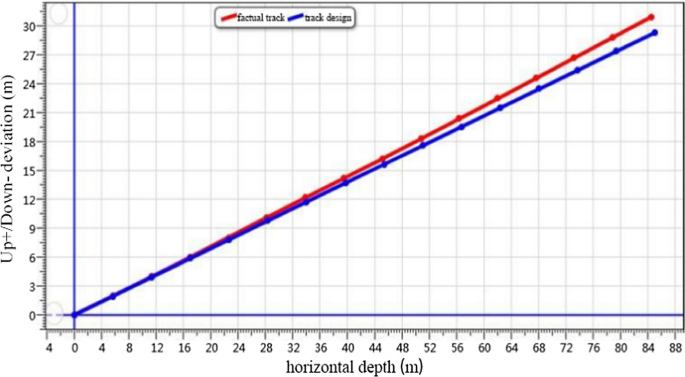
S-36–7-1 Gas drainage borehole trajectory map
-
5.
S-51–3-1 borehole deviation: S-51–3-1 borehole construction 93 m, inclinometer 93 m. The construction dip angle is 15.2°, the downward deviation is 0.43 m, and the downward deviation is 0.27°, as shown in Fig. 15.
Fig. 15 
S-51–3-1 Gas drainage borehole trajectory map
-
6.
According to the above borehole inclinometer data, we get five groups of borehole deviation, as shown in Table 3.


According to the inclinometer data of the five groups of boreholes, we obtain that the average deviation angle of the gas drainage borehole is 0.6°, the minimum deviation angle of the gas drainage borehole is 0.22°, and the maximum deviation angle of the gas drainage borehole is 1.03°. The deviation angle of the gas drainage borehole is basically controlled within a certain range, which can fulfill the requirements of the field construction and has a major significance for the engineering application.
5 Conclusion
By analyzing the deviation mechanism of the drilling rig during the drilling, three main factors are recognized that affect the drilling deviation: Mechanical bending, geometric bending, and other factors. The force mathematical model of drill pipe under different inclination conditions has been studied and the drilling pressure and the drill pipe weight are detected as the main influencing parameters of the drilling deviation, providing a theoretical basis for the controlling drilling deviation parameters.
According to the field situation, a numerical simulation model has been established, which documents that the displacement around the borehole is limited, the borehole area is relatively stable, and the deformation is basically maintained. Based on implications from the stress distribution nephogram and the displacement distribution nephogram we conclude that the larger stress and displacement areas are predominantly area with interlayering soft and hard rock, coal seam areas, and borehole opening position, corresponding to the main areas of borehole deviation.
The drilling trajectory is mainly influenced by geological factors, equipment factors, and human factors. Through the control analysis of the impact of three types of factors on the deviation of the gas drainage borehole, the combination of the drilling control method and the inclination control method is used to monitor the influence of the equipment factors and the human factors in the actual field application. The inclination of the borehole is controlled within a certain range to reduce the deviation of gas drainage borehole.
Data Availability
Enquiries about data availability should be directed to the authors.
References
Cao H (2021) Research on safe and efficient drilling technology of soft outburst coal seam. IOP Conference Series: Earth and Environmental Science, 804(2)
Cheng ZH, Pan H, Zou QL et al (2020) Gas flow characteristics and optimization of gas drainage borehole layout in protective coal seam mining: a case study from the Shaqu Coal Mine, Shanxi Province. China Natural Resources Research 2020:1–13
Fan C, Xu H, Wang G et al (2021a) Determination of roof horizontal long drilling hole layout layer by dynamic porosity evolution law of coal and rock. Powder Technol 394:970–985
Fan ZL, Fan GW, Zhang DS (2021b) Representation of mining permeability and borehole layout optimization for efficient methane drainage. Energy Rep 7:3911–3921
Fu S’A, Lv PY, Wang JJ et al (2017) Characteristics of high level borehole deviation and its influence on extraction effect. J Mining Sci Technol 2(02):158–166
Hawkes CD (2007) Assessing the mechanical stability of horizontal boreholes in coal. Can Geotech J 44(7):797–813
Jeroen VE, Johan F, David S et al (2020) Rock support prediction based on measurement while drilling technology. Bull Eng Geol Env 80:1–17
Kong DZ, Xiong Y, Cheng ZB et al (2021) Stability analysis of coal face based on coal face-support-roof system in steeply inclined coal seam. Geomech Eng 25:233–243
Li YL, She L, Wen LF et al (2020) Sensitivity analysis of drilling parameters in rock rotary drilling process based on orthogonal test method. Eng Geol 270:105576–105576
Liu Z, Yang N, Xiong ZG et al (2021) Modelling and simulation of deflection mechanism in rock drilling processing. J Phys Conf Ser 1948(1).
Liu XT (2020) Research and application of borehole deflection control technology for gas drainage in coal seam. Anhui University of Science and Technology.
Peng QL, Li TH, Liu R et al (2017) Analysis and control of borehole deviation regularity of Longshan Mining area in Hunan. Drilling Eng 44(11):12–15
Shang YQ, Wu GY, Liu QZ et al (2021) The drainage horizon determination of high directional long borehole and gas control effect analysis. Adv Civil Eng 2021:11
Shen Z, Liu ZW, Yi WX et al (2020) Analysis on deviation rule and cause of gas extraction borehole along seam in coal seam. Coal Technol 39(03):103–106
Song XY, Xie ZP (2011) Numerical simulation and inversive study of gas flow field around coal bed borehole. Proc Eng 26(C):1234–1239
Sun XY, Cheng ZH, Chen L et al (2021) Deflection laws of gas drainage boreholes in interbedded soft and hard seams: a case study at Xinzheng Coal Mine, China. Adv Civil Eng.
Tang MY, Wang JH, Zheng PX et al (2019) Numerical analysis and prediction of coal mine methane drainage based on gas-solid coupling model. Technical Gazette 26(3):752–761
Xiong Y, Kong DZ, Cheng ZB et al (2021b) Instability control of roadway Surrounding Rock in close-distance coal seam groups under repeated mining. Energies 14(16):5193
Xiong Y, Kong DZ, Cheng ZB et al (2021a) The comprehensive identification of roof risk in a fully mechanized working face using the cloud model. Mathematics 9(2072)
Xu YP, Wang ML, Liu LN et al (2016) Study on influence radius of gas drainage through borehole based on numerical simulation. Coal Technol 35(02):162–164
Yan XF, Samuel TA, Dong S et al (2018) Horizontal directional drilling: State-of-the-art review of theory and applications. Tunn Undergr Space Technol 72:162–173
Yang T, Zhang J (2020) Gob-side entry retaining technology with advanced empty hole butterfly-shaped weakening in three-soft coal seam in China. Adv Mater Sci Eng 2020:1–17
Yang N (2017) The mechanism of borehole deviation and rectifying method for hydraulic rock drill in medium-deep hole. Suzhou University.
Yao J (2016) Research on numerical simulation and application of curtain grouting. Xihua University.
Yu CX (2020) Research on the Dynamic Characteristics of TBM Airborne Anchor Rod Drill. East China Jiao Tong University.
Yue GW, Liu H, Yue JW et al (2019) Influence radius of gas extraction borehole in an anisotropic coal seam: underground in-situ measurement and modeling. Energy Sci Eng 7(3):694–709
Zhang TJ, Zhang L, Pan HY et al (2015) Stability of gas drainage borehole analysis on rock mechanics parameters with roadway of complex stress. Appl Mech Mater 3753(723):330–335
Zhao HB, Li JY, Liu YH et al (2020) Experimental and measured research on three-dimensional deformation law of gas drainage borehole in coal seam. Int J Min Sci Technol 30(3):397–403
Zheng YH, Zhao ZG, Wu WB et al (2021) Numerical simulation study on measuring coal stress by drilling parameters. Arab J Geosci 14(20)
Acknowledgements
We acknowledge the financial support from the National Natural Science Foundation of China Regional Fund (No. 52064005, 52164005, 52164002), and the funding from Guizhou Science and Technology Plan Project (Qianke Science Support (2021) General 399). We would like to express their gratitude to EditSprings (https://www.editsprings.cn/) for the expert linguistic services provided.
Author information
Authors and Affiliations
Corresponding author
Ethics declarations
Competing Interests
The authors have not disclosed any competing interests.
Additional information
Publisher's Note
Springer Nature remains neutral with regard to jurisdictional claims in published maps and institutional affiliations.
Rights and permissions
About this article

Cite this article
Zhang, Q., Liu, Q., Lou, Y. et al. Deviation Principles of Gas Drainage Drilling in Three-Soft Outburst Coal Seams. Geotech Geol Eng 40, 3147–3168 (2022). https://doi.org/10.1007/s10706-022-02084-y
Received:
Accepted:
Published:
Issue Date:
DOI: https://doi.org/10.1007/s10706-022-02084-y