
Abstract
The high processing efficiency and quality are constant pursuits for modern manufacturing industry. This paper investigated the ablation efficiency and quality of ultrashort pulsed laser ablation of DD6 single crystal alloy based on experiments and theoretical analysis. The experimental results showed that the ablation rate increases with the increase of laser fluence and with the decrease of scanning speed and scanning width, while the ablation efficiency decreases with the increase of laser fluence. A relatively flat and low melted zone ablation surface could be obtained by employing a low laser fluence and high scanning speed. The influence of laser parameters on the ablation diameter, equivalent energy density, and heat accumulation effect was analyzed based on the theory of laser ablation and heat conduction. The theoretical analysis revealed the material removal transforms from plasma or vaporization removal to melt ejection with the pulse energy increases and the scanning speed decreases, which can explain the formation mechanism of surface morphology very well. In addition, the scanning strategy of high efficiency and quality was proposed based on the theoretical analysis and experimental results.
1 Introduction
Nickel-based superalloys are widely used in the fields of aerospace, petrochemical, and marine industries. According to its manufacturing process, the nickel-based superalloy can be divided into three types: wrought superalloy, cast superalloy, and powder metallurgy superalloy. Waspaloy and Inconel are two typical wrought superalloys, owing to its excellent oxidation, corrosion, and high temperature resistance, which are used to manufacture the turbine disk and rotating blade [1, 2] . Monel superalloy is also a typical wrought superalloy, which is used in the field of petrochemical and shipbuilding due to its superior corrosion and wear resistance [3]. In addition, with the development of powder metallurgy technology, the powder metallurgy superalloys have been used in the manufacture of aeroengine turbine disk [4]. However, the casting nickel-based superalloy such as nickel-based single crystal and equiaxed crystal superalloys are still requirement for the turbine blades with higher temperature requirements.
In order to further reduce the surface temperature of turbine blades, the rows of microholes (film cooling holes) are drilled on blade surface to protect the turbine blade from overheating [5]. Compared with electric discharge machining (EDM), electrochemical machining (ECM), and traditional nanosecond laser machining, ultrafast laser machining with pulse duration below 10ps has the potential to become a promising processing method for manufacturing film cooling holes due to the advantages of small heat affected zone and good surface quality. Therefore, effort has also been made by researchers to apply the ultrashort pulsed laser (USP) technology to the film cooling holes drilling on turbine blade [6,7,8]. However, they found the existence of low drilling efficiency and unstable drilling quality during laser drilling, which hence limit the application of ultrashort pulsed laser technology on film cooling holes machining. It is therefore critical to investigate the ultrashort pulsed laser processing of DD6 single crystal superalloy.
However, owing to the complex laser drilling technology, the researchers prefer to perform the metal laser ablation experiments to explore the interaction mechanism between ultrashort pulsed laser and metal material. To solve the problem of low processing efficiency, many studies have been published on the ablation rate (AR) and efficiency of ultrashort pulsed laser ablation of metal material. Yu et al. [9] investigated multiple-pulse drilling of titanium alloy by employing the picosecond laser. They found that the material removal rate linearly increases with the laser fluence. The similar conclusion could be obtained by Zhao et al. [10] in picosecond laser ablation of stainless steel. Wu et al. [11, 12] found besides laser fluence the laser wavelength has also significant effects on ablation rate and efficiency in ultrafast laser ablation of Cr12MoV mold steel. In addition, Ancona et al. [13] demonstrated the femtosecond laser with 800-fs pulse duration could reduce heat accumulate effect and improve processing efficiency comparing with picosecond laser. In addition, effort has been done on the ablation layer depth analysis to improve the laser processing precision [14,15,16].
Besides the ablation efficiency (AE), the ablation topography and microstructure are also affected by the laser parameters. Romoli [14] obtained the processing parameters of lower areal roughness (Sa<100nm) by employing medium laser fluence during laser ablation of AISI316L steel. Sedao et al. [17] found the roughness of ablation surface is relatively low by using the high scanning speed and low repetition rate, while an about 20-μm-thick porous and rugged appear on ablated region by employing a low scanning speed and high repetition rate. Zhao et al. [18] found the ablation morphology can be significantly improved by means of multiple scanning strategy. In addition, Mustafa et al. [19] revealed the ablation regimes transform from hot electron penetration depth to hydrodynamic motion with the increase of laser fluence and pulse number. Villerius et al. [20] found the individual and periodic cone-like protrusions in ultrafast laser ablation of stainless steels by using the low laser fluence (<0.625J/cm2) or high laser fluence (>0.875J/cm2), while the medium laser fluence could process a smooth ablation surface. Bauer et al. [21] found the ablation morphology transforms from dark rough surface covered with small bumps to a smooth surface with the increase of scanning speed, which can be attributed to the aggravation of heat accumulation effect. For this reason, Weber et al. [22, 23] established a three-dimensional heat accumulation model to reveal the potential physical mechanism of different ablation topography during laser ablation process.
In conclusion, an abundant work has been carried out on the metal laser ablation for discussing the ablation mechanism so as to improve the efficiency and quality of ultrashort pulsed laser processing. As far as we know, different materials hold different ablation properties. To solve the problems of low processing efficiency and unstable quality in laser drilling of nickel-based single crystal alloy, the ultrashort pulsed laser ablation experiments on DD6 single crystal superalloy are carried out. And the effects of laser parameters on laser ablation efficiency and surface quality are investigated. The work is expected to obtain optimum processing parameter ranges for nickel-based single crystal alloys and a deeper understanding on the ultrashort pulsed laser ablation mechanism of single crystal alloy.
2 Materials and experimental method
2.1 Materials
The second-generation nickel-based superalloy DD6 is used in this experiment, in which the elementary composition is given in Table 1. The microstructure of the DD6 superalloy consists of cuboidal γ’ precipitates embedded in a γ matrix, as shown in Fig. 1.

The microstructure of the DD6 superalloy
2.2 Experimental device and setup
The ultrashort pulsed laser process system employed in this work is shown in Fig. 2. It is composed of three parts: picosecond laser system (picosecond laser generator, optical transmission system), laser processing system (scanning galvanometer, 3-D mobile platform, and associated blowing device), and control-monitoring system (shutter, computer control system and CCD camera). The picosecond laser generator is originated from Ekspla, Lithuania, which emits a pulsed laser beam with pulse width of 2.1ps and repetition rate of 75 kHz, and the other laser parameters are listed in Table 2. Scanning speed and scanning width are adjusted by the scanning galvanometer, while 3-D mobile platform is used to adjust the relative position of laser beam and specimen. The laser ablation process is assisted by gas blowing of 0.30Mpa and observed in real time with a CCD camera.

Schematic diagram of USP processing device (a) and ablation experimental scheme (b)
The experimental scheme of laser ablation in this work is illustrated in Fig. 2(b), and a detailed scanning strategy is presented in Fig. 3. The rectangular cavities with dimensions of 1.5×1.5mm2 are removed layer by layer; the first layer of the material was ablated along a Z-shaped path and then feeds to the next layer with a 90° rotations. In this work, the influence of laser fluence, scanning speed, and scanning width on ablation rate, ablation efficiency, and quality is investigated, and the experimental parameters that come from engineering experience are given in Table 2 and Fig. 2(b). The scanning speed is from 25 to 200mm/s and scanning width from 0.01 to 0.05mm. The mean laser power is from 5.5 to 30W, which could produce pulsed laser with pulse energy from 72.7 to 400μJ and mean laser fluence from 4.0 to 22.1 J/cm2 at 75-kHz repetition rate and 24-μm focus radius. In this experiment, the focus radius is measured by using the knife-edge method, and laser power is monitored using a power meter. Meanwhile, the scanning layer number Nl (repetition number) is proportional to the scanning speed V to ensure the identical energy deposition per unit area at the same laser fluence, as shown in Fig. 2(b). In addition, before ablation experiments, the specimens for laser ablation experiments are sliced from bar into piece (30*16*1.5mm) by wire electrical discharge machining (WEDM), and then the specimen surface is polished with sandpaper (400–2000#) to ensure the specimen surface roughness below 0.16μm.

Schematic diagram of USP laser ablation in this test
2.3 Experimental procedure
In this paper, the effects of laser processing parameters on ablation rate, efficiency, and ablation quality are studied. The experiments are carried out as follows. Firstly, the ultrashort pulsed laser ablation experiments are conducted according to the experimental scheme of Fig. 2(b) and Fig. 3 (single experiment performed for one group of experimental parameter). And then the specimens are ultrasonic-cleaned in acetone for 15 min. Secondly, the ablated cavity dimensions including length lx, width ly, and depth lz are determined by surface profilometer (InfiniteFocus G4, Austria), and the ablation rate, ablation efficiency, and layer depth are calculated. In this work, the ablation rate (AR) is defined as the ablation volume per unit time or pulse number, which is used to describe material removal rate of ultrashort pulsed laser. While the ablation efficiency (AE) is defined as the ablation volume per unit energy, which is used to characterize the energy utilization ratio of ultrashort pulsed laser ablation. Ablation layer depth dl is defined as the ablation depth per ablation layer, as shown in Fig. 3.
where N is the total pulse number, which can be deduced by N=f·Ttotal, f is the repetition frequency, Ttotal is the total scanning time, Epulse is the single pulse energy, and Nl is the total scanning layer number, as shown in Fig. 2. Thirdly, the surface topography of the ablation zone is measured by scanning electron microscopy (SEM; VEGA 3 LMU, Japan). Finally, specimens are cut along cross section of ablation cavities, then polished, and corroded, and the microstructure of ablation zone is observed by SEM (VEGA 3 LMU, Japan).
3 Experimental results
3.1 Ablation rate and efficiency
The influence of laser parameters on ablation rate is depicted in Fig. 4. It can be seen in Fig. 4 that the ablation rate is increasing linearly with the increase of laser fluence. The ablation rate with large laser fluence of 22.1J/cm2 is about 2–4 times than that with small laser fluence of 4.0J/cm2. Especially for scanning width of 0.01mm, scanning speed of 200mm/s, and laser fluence of 22.1J/cm2, the ablation rate reaches the maximum value of 158.3μm3/pulse as shown in red arrow in Fig. 4a. In addition, the scanning speed also has the significant effect on the ablation rate. The ablation rate of high-speed scanning (purple line) is far greater than that of low-speed scanning (red line) as shown in Fig. 4a and b. While for the large scanning width of 0.05mm (Fig. 4c), the scanning speed has little influence on the ablation rate. Especially for the lower average laser fluence (4–10 J/cm2), the difference of ablation rate at different scanning speed can be negligible. In addition, for the low scanning speed and large laser fluence, the existence of obvious individual cone protruding from ablation surface (will be discussed in Section 4.3), which cause a large measurement error of ablation rate and efficiency. So the data of that is presented in Figs. 4, 5, and 6 as the dashed lines.

Ablation rate of USP laser ablation DD6 single crystal superalloy at different scanning width. a 0.01mm, b 0.03mm, c 0.05mm

Ablation efficiency of USP laser ablation DD6 single crystal superalloy at different scanning width. a 0.01mm, b 0.03mm, c 0.05mm

Ablation layer depth of USP laser ablation DD6 single crystal superalloy
Figure 5 presents the influence of laser parameters on ablation efficiency. It can be seen that the variations of ablation efficiency with laser fluence are contrary to ablation rate in Fig. 4. The ablation efficiency is decreased with the increase of laser fluence, especially for the small scanning width of 0.01 and 0.03mm (Fig. 5a and b). In addition, the ablation efficiency by using high-speed scanning and small scanning width is still higher than that of low scanning speed and large scanning width at the same laser fluence, in which trends are consistent with that of ablation rate in Fig. 4. The result indicated that the scanning strategy of high-speed and small scanning width can obtain better processing efficiency. However, for the large scanning width of 0.05mm, the ablation efficiency is relatively lower, and the difference is relatively little at different scanning speed, as can be seen in Fig. 5c.
3.2 Ablation layer depth
The influence of laser parameters on the ablation layer depth is drawn in Fig. 6. The result shows that the scanning width, laser fluence, and scanning speed all have significant influences on ablation layer depth. The ablation layer depth increases with the increase of laser fluence and the decrease of scanning speed and scanning width. A large ablation layer depth of 25μm/layer can be obtained by a scanning width of 0.01mm, scanning speed of 25mm/s, and laser fluence of 22.1J/cm2. However, the ablation quality is extremely poor by using high laser fluence, low scanning speed, and small scanning width, which will be discussed in Section 3.4 and Section 4.4.
3.3 Surface topography
Figure 7 presents the ablation morphology with different scanning strategies at a constant ablation width of 0.01mm. It can be observed that the ablation topography at different scanning parameters is quite different. When with high scanning speed and low laser fluence, the ablation surface is relatively flat as shown in Fig. 7 D1. However, with the increase of laser fluence or the decrease of scanning speed, the ablation surface deteriorates, and there exists obvious individual cone protruding from the machined surface (Fig. 7 A3, A4, and B4).

Ablation morphology at different scanning strategies, where letter A, 25mm/s, N: 10; B, 50mm/s, N: 20; C, 100mm/s, N: 40; D, 200mm/s, N: 80 and number 1, 4J/cm2; 2, 10 J/cm2; 3, 16 J/cm2; 4, 22J/cm2
In order to investigate in detail the influence of laser parameters on ablation morphology, the ablation cone width is measured (showed in Fig. 7), and the results are presented in Fig. 8. It can be seen in Fig. 8 that the laser parameters have significant influence on the cone size. The cone width of 22.1J/cm2 and 25mm/s is about 360μm, which is over 10 times than that of 4J/cm2 and 200mm/s. In addition, the ablation zone can be divided into four parts by the ablation morphology and cone size as shown in Fig. 7 and Fig. 8: blue zone with low laser fluence and high scanning speed, green zone with medium laser fluence and high scanning speed, orange zone with high laser fluence and low scanning speed, and red zone with maximum laser fluence and lowest scanning speed. For the blue zone with low laser fluence and high scanning speed, the cone shows periodic arrangement with width less than 80μm, as shown in blue zone in Fig. 7. However, with the increase of laser fluence and decrease of scanning speed, the cone width increases linearly and the surface topography transforms from periodic arrangement to individual cone. Especially for the mean laser fluence of 22J/cm2 and scanning speed of 25mm/s, the individual cone protruding from ablation surface (red zone in Fig. 7.) which seriously affects the surface roughness and severe performance of component and should be avoided in processing.

The cone width on ablation surface at different laser parameters
3.4 Microstructure of ablation zone
The microstructure of ablation zone along cross section at four different parameters is measured and the images are shown in Fig. 9. And the parameters are the same for D1, A1, D4, and A4 in Fig. 7, respectively. It can be seen that the cone size increased with the increases of laser fluence and with the decreases of scanning speed, which are consistent with the surface topography. Furthermore, the melted metal is deposited on the top of cones (red dashed line). For low laser fluence and high scanning speed, the melted zone size is smaller than 10μm (Fig. 9a); however, the melted zone size is over 300μm at high laser fluence and low scanning speed (Fig. 9d). Therefore, it can be inferred that the material removal mechanism is quite different for the two parameters.


The SEM images of microstructure by different laser parameters. a 200mm/s, N: 80, 4J/cm2; b 25mm/s, N: 10, 4J/cm2; c 200mm/s, N: 80, 22J/cm2; d 25mm/s, N: 10, 22J/cm2
4 Analyses and discussions
4.1 Ultrashort pulsed laser ablation process
For ultrashort pulsed laser processing, the material removal for pulsed laser processing is originated from single pulse ablation. Therefore, the single pulse ablation process will be discussed first in this section. In this experiment, the energy distribution of the pulsed laser follows the Gaussian distribution, as shown in Fig 10. For Gaussian distribution of the laser beam, the laser fluence F can be characterized as a function of radial position r [25]:

Schematic of correlation between ablation regions and Gaussian distribution of laser fluence
where ω0 is the 1/e2 focus radius of the Gaussian beam. The peak laser fluence Fpk is associated with the corresponding laser pulse energy Epulse by:
where pulse energy Epulse can be calculated by Epulse=P/f. Therefore, the ablation diameter D(=2r), defining as the diameter of the ablation region, becomes a function of the peak laser fluence Fpk:
where Fth is the material ablation threshold. According to Ma et al. [26] , with the increase of laser fluence, the existence of two ablation thresholds (thermal melt and non-thermal melt ablation) during ultrashort pulsed laser ablation of single crystal alloy corresponds to two ablation mechanism: optical absorption and electronic heat conduction. Owing to the most material is removal by heat melt removal in our work, so the thermal melt threshold of single crystal superalloy (5.3J/cm2, measured by Ma et al. [26]) are used in the subsequent calculations. In addition, the laser power used in this experiment is from 5.5 to 30W, which could produce pulsed laser with pulse energy from 72.7 to 400μJ. So the peak laser fluence Fpk and thermal melt diameter D can be calculated by Eqs. (5) and (6), and the results are shown in Table 3. It can be concluded that the peak laser fluence Fpk and ablation diameter D increase with the increase of laser pulse energy. And the thermal melt ablation diameter increases about double from 21.78 to 49.43μm when single pulse energy increases from 72.7 to 400.0μJ.
Owing to the limit of focus diameter, the laser processing is processed in the form of laser scanning in general. Therefore, material removal in laser processing is not only affected by laser pulse energy but also by scanning speed. The influence of scanning speed on laser ablation can be characterized by the effective pulse number Neff and equivalent ablation time Teff. The effective pulse number Neff is defined as the sustained pulse number per focus diameter, which can be deduced by:
The equivalent ablation time is defined as the laser duration per focus diameter, which can be calculated by:
In the work, the scanning speed varies from 25 to 200mm/s. With the repetition rate of 75 kHz and focus radius of 24μm, the equivalent ablation time Teff and effective pulse number Neff can be calculated by Eqs. (7)–(8). And the results are listed in Table 4. It can be found that the effective pulse numbers and the equivalent ablation time are inversely proportional to the scanning speed. The equivalent ablation time increases from 240 to 1920μs when the scanning speed decreased from 200 to 25mm/s.
In addition, the equivalent energy density could be proposed in order to comprehensively consider the influence of laser fluence and scanning speed on laser ablation process. While the equivalent energy density Feff is defined as the laser energy per unit ablation area:
It can be concluded in Eq. (9) that the equivalent energy density is proportional to laser fluence but inversely proportional to scanning speed. For the laser fluence of 22.1 J/cm2 and 25 mm/s, the equivalent energy density Feff calculated by Eq. (9) is 3182.4 J/cm2, which is 44 times than that of 4.0 J/cm2 and 200 mm/s. Therefore, the difference in equivalent energy density under different laser parameter will influence the material removal method, which in turn affects the ablation efficiency and surface topography.
4.2 Analyzation of heat accumulation effect
Owing to ultrashort pulse duration and ultrahigh peak power, the ultrashort pulsed laser can realize “cold cutting” in theory. However, it can be found obvious melted layer obvious melted layer, as shown in Fig. 9, it confirms the existence of heat melt ablation in ultrashort pulse laser ablation of DD6 superalloy. In order to further investigate the ablation mechanism of single crystal alloy, the heat accumulation effect of ultrashort pulsed laser ablation of single crystal alloy is discussed in this work. And the following three-dimensional heat conduction model is used to determine the temperature variation of the ablation zone [23].
In this model, T(t, r) is the temperature variation with time t and position r; ρ is mass density; c is the specific heat capacity; α is the heat diffusion coefficient (α can be calculated by α=λ/ρc); λ is the thermal conductivity; x, y, and z are spatial position coordinates; and r is the distance from the heat source. Qheat is the residual heat of ablation zone, which can be calculated by multiplying pulse energy Epulse by residual heat coefficient ηheat: Qheat =ηheat•Epulse. However, for multiple-pulse ablation, Eq. (10) can be extended and the temperature increase Tsum(t) caused by Np pulses as:
where Tc is the period of pulsed laser, which can be expressed as Tc=1/f and f is the repetition rate. In addition, δ is the Heaviside function. In this model, the mass density of DD6 alloy is 8780kg/m3, and the thermosphysical parameters including thermal conductivity k, specific heat capacity c, and thermal diffusion coefficient α are listed in Table 5. The residual heat coefficient used in this work is 0.398, which is derived from the critical melting condition of DD6 single crystal alloy, as discussed in Appendix. For the laser scanning process, the focus position moves with time and the surface boundary changes from pulse to pulse due to the ablation removal. The two assumptions are made to simplify the calculation process: Firstly, assuming the focus not to move with time and replacing the pulse numbers for multiple-pulse ablation by the equivalent pulses number and secondly, without considering the material removal process from pulse to pulse. Therefore, the calculated temperature of heat accumulation on the central position of the laser beam focus with different pulse number and energy (corresponded to the laser parameters used in this experiment) is presented in Fig. 5.
Figure 11a presents the transient temperature evolution versus time at various pulse energy when pulse number increased from 1 to 18. The horizontal red and blue dashed lines indicate the boiling point (3000°C) and melting point (1350°C), which can be used as approximate temperatures for single crystal alloy. It can be seen in Fig. 11a that for low pulse energy (73μJ), the temperature of the first pulse increases instantaneously and then decreases to about 680°C, which is defined as the heat accumulation temperature after first pulse. Thereafter, the heat accumulation temperature increases gradually with the increasing pulse number and exposure time (red arrow) and reaches 1020°C after the 18 pulses. However, the heat accumulation temperature is still lower than the melting point (1350°C) of the DD6 single crystal alloy. Therefore, it can be inferred that the material is removed by vaporization or plasma. However, for higher pulse energy (400μJ), the heat accumulation temperature reaches 1650°C after the first pulse and then increases to 2700°C after 18 pulses. So it can be inferred that the major material is removed by melting, owing to the heat accumulation temperature that exceeds the melting point and is even close to the boiling point of DD6 superalloy.

Temperature evolution versus ablation time on the center of the laser beam for two different pulse energy and pulse number: a 18 pulse, b 144 pulse
Although the heat accumulation temperature increases slowly with the pulse number increases from 18 to 144, while the ablation duration is increased sharply, which further aggravates the heat accumulation effect, as described in Fig. 11b. Especially for the pulse number of 144 and the pulse energy of 400μJ, the heat accumulation temperature exceeds the boiling point of DD6 single crystal alloy, and the equivalent ablation time increases to 1920μs, which will cause severe melt and ebullition phenomenon on the ablation zone. It can be inferred that the material removal transforms from plasma or vaporization to melt ejection and ebullition with the pulse energy increases and the scanning speed decreases.
4.3 Effect of laser parameter on ablation rate and efficiency
4.3.1 Laser fluence
It can be concluded in Section 3.1 that the ablation rates are increased linearly with the increase of laser fluence, while the ablation efficiencies are decreased with the increase of laser fluence. The increases in ablation rate can be ascribed to the improvement of material removal rate. On the one hand, the pulse energy is increased with the increase of laser fluence, which improves the material ablation depth. On the other hand, the laser ablation diameter increases with the increase of pulse energy, which extends the laser ablation width. Therefore, a high laser fluence not only increases the material ablation depth but also extends the ablation width, both of these can improve material removal volume and finally cause a rapid increase in laser ablation rate. However, the heat accumulation effect aggravation with the increasing of pulse energy, which lead to the large amount of laser energy spreads into the atmosphere and absorbed by the substrate in the meantime and finally causes the reductions of ablation efficiency. However, Račiukaitis et al. [27] proved in the ablation of Al, Ni, and steel that the most efficient material removal takes place when the laser fluence is equal to F≈7.4 Fth. In this work, the laser fluence used only up to 22.1 J/cm2 and has not reached the predicted optimal laser parameter F=7.4*5.3 J/cm2=39.2 J/cm2. Therefore, it can be inferred that the ablation rate will further increase with the increase of laser fluence, while the ablation quality will be further deteriorated owing to the heat accumulation effect according to Section 4.1.
4.3.2 Scanning speed
The ablation rate and efficiency are defined as the ablation volume per pulse number and unit pulse energy in this experiment. Therefore, according to Eq. (2), the ablation rate and efficiency are not affected by scanning speed in theory. However, it has been concluded that the ablation rate and efficiency all increase with the increase of scanning speed. As illustrated in Section 4.1, when the scanning speed decreases from 200 to 25mm/s, the effective pulse number increases from 18 to 144 (corresponding equivalent ablation time increases from 240 to 1920μs), resulting in the rise of heat accumulation temperature. So the large amount of laser energy is spread to substrate material and results in the reduction in laser ablation rate and ablation efficiency. Therefore, it can be concluded that high-speed scanning strategy can achieve higher ablation efficiency.
4.3.3 Scanning width
It can be concluded that the ablation rate and ablation efficiency all decrease with the increase of scanning width. Table 2 shows the thermal ablation diameter increasing from 21.78–49.43μm when the pulse energy increases from 73.7 to 400uJ. However, the scanning width used in this experiment is 10, 30, and 50μm. For small scanning width of 10μm, the laser ablation diameter is larger than the scanning width (the distance between adjacent scanning paths), so the material can be removed effectively. However, for large scanning width of 50μm, the TM ablation diameter is smaller than the scanning width, which causes inadequate material removal and finally leads to low ablation rate. This is also the reason why the ablation rate and efficiency decrease with the increase of scanning width, as depicted in Figs. 4 and 5. Therefore, it can be inferred that the optimal scanning width in this experiment is 0.01mm.
4.4 Effect of laser parameter on ablation topography and microstructure
The ablated cones observed in this experiment are related to many factors including the Gaussian laser beam, scanning path, and laser parameters. For Gaussian laser beam, the laser energy density at the focal center is higher than the border (Fig. 10). Therefore, according to Wang et al. [28], the microgrooves machined by the Gaussian laser beam tend to be U- or V-shaped. So when scanned along one direction, the wave-shaped surface will be ablated as shown in Fig. 12(a) and (b). But the scanning direction of adjacent layers rotates at 90° with each other in this experiment, as described in Fig. 3. So the ablation surface transforms from wave-shaped structure to periodic cones on ablation zone after multiple scanning.

Schematic diagram of formation mechanism of surface microstructure: a Ablation surface, b Enlarged picture of microgroove formation process
However, cone size increases with the decreases of scanning speed and with the increases of laser fluence. This is because the scanning speed and the laser fluence could affect the efficiency energy density and heat accumulation temperature on ablation area. On the one hand, the laser energy density on ablation zone is increased with the increase of laser fluence and with the decrease of scanning speed, leading to ablation groove width and further the cone size increase. On the other hand, the heat accumulation effect increases with the increase of laser fluence and ablation time, and the material removal method transformed from plasma or vaporization to melt ejection. So the large amount of metal and plasma ejected from the groove is deposited on the ablated surface and finally leads to the cone size increase. Especially for high laser fluence and low scanning speed (Fig. 7 A3–A4, B3–B4), the large amount of molten metal is deposited in the ablation surface, which causes large-sized individual cones.
Similar ablation cones are also observed in ablation of other metals. However, the cone size and formation mechanism are quite different. Sedao et al. [17] observed the similar cone during ablation of stainless steel and titanium alloy, but this is not found in Cu and Ni. The reason can be attributed to high electron-phonon coupling coefficient and low thermal conductivity of stainless steel and titanium alloy. The large amount of laser energy is absorbed and cannot be diffused in time, thereby accumulating the large amount of residual heat on the ablated zone, which further eventually causes obvious ablation cones and holes. It can be seen that ablation morphology is not only affected by laser parameters but also by material properties. In this work, the nickel-based alloy holds relatively high electron-phonon coupling coefficient [29], followed by high laser power and relatively long pulse duration. This is the reason for serious heat accumulation effect and the formation of large-sized individual cone under the condition of high laser fluence and low scanning speed.
In addition, the corresponding inference can be verified by microstructure on the ablation zone. For low laser fluence and laser scanning speed, the heat accumulation temperature is relatively low, which causes the most material removed by vaporization or plasma removal, only a little molten metal deposited on the top of the cones and formed the small melted zone. However, with the increase of laser fluence and with the decrease of scanning speed, the equivalent energy density and heat accumulation temperature is high, which lead to the large amount of molten metal ejecting from the ablated zone and hence deposited on the machining surface and formed the large melted zone.
5 Conclusions
This paper investigated ultrashort pulsed laser ablation of nickel-based single crystal superalloy DD6, focusing on the influence of laser parameters on the ablation rate and ablation quality. Meanwhile, the material removal mechanism of ultrashort pulsed laser ablation of DD6 superalloy is discussed in detail. The conclusions can be summarized as follows:
-
(1)
The ablation rates are increased with the increases of laser fluence and with the decreases of scanning speed and scanning width. However, the evolutionary trends of ablation efficiency with laser fluence are opposite to that of ablation rate. Overall, the ablation rate and efficiency at a scanning speed of 200mm/s are 2–3 times than that of 25mm/s.
-
(2)
The quantitative relationships between laser parameters and ablation layer depth are obtained, which could be used for adjusting the feed depth of laser processing and improving the machining precision of ultrashort pulsed laser processing.
-
(3)
A low laser fluence (4–10J/cm2) and high scanning speed (100–200mm/s) could machine a relatively flat surface. On the contrary, the large-sized individual cones and melted metal emerge on ablation zone by employing the large pulse fluence and small scanning speed (>16 J/cm2 and <50mm/s).
-
(4)
The heat accumulation temperature is calculated by three-dimensional heat conduction model. The result reveals the material removal model transforms from plasma or vaporization removal to melt ejection with the pulse energy increases and the scanning speed decreases, which can explain the ablation efficiency and the formation mechanism of ablation morphology.
-
(5)
At the same laser fluence, the scanning strategy of high-speed and multiple scanning can significantly reduce the heat accumulation effect and improve the ablation efficiency and quality of ultrashort pulsed laser processing.
Availability of data and materials
All data generated or analyzed during this study are included in this published article.
References
Hoier P, Surreddi KB, Klement U (2020) Tool wear by dissolution during machining of alloy 718 and Waspaloy: a comparative study using diffusion couples. Int J Adv Manuf Technol 106:1431–1440. https://doi.org/10.1007/s00170-019-04805-9
Rinaldi S, Caruso S, Umbrello D, Filince L, Franchi R, Dekprete A (2018) Machinability of Waspaloy under different cutting and lubri-cooling conditions. Int J Adv Manuf Technol 94:3703–3712. https://doi.org/10.1007/s00170-017-1133-0
Kukliński M, Bartkowska A, Przestacki D (2018) Microstructure and selected properties of Monel 400 alloy after laser heat treatment and laser boriding using diode laser. Int J Adv Manuf Technol 98:3005–3017. https://doi.org/10.1007/s00170-018-2343-9
Li B, Ding W, Yang C, Li C (2019) Grindability of powder metallurgy nickel-base superalloy FGH96 and sensibility analysis of machined surface roughness. Int J Adv Manuf Technol 101:2259–2273. https://doi.org/10.1007/s00170-018-3117-0
Zhang Q, Sun SF, Zhang FY, Wang J, Lv QQ, Shao Y, Liu QY (2020) A study on film hole drilling of IN718 superalloy via laser machining combined with high temperature chemical etching. Int J Adv Manuf Technol 106:155–162. https://doi.org/10.1007/s00170-019-04541-0
Das DK, Pollock TM (2009) Femtosecond laser machining of cooling holes in thermal barrier coated CMSX4 superalloy. J Mater Process Technol 209:5661–5668. https://doi.org/10.1016/j.jmatprotec.2009.05.031
Feng Q, Picard YN, Mcdonald JP, Van Rompay PA, Yalisove SM, Pollock TM (2006) Femtosecond laser machining of single-crystal superalloys through thermal barrier coatings. Mater Sci Eng A 430:203–207. https://doi.org/10.1016/j.msea.2006.05.104
Feng Q, Picard YN, Liu H, Yalisove SM, Mourou G, Pollock TM (2005) Femtosecond laser micromachining of a single-crystal superalloy. Scr Mater 53:511–516. https://doi.org/10.1016/j.scriptamat.2005.05.006
Yu Z, Hu J, Li K (2019) Investigating the multiple-pulse drilling on titanium alloy in picosecond laser. J Mater Process Tech 268:10–17. https://doi.org/10.1016/j.jmatprotec.2018.12.027
Zhao W, Wang W, Jiang G, Li B, Mei X (2015) Ablation and morphological evolution of micro-holes in stainless steel with picosecond laser pulses. Int J Adv Manuf Technol 80:1713–1720. https://doi.org/10.1007/s00170-015-7145-8
Wu B, Liu P, Wang X, Zhang F, Deng L, Duan J (2018) Effect of laser absorption on picosecond laser ablation of Cr12MoV mold steel, 9Cr18 stainless steel and H13A cemented carbide. Opt Laser Technol 101:11–20. https://doi.org/10.1016/j.optlastec.2017.10.036
Wu B, Liu P, Duan J, Deng L, Zeng X, Wang X (2016) Study on picosecond pulse laser ablation of Cr12MoV cold work mold steel. Mater Des 110:549–557. https://doi.org/10.1016/j.matdes.2016.08.006
Ancona A, Döring S, Jauregui C, Röser F, Limpert J, Nolte S (2009) Femtosecond and picosecond laser drilling of metals at high repetition rates and average powers. Opt Lett 34:3304–3306. https://doi.org/10.1364/ol.34.003304
Romoli L (2018) Flattening of surface roughness in ultrashort pulsed laser micro-milling. Precis Eng 51:331–337. https://doi.org/10.1016/j.precisioneng.2017.09.003
Wang X, Ma C, Li C, Kang M, Ehmann K (2018) Influence of pulse energy on machining characteristics in laser induced plasma micro-machining. J Mater Process Tech 262:85–94. https://doi.org/10.1016/j.jmatprotec.2018.06.031
Jia X, Zhao X (2017) Numerical investigation of ultrashort laser interaction with dielectric materials based on a plasma-temperature combined model. J Manuf Process 28:508–514. https://doi.org/10.1016/j.jmapro.2017.04.019
Sedao X, Lenci M, Rudenko A, Faure N, Pascale-Hamri A, Colombier JP (2019) Influence of pulse repetition rate on morphology and material removal rate of ultrafast laser ablated metallic surfaces. Opt Lasers Eng 116:68–74. https://doi.org/10.1016/j.optlaseng.2018.12.009
Zhao W, Wang L, Yu Z, Chen J, Yang J (2019) A processing technology of grooves by picosecond ultrashort pulse laser in Ni alloy: enhancing efficiency and quality. Opt Laser Technol 111:214–221. https://doi.org/10.1016/j.optlastec.2018.09.056
Mustafa H, Matthews DTA, Römer GRBE (2019) Investigation of the ultrashort pulsed laser processing of zinc at 515 nm: morphology, crystallography and ablation threshold. Mater Des:169. https://doi.org/10.1016/j.matdes.2019.107675
Villerius V, Kooiker H, Post J, Pei YT (2019) Ultrashort pulsed laser ablation of stainless steels. Int J Mach Tools Manuf 138:27–35. https://doi.org/10.1016/j.ijmachtools.2018.11.003
Bauer F, Michalowski A, Kiedrowski T, Nolte S (2015) Heat accumulation in ultra-short pulsed scanning laser ablation of metals. Opt Express 23:1035–1043. https://doi.org/10.1364/oe.23.001035
Weber R, Graf T, Freitag C, Feuer A, Kononenko T, Konov VI (2017) Processing constraints resulting from heat accumulation during pulsed and repetitive laser materials processing. Opt Express 25:3966–3979. https://doi.org/10.1364/oe.25.003966
Weber R, Graf T, Berger P, Onuseit V, Wiedenmann M, Freitag C (2014) Heat accumulation during pulsed laser materials processing: erratum. Opt Express 22:28232. https://doi.org/10.1364/oe.22.028232
Zhang Z, Wang W, Jiang R, Zhang X, Xiong Y, Mao Z (2020) Investigation on geometric precision and surface quality of microholes machined by ultrafast laser. Opt Laser Technol:121. https://doi.org/10.1016/j.optlastec.2019.105834
Liang J, Liu W, Li Y, Luo Z, Pang D (2018) A model to predict the ablation width and calculate the ablation threshold of femtosecond laser. Appl Surf Sci 456:482–486. https://doi.org/10.1016/j.apsusc.2018.06.093
Ma S, McDonald JP, Tryon B, Yalisove SM, Pollock TM (2007) Femtosecond laser ablation regimes in a single-crystal superalloy. Metall Mater Trans A 38:2349–2357. https://doi.org/10.1007/s11661-007-9260-0
Račiukaitis G, Brikas M, Gečys P, Voisiat B, Gedvilas M (2009) Use of high repetition rate and high power lasers in microfabrication: how to keep the efficiency high? J Laser Micro Nanoengineering 4:186–191. https://doi.org/10.2961/jlmn.2009.03.0008
Wang W, Mei X, Jiang G, Lei S, Yang C (2008) Effect of two typical focus positions on microstructure shape and morphology in femtosecond laser multi-pulse ablation of metals. Appl Surf Sci 255:2303–2311. https://doi.org/10.1016/j.apsusc.2008.07.100
Wellershoff SS, Hohlfeld J, Güdde J, Matthias E (1999) The role of electron-phonon coupling in femtosecond laser damage of metals. Applied Physics A: Materials Science and Processing 69:99–107. https://doi.org/10.1007/s003390051362
Funding
This study was supported by the NSAF (Grant No. U1830122) and the National Natural Science Foundation of China (Grant No. 51775443). The authors would like to acknowledge the support from the China Scholarship Council (CSC, No. 202006290101).
Author information
Authors and Affiliations
Contributions
Zhanfei Zhang: Conceptualization, methodology, writing—original draft. Wenhu Wang: Conceptualization, methodology, funding acquisition. Chengcheng Jin: Investigation, software, data curation. Ruisong Jiang: Investigation, methodology, writing—original draft. Yifeng Xiong: Conceptualization, methodology. Xiaobing Zhang: Project administration, supervision. Zhong Mao: Methodology, data curation.
Corresponding author
Ethics declarations
Ethics approval
Not applicable.
Consent to participate
We confirm that the manuscript has been read and approved by all named authors.
Consent for publication
This manuscript is approved by all authors for publication. I would like to declare on behalf of my co-authors that the work described was original research and has not been published previously, and not under consideration for publication elsewhere, in whole or in part.
Competing interests
The authors declare no competing interests.
Additional information
Publisher’s note
Springer Nature remains neutral with regard to jurisdictional claims in published maps and institutional affiliations.
Appendix
Appendix
The residual heat coefficient ηheat depends on the material and laser properties, including the pulse energy, pulse duration, and laser energy distribution, according to Weber et al. [23]. In this work, the reverse method is used to calculate the residual heat coefficient ηheat as follows:
-
1)
1) For multiple-pulse ablation process, the temperature increase Tsum(t) resulted from heat accumulation by Nt pulse can be calculated by Eq. (9). So the heat accumulation temperature after Np pulses can be given by:
Therefore, the heat accumulation temperature Tv of after Np pulses is approximately expressed as:
where Tm is the experiment ambient temperature (25°C). And the quantitative relationship of the heat accumulation temperature Tv and residual heat Qheat can be obtained.
-
2)
Then, the line scanning experiments are carried out with the same experiment device. The scanning speed is constant at 100mm/s (corresponding the effective pulse number at 72), and the laser pulse energy is from 72.7–127.3μJ. The ablation morphology shown in Fig. 13 is observed by SEM. It can be seen that the ablation morphology transforms from non-heat melt ablation (Fig. 13a and b) to heat melt ablation (Fig. 13c and d). Especially for the pulse energy of 109.3μJ, the critical melting state is observed on ablation surface (Fig. 13c). Therefore, it could be inferred that the scanning speed of 100mm/s and pulse energy of 109.1μJ is the critical transform condition. In this moment, the heat accumulation temperature reaches the melting point (1350°C) of DD6 superalloy.
Fig. 13. 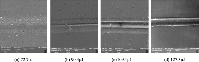
Ablation topography by line scanning with different pulse energy. a 72.7μJ, b 90.4μJ, c 109.1μJ, d 127.3μJ
-
3)
Therefore, the heat accumulation temperature THA (72) that can be determined by Eq. 13 is about 1325°C. Thereafter, the residual heat Qheat and the residual heat coefficient ηheat are 43.5μJ and 0.398 calculated by Eq. 12 and Eq. 8, respectively.

However, the heat accumulation coefficient is affected by many factors as earlier mentioned. In this paper, the approximate of residual heat coefficient is used for subsequent analysis.
Rights and permissions
About this article

Cite this article
Zhang, Z., Wang, W., Jin, C. et al. Investigation on efficiency and quality for ultrashort pulsed laser ablation of nickel-based single crystal alloy DD6. Int J Adv Manuf Technol 114, 883–897 (2021). https://doi.org/10.1007/s00170-021-06883-0
Received:
Accepted:
Published:
Issue Date:
DOI: https://doi.org/10.1007/s00170-021-06883-0